
Related Manuals for Clarke CPSB100


Summary of Contents for Clarke CPSB100
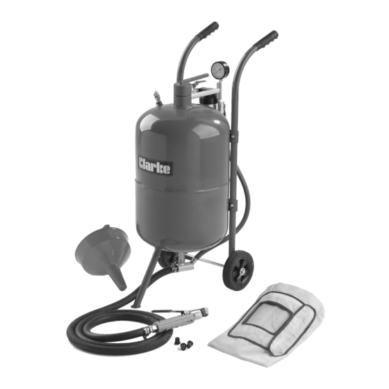
- Page 1 PRESSURISED SANDBLASTER MODEL NO: CPSB100 PART NO: 7640130 OPERATION & MAINTENANCE INSTRUCTIONS ORIGINAL INSTRUCTIONS LS0917 iss 4...
-
Page 2: Introduction
The speed at which certain parts wear depends on the abrasiveness of the materials used. Replacement parts are available from your nearest Clarke International dealer. WHAT IS SUPPLIED •... -
Page 3: Table Of Contents
CONTENTS INTRODUCTION ..............2 GUARANTEE ................2 CONSUMABLES ..............2 WHAT IS SUPPLIED ...............2 CONTENTS ................3 GENERAL SAFETY RULES .............4 ASSEMBLY ................6 FIT HANDLE BARS TO THE TANK ..........6 ASSEMBLE THE FRAME ..............6 ATTACH FRONT LEG ..............7 ATTACH THE HOSE ..............7 OPERATION .................8 SAFETY AND HEALTH CONSIDERATIONS ........8 ABRASIVE SELECTION ...............8 LOADING THE ABRASIVE ............9... -
Page 4: General Safety Rules
GENERAL SAFETY RULES Warning: Compressed air can be dangerous. Ensure that you are thoroughly familiar with all precautions relating to the use of compressors and compressed air supply. 1. Read this instruction manual before connecting the sandblaster to a compressor. 2. - Page 5 15. Always check to make sure that the trigger is not on before connecting blaster to air supply. 16. Store idle tools out of the reach of children and untrained persons. Tools may be dangerous in the hands of untrained users. 17.
-
Page 6: Assembly
ASSEMBLY FIT PRESSURE GAUGE TO THE TANK Screw the pressure gauge onto Fig 1 the sandblaster as shown in Fig 1. FIT HANDLE BARS TO THE TANK Lay the tank on a flat level surface Fig 2 (such as a workbench or table top), with the handlebar mounting brackets facing up, as shown in Fig •... -
Page 7: Assemble The Frame
ASSEMBLE THE FRAME Slide the axle through the axle holes located at the bottom of the handlebars, see Fig 3. 2. Slide a washer onto each end of the axle. Fig 3 Place a wheel onto each end of the axle then slide a washer onto the axle. -
Page 8: Operation
WARNING: THIS SANDBLASTER IS NOT INTENDED FOR USE WITH SILICA BASED ABRASIVES. WHICH HAVE BEEN LINKED TO SEVERE RESPIRATORY DISEASE. ALWAYS USE SILICA SUBSTITUTES (SUCH AS CLARKE GLASS BEAD ABRASIVE. SAFETY AND HEALTH CONSIDERATIONS • Before opening tank make sure that it is not pressurized. Ensure the gauge reads “0”. -
Page 9: Loading The Abrasive
LOADING THE ABRASIVE • To prevent clogging, ensure that the abrasive you use is dry. • While you may re-use abrasive, remember that abrasive grit/ material does wear out. After use, abrasive becomes smoother and rounder, thus reducing its effectiveness. NOTE: Re-using abrasive may also cause clogging due to fine debris contained in the mixture from prior use. -
Page 10: To Start Blasting
TO START BLASTING NOTE: Start with all valves in the closed position. Following the instructions below will help prevent clogging in the delivery hose, outlet manifold and the safety trigger. 1. Connect compressor to the inlet connector. Start compressor and open the air supply valve, see Fig 9. -
Page 11: To Stop Blasting
TO STOP BLASTING While continuing to press and hold Fig 13 the Trigger, turn the abrasive control valve to the closed position, see Fig 13. 2. When you notice only air (no abrasive) is coming out of the safety trigger, you can stop the air flow by releasing the trigger. -
Page 12: Maintenance
MAINTENANCE WARNING: DISCONNECT THE SANDBLASTER FROM THE AIR SUPPLY BEFORE CHANGING ACCESSORIES, ATTEMPTING TO MOVE THE SANDBLASTER OR PERFORM ANY MAINTENANCE. 1. Keep your sandblaster clean, and protect it from damage. 2. When initially pressurising, check for leaks at the top of the tank and at all hoses and fittings. -
Page 13: Replacing The Nozzle
3. Remove the old nozzle (37). 4. lnsert new nozzle. • A pack of 4 Replacement nozzles are available from your Clarke dealer Part number 7640132. 5. Replace the nozzle adapter (38) and firmly screw it onto sandblasting gun. -
Page 14: Specifications
440 x 344 x 850 mm Weight (empty) 19 kg PARTS & SERVICING For Parts & Servicing, please contact your nearest dealer, or CLARKE International, on one of the following numbers. PARTS & SERVICE TEL: 020 8988 7400 PARTS & SERVICE FAX:... -
Page 15: Exploded Diagram & Parts List
EXPLODED DIAGRAM & PARTS LIST... - Page 16 EXPLODED DIAGRAM & PARTS LIST DESCRIPTION PART NO DESCRIPTION PART NO Tank HTCPSB10001 O-Ring HTCPSB10036 Wheels HTCPSB10002 Ceramic Nozzle HTCPSB10037 Cotter Pins HTCPSB10003 Rubber Adapter HTCPSB10038 Front Foot HTCPSB10004 Nozzle Cap Nut HTCPSB10039 Axle HTCPSB10005 Screw ST 4.2 x 16 HTCPSB10040 Handle Bars HTCPSB10006...
-
Page 17: Declaration Of Conformity
DECLARATION OF CONFORMITY... -
Page 18: Notes
NOTES... - Page 19 NOTES...
Need help?
Do you have a question about the CPSB100 and is the answer not in the manual?
Questions and answers