Advertisement
Quick Links
Advertisement

Related Manuals for Speco CVC5715DNVW


Summary of Contents for Speco CVC5715DNVW
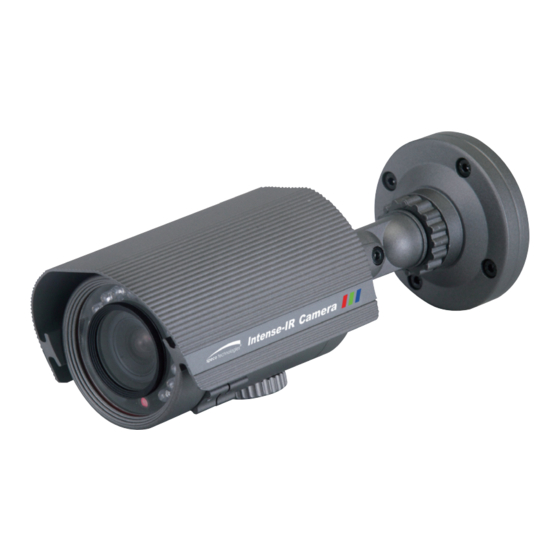
- Page 1 INSTRUCTION MANUAL Intense-IR Camera CVC5715DNV CVC5715DNVW...
- Page 2 Contents ............1 ◑ Precautions ..........2, 3 ◑ Safety Instructions ........4 ◑ Package Contents ........5 ◑ Camera Installation ........6-8 ◑ ..........9 ◑ Camera Dimension ........10 ◑ OSD Menu Details ........11- 35 ◑ Trouble Shooting ......... 36 ◑...
- Page 3 Only use the camera under conditions Severe lighting change or flicker can This is one of the most important parts of the where temperatures are between cause the camera to work improperly. camera. Be careful not to leave -10°C and +50°C. Be especially careful to provide fingerprints on the lens cover.
- Page 4 CAUTION RISK OF ELECTRIC SHOCK CAUTION DO NOT OPEN CAUTION RISK OF ELECTRIC SHOCK CAUTION:TO REDUCE THE RISK OF ELECTRIC SHOCK RISK OF ELECTRIC SHOCK DO NOT OPEN DO NOT OPEN DO NOT REMOVE COVER(OR BACK). CAUTION:TO REDUCE THE RISK OF ELECTRIC SHOCK NO USER-SERVICEABLE PARTS INSIDE.
- Page 5 ◑ ◑ There are no user serviceable parts inside ◑ Do not disassemble this camera other than to make initial adjustments ◑ Use a UL approved regulated 24 volt AC or 12 volt DC power supply rical shock ◑ ◑ Please insure that your installation area can support the weight of the camera ◑...
- Page 6 Package Contents Please make sure that the following items are included in the Package: 1) CVC5715DNV, CVC5715DNVW • 1 Video Test Connector, Power Jack • 1 2Axis Bracket Adaptor • 2 Wrenches • Set Screw - 4 Tapping Screws 4x20...
-
Page 8: Camera Installation
CAMERA INSTALLATION Compatibility 1) CVC5715DNV, CVC5715DNVW INTCM... - Page 9 CAMERA INSTALLATION 1. CVC5715DNV, CVC5715DNVW WALL CAMER A ASSEMBLY 2AXIS BRACKET ADAPTOR TAPPING SCREW 4X20, 4EA HEXAGON SOCKET SCREW M4X7, 4EA...
- Page 10 (4mm-9mm) True Day/Night Capability ICR-IR Cut Filter Removable 850nm IR LEDs * 14pcs IR LED's 14EA & Heater's 2EA SPECIFICATIONS CVC5715DNV / CVC5715DNVW MODEL Sensor 1/3" SONY Super HAD ll CCD Total Pixels NTSC=811(H) * 508(V) / PAL=795(H) * 595(V)
- Page 11 CAMERA INSTALLATION 1) CVC5715DNV, CVC5715DNVW 7.63” 2.87” 4.64” 7.48”...
-
Page 12: Osd Control Button
OSD Control Button 1. Type A, Type B, Type C of OSD button could be used when it needs to OSD control. 2. Type D is extra Option (wired Remote controller) -
Page 13: How To Set Up The Camera Menu
How to Set Up the camera menu Setup Menu ●... -
Page 16: Menu Setup
Menu Set Up Menu items can be selected by using the OSD buttons of the camera 1. Press the Set Up button. * The Set Up menu will be displayed on the monitor. SETUP 1.LENS 2.EXPOSURE 3.WHITE BAL 4.DAY / NIGHT COLOR 5.3DNR 6.SPECIAL... - Page 17 3. Change menu settings using the Left or Right button. * Available values or Status are displayed by pressing the Left or Right buttons. Press the button until desired value / status is displayed. 4. After Changing the setting move the arrow indicator to EXIT and press the SET button to EXIT.
- Page 18 NOTE * When DC is selected, the brightness can be adjusted. The brightness control range is 1 ~ 100. Lens BRIGHTNESS RETURN 3. Press the RETURN to return to the SETUP menu. Exposure This function is used to select Automatic or Manual shutter speed control. 1.
- Page 19 EXPOSURE SHUTTER AUTO MIDDLE SENS-UP AUTO D-WDR RETURN NOTE *Shutter: Select Shutter using the Up or Down button, you can adjust the shutter speed from 1/60, FLK, 1/250~1/100,000. →FLK: Select FLK mode if flickering occurs; caused by the unmatched frequency of electric light.
-
Page 20: Back Light(Blc)
* RETURN: Select Return to save the changes in the EXPOSURE menu and retun to the SETUP menu. NOTE * Pressing the SET button in AUTO mode allows adjustment of image brightness by increasing or decreasing the shutter speed (x2 ~x256). * The higher the level, the brighter the image becomes, but it is possible that an after image (ghosting) could appear. - Page 21 POSITION SIZE PICTURE 1 PICTURE 2 * HSBLE: HSBLC function is especially effective for reading car number plates at the night time. You can select and define the required observation area for the target object and ignore a strong light area. Press the "ENTER"...
- Page 22 HSBLC OFF HSBLC ON * D-WDR: This camera which is using 3D-DNR DSP provides intelligent light level control to overcome even strong backlight conditions. →OFF: D-WDR function does not operate. When there are simultaneous bright & dark image area WDR makes them both distinct and can be selected as OUTDOOR and INDOOR.
-
Page 23: White Balance
White Balance The White Balance function is used to control the “on-screen” colors. 1. Move the arrow indicator to WHITE BAL on the SETUP menu screen using the Up and Down button. 2. Select the desired mode by using the Left or Right button. SETUP 1.LENS 2.EXPOSURE... - Page 24 Day / Night Picture can be displayed in either colour of black and white. 1. Select DAY / NIGHT using the Up or Down button on the SETUP menu screen. SETUP 1.LENS 2.EXPOSURE 3.WHITE BAL 4.DAY / NIGHT AUTO 5.3DNR 6.SPECIAL 7.ADJUST 8.RESET...
- Page 25 IR SMART GAIN SIZE AREA RETURN AREA SMART IR OFF SMART IR ON → AUTO: The mode will automatically switches to COLOR in normal condition and switches to BW mode when ambient illumination is low. Press the SET button to set the switching time or D→N(AGC), N→D(AGC) in AUTO mode. DAY &...
- Page 26 3DNR 3DNR is used to reduce the level of background noise in a low luminance environment. 1. Move the arrow indicator to 3DNR by using the Up and Down button. SETUP 1.LENS 2.EXPOSURE 3.WHITE BAL 4.DAY / NIGHT AUTO 5.3DNR 6.SPECIAL 7.ADJUST 8.RESET...
- Page 27 Special When the SETUP menu screen is displayed, select SPECIAL using the Up and Down buttons. SETUP 1.LENS 2.EXPOSURE 3.WHITE BAL 4.DAY / NIGHT AUTO 5.3DNR 6.SPECIAL 7.ADJUST 8.RESET 9.EXIT Select one of the mode using the Up and Down button. SPECIAL 1.
-
Page 28: Camera Title
NOTE * When CAMERA TITLE is set to OFF, the CAMERA TITLE is not displayed on the monitor. 1-3) Press the SETUP button. CAMERA TITLE 0 1 2 3 4 5 6 7 8 9 A B C D E F G H I J K L M N O P Q R S T U V W X Y Z ▷... - Page 29 NOTE * In cases where the wrong Camera ID has been input..Move the cursor to CLR and press SETUP button to erase characters from left to right, and repeat the above steps to input the characters again. 1-5) To select the position where the Camera ID should be displayed on the screen. ①...
- Page 30 ③ Select a new position by using the four C A M 1 directional button, Press the SET button to confirm the position. 2. D - EFFECT Move the cursor to D-EFFECT and press the SET button to set the other image functions. D-EFFECT FREEZE MIRROR...
- Page 31 * V-FLIP : Flip the image vertically on the screen. * ROTATE : Flip the horizontal image vertically on the screen. * OFF : Disabled. MIRROR ON MIRROR OFF 2-2) D - ZOOM: Digital zoom available, range x1 ~ x32. PAN : The pan range can be controlled between -10 ~ + 100 TILT : The tilt range can be controlled between -10 ~ + 100 D-ZOOM...
- Page 32 2-3) GAMMA : Desired gamma values can be adjusted between 0.05 ~ 1.00. 2-4) NEG. IMAGE : ON : Activates negative image just like film OFF : Normal image 2-5) RETURN : Move the arrow indicator to RETURN after complete the setup to return to SPECIAL menu. 3.
- Page 33 4. PRIVACY Hide an area you want to hide on the screen. 4-1). When the SPECIAL menu screen is displayed, press the Up and Down buttons to set to PRIVACY. PRIVACY AREA SELECT AREA1 AREA DISPLAY COLOR RETURN POSITION SIZE 4-2).
- Page 34 ③ Move the arrow indicator to WIDTH to make desired width of cells to increase or decrease by using the Left / Right button between the level 0 ~ 100. ④ Move the arrow indicator to HEIGHT to make desired height of cells to increase or decrease by using the Left / Right button between the level 0 ~ 100.
- Page 35 ADJUST 1. When the SETUP menu screen is displayed, select ADJUST using the Up and Down buttons. SETUP 1.LENS 2.EXPOSURE 3.WHITE BAL 4.DAY / NIGHT AUTO 5.3DNR 6.SPECIAL 7.ADJUST 8.RESET 9.EXIT 2. Select the desired mode by using Up or Down button. ADJUST SHARPNESS MONITOR...
- Page 36 RESET Resets the camera settings to the factory defaults. SETUP RESET 1.LENS FACTORY 2.EXPOSURE RETURN 3.WHITE BAL 4.DAY / NIGHT AUTO 5.3DNR 6.SPECIAL 7.ADJUST 8.RESET 9.EXIT EXIT Press the SET button in the EXIT menu to save the current settings and exit the SETUP menu. SETUP 1.LENS 2.EXPOSURE...
-
Page 37: Troubleshooting
Trouble Shooting PROBLEM POSSIBLE CAUSE ☞ Check the power cable, power supply output and video Northing appears on connection between the camera and monitor. the screen. ☞ Are the camera lens or the lens glass dirty? Clean the lens / glass with a soft clean cloth. The image on the ☞... - Page 39 - MEMO -...
- Page 40 - MEMO -...
- Page 41 200 New Highway Amityville, NY 11701 631-957-8700 1 800 645 5516 www.specotech.com...
Need help?
Do you have a question about the CVC5715DNVW and is the answer not in the manual?
Questions and answers