Table of Contents
Advertisement
Quick Links
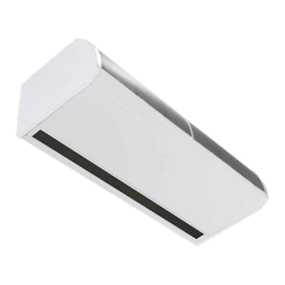
AMBIENT, LPHW AND ELECTRIC HEATED
GUARDIAN GB, GR AND GS
COMMERCIAL AIR CURTAIN RANGE
INSTALLATION MANUAL
BS EN ISO 12100:2010 Safety of machinery.
BS EN 60204-1:2018 Safety of machinery. Electrical equipment of machines.
BS EN 55014-1:2017 Electromagnetic compatibility.
BS EN 60335-2-30:2009+A11:2012 Safety. Requirements for room heaters to the following
European CE directives- 2006/95/EC - low voltage; 2014/30/EU - electromagnetic compatibility
Please read this document carefully before commencing installation, commissioning and/or servicing.
Leave it with the end user/site agent to be placed in their premises technical file after installation.
WARNING
Improper installation, adjustment, alteration, service or maintenance can cause property damage, injury or death.
All work must be carried out by appropriately qualified persons.
The manufacturer does not take any responsibility in the event of non-observance of the regulations concerning the connection of the apparatus causing a
dangerous operation possibly resulting in damage to the apparatus and/or environment in which the unit is installed.
MANUAL PART NO. D301214 ISS D
Advertisement
Table of Contents

Related Manuals for Reznor GUARDIAN GB


Summary of Contents for Reznor GUARDIAN GB
- Page 1 AMBIENT, LPHW AND ELECTRIC HEATED GUARDIAN GB, GR AND GS COMMERCIAL AIR CURTAIN RANGE INSTALLATION MANUAL BS EN ISO 12100:2010 Safety of machinery. BS EN 60204-1:2018 Safety of machinery. Electrical equipment of machines. BS EN 55014-1:2017 Electromagnetic compatibility. BS EN 60335-2-30:2009+A11:2012 Safety. Requirements for room heaters to the following European CE directives- 2006/95/EC - low voltage;...
-
Page 2: Table Of Contents
Contents User operation ..........25 General Information (G) 1. Set operating mode .........25 Guardian air curtain range .........4 2. All off mode ..........25 3. All auto mode .........25 General product information .......4 4. All on mode ..........25 Health and safety ..........4 5. - Page 3 Spare Parts (SP) Spare parts............39 General .............39 Parts Replacement (PR) Parts replacement..........40 Control panel ..........40 Heating element ..........40 Fan deck ............40...
-
Page 4: Guardian Air Curtain Range
/ program panel and 10m length of RJ45 communication cable. The panel allows the user to control either a single air curtain, or a network of up to 16 air curtains. Page No 4 Reznor, Guardian GB GR and GS, Installation Manual, EN 2021-08, D301214 Iss D... -
Page 5: Requirements
Additionally with LPHW heated air curtains, check that the flow / return temperature and pressure of the LPHW system are compatible. Reznor, Guardian GB GR and GS, Installation Manual, EN 2021-08, D301214 Iss D Page No 5... -
Page 6: Technical Data (Td) Technical Data
(No Jumpers 9/12/18kW) °C °C Temperature rise - High °C (Jumpers in 12/18/24kW) °C Weight L, M, H 34.5 64.5 External fuse size (D type MCB) Page No 6 Reznor, Guardian GB GR and GS, Installation Manual, EN 2021-08, D301214 Iss D... -
Page 7: Fuses
Signal Pro board has two additional large fuses to protect the heating elements (F2 and F3). Figure 1 Fuse location electric model board shown Reznor, Guardian GB GR and GS, Installation Manual, EN 2021-08, D301214 Iss D Page No 7... -
Page 8: Lphw Models Water Coil Technical Information
Fluid Pressure Drop 90.86 103.3 73.33 47.12 25.31 Manifold Pressure Drop 5.46 6.27 4.17 2.48 1.21 Total Pressure Drop Fluid Side 96.32 109.57 77.5 49.6 26.52 Page No 8 Reznor, Guardian GB GR and GS, Installation Manual, EN 2021-08, D301214 Iss D... -
Page 9: Dimensions. Gs Surface Mounted Models
The minimum mounting height (floor to grille outlet) is 1.8m. The recommended maximum mounting height is 3m for standard fan setting & 4m for high Reznor, Guardian GB GR and GS, Installation Manual, EN 2021-08, D301214 Iss D Page No 9... -
Page 10: Dimensions. Gr Recess Mounted Models
The minimum mounting height (floor to grille outlet) is 1.8m. The recommended maximum mounting height is 3m for standard fan setting & 4m for high. Page No 10 Reznor, Guardian GB GR and GS, Installation Manual, EN 2021-08, D301214 Iss D... -
Page 11: Dimensions. Gb Bulkhead Mounted Models
The minimum mounting height (floor to grille outlet) is 1.8m. The recommended maximum mounting height is 3m for standard fan setting & 4m for high. Reznor, Guardian GB GR and GS, Installation Manual, EN 2021-08, D301214 Iss D Page No 11... -
Page 12: Signal Pro Display Panel Dimensions
Figure 5.2 Figure 5.1 Flush mounting plastic conduit box Figure 5 Surface mount box (by others) Figure 5.2 Surface mounting back box dimensions Page No 12 Reznor, Guardian GB GR and GS, Installation Manual, EN 2021-08, D301214 Iss D... -
Page 13: Component Layout
Control panel Installer terminal block Fan motor Fan deck Resistor (1500 only) Heating element Table 5 GS & GR components Figure 7 Component layout GR Reznor, Guardian GB GR and GS, Installation Manual, EN 2021-08, D301214 Iss D Page No 13... -
Page 14: Installation
Figure 8 Honeycomb outlet position near to the door adjustable angle of 0 to -5° Page No 14 Reznor, Guardian GB GR and GS, Installation Manual, EN 2021-08, D301214 Iss D... -
Page 15: Installation Process
(see figure 13). Figure 9.1 GS cover fixing point Figure 12 GR cover fixing point Figure 9.2 GS cover fixing point Figure 13 GR bolt hinge Reznor, Guardian GB GR and GS, Installation Manual, EN 2021-08, D301214 Iss D Page No 15... -
Page 16: Suspending On Threaded Rods
Please ensure that adequate fixings and wall structure are present to support the unit weight. Page No 16 Reznor, Guardian GB GR and GS, Installation Manual, EN 2021-08, D301214 Iss D... -
Page 17: Installation Details - Lphw Only
4. Follow the instructions 6 to 10 of the drop rod mounting instructions grille LPHW Connection Figure 17 Typical schematic of a 3-port valve system. Figure 16 Mounting bracket option Reznor, Guardian GB GR and GS, Installation Manual, EN 2021-08, D301214 Iss D Page No 17... -
Page 18: Signal Pro Display Panel
‘TIMER’. (Contacts closed to enable). Only air curtain(s) wired this way will respond to the enable signal. Page No 18 Reznor, Guardian GB GR and GS, Installation Manual, EN 2021-08, D301214 Iss D... -
Page 19: Standard And High Capacity Fan & Heat Settings
Figure 19.1 Heat capacity jumpers HIGH capacity (jumpers fitted) Figure 19.2 Heat capacity jumper pack part number 1026901 Reznor, Guardian GB GR and GS, Installation Manual, EN 2021-08, D301214 Iss D Page No 19... -
Page 20: Wiring Diagrams
5 & 6 Optional door contact 1 & 2 Not used PCB Fuses Rating (A) T1H (slow blow) Table 6 Cable specification ambient Page No 20 Reznor, Guardian GB GR and GS, Installation Manual, EN 2021-08, D301214 Iss D... -
Page 21: Installer Wiring Electric Heated Three Phase Only
An external circuit breaker with the appropriate rating should be installed for the protection of the installation Reznor, Guardian GB GR and GS, Installation Manual, EN 2021-08, D301214 Iss D Page No 21... -
Page 22: Installer Wiring Lphw Single Phase
External circuit breaker with the appropriate T1H (slow blow) rating should be installed for the protection of the Table 8.1 Cable specification LPHW heated installation. Page No 22 Reznor, Guardian GB GR and GS, Installation Manual, EN 2021-08, D301214 Iss D... -
Page 23: Introduction
The RJ45 cable is 10m as standard however it is Figure 24 Air curtain address numbers available in 2m, 20m, 30m, 50m and 100m lengths. Reznor, Guardian GB GR and GS, Installation Manual, EN 2021-08, D301214 Iss D Page No 23... -
Page 24: Keypad Buttons
ON1 - ‘ON’ denotes this air curtain is active, ‘1’ “INTERLOCK TIMER”, “INTERLOCK FILTER” or denotes Internal Timer “INTERLOCK STAT” will show in the bottom line. OS:23° - denotes Outside temperature 23°C Page No 24 Reznor, Guardian GB GR and GS, Installation Manual, EN 2021-08, D301214 Iss D... -
Page 25: User Operation
If address was individual then next address is flashing. Use PLUS and MINUS to set address, OK to 2. All Off mode. modify temperature or MENU to exit. Reznor, Guardian GB GR and GS, Installation Manual, EN 2021-08, D301214 Iss D Page No 25... -
Page 26: Set Heat On/Off
When the user reaches the end of the menu they have a choice: Use PLUS and MINUS to adjust hours (00 to 23) then Minutes starts flashing. Page No 26 Reznor, Guardian GB GR and GS, Installation Manual, EN 2021-08, D301214 Iss D... -
Page 27: Engineers Instructions
Fan speed starts flashing. Use PLUS and MINUS to OK starts outside temperature limit flashing. select off, 1, 2, 3 then OK to set. Reznor, Guardian GB GR and GS, Installation Manual, EN 2021-08, D301214 Iss D Page No 27... -
Page 28: Set Temperature Limits
Use PLUS and MINUS to select low temperature limit or on then OK. between 5 and current high temperature limit, then Door input interlock is flashing. Page No 28 Reznor, Guardian GB GR and GS, Installation Manual, EN 2021-08, D301214 Iss D... -
Page 29: Display Hours Run
Use PLUS and MINUS to select language from available options then OK and back to engineers menu. OK returns to home screen and MENU restarts engineers menu. Reznor, Guardian GB GR and GS, Installation Manual, EN 2021-08, D301214 Iss D Page No 29... -
Page 30: Diagnostics
“- -“ if temperature range error or “ “ if no sensor. T**, electric control temperature, 0 to 99 or “- -“ if temperature range error. Page No 30 Reznor, Guardian GB GR and GS, Installation Manual, EN 2021-08, D301214 Iss D... -
Page 31: Electric Air Outlet Temperature When "Outside Limit" Is Set
In this example the outside limit temperature has been set to 22°C, the outlet air temperature (eg Door Open or Door Closed temperature) has been set to 25°C and the elevate at zero temperature has been set to 5°C. Reznor, Guardian GB GR and GS, Installation Manual, EN 2021-08, D301214 Iss D Page No 31... -
Page 32: Lphw Flow And Return Temperature When "Outside Limit" Is Set
In this example the outside limit temperature has been set to 22°C, the full flow/return at temperature has been set to 12°C and the characteristic flow and return temperature has been set to 82/71°C. Page No 32 Reznor, Guardian GB GR and GS, Installation Manual, EN 2021-08, D301214 Iss D... -
Page 33: Modbus Protocol
Write single coil Coils 13 to 24 Write single register Registers 125, 126 All other MODBUS function codes will generate exception code 01, function not recognised. Reznor, Guardian GB GR and GS, Installation Manual, EN 2021-08, D301214 Iss D Page No 33... -
Page 34: Function Arguments Coils
System reset (*) (*) A read or write to this coil causes the addressed controller to execute a restart as if being powered Page No 34 Reznor, Guardian GB GR and GS, Installation Manual, EN 2021-08, D301214 Iss D... -
Page 35: Maintenance And Servicing
3. With a soft brush clean away any dust from the motor and elements. 4. Check the security of all the components 5. Check for any signs of deterioration and replace components as necessary Reznor, Guardian GB GR and GS, Installation Manual, EN 2021-08, D301214 Iss D Page No 35... -
Page 36: Inlet Foam Filter Replacement Gr
1metre back over the honeycomb to secure 1.5 metre 2 metre Table 9 Temperature sensor position Page No 36 Reznor, Guardian GB GR and GS, Installation Manual, EN 2021-08, D301214 Iss D... -
Page 37: Fault Finding
Figure 31 Thermal cut-out Display panel. Any fault will be described on the display panel. until the fault has been cleared. Reznor, Guardian GB GR and GS, Installation Manual, EN 2021-08, D301214 Iss D Page No 37... -
Page 38: Signal Pro Fault Codes
Replace faulty sensor control Overheat stat open Overheat stat open Replace overheat Fan operating, no heat circuit circuit thermostat Table 10 Signal Pro faults and remedies Page No 38 Reznor, Guardian GB GR and GS, Installation Manual, EN 2021-08, D301214 Iss D... - Page 39 Jumper pack (high and low capacity) 1026901 Heating element fuse 900471 LPHW Models Control panel (base unit) LPHWBU45-1 LPHW coil 1026692 1026693 1026694 Table 11 Spare parts Reznor, Guardian GB GR and GS, Installation Manual, EN 2021-08, D301214 Iss D Page No 39...
- Page 40 4. Disconnect the wires at the heating element to the control panel 5. Remove the fixing bolts in the fan deck mounting plate which secures the heating element. 6. Remove the heating element Page No 40 Reznor, Guardian GB GR and GS, Installation Manual, EN 2021-08, D301214 Iss D...
- Page 41 Notes...
- Page 42 Notes...
- Page 43 Notes...
- Page 44 Tel +44 (0)1384 489250 Fax +44 (0)1384 489707 reznorsales@nortek.com www.reznor.eu Nortek Global HVAC is a registered trademark of the Nortek Global HVAC limited. Because of the continuous product innovation, Nortek Global HVAC reserves the right to change product specification without due notice.
Need help?
Do you have a question about the GUARDIAN GB and is the answer not in the manual?
Questions and answers