Table of Contents
Advertisement
Quick Links
GAS-FIRED LOW-INTENSITY RADIANT TUBE HEATER
INSTALLATION, OPERATION, AND MAINTENANCE
• Failure to follow safety warnings exactly could result in serious injury, death, or property
damage.
• Improper installation, adjustment, alteration, service, or maintenance can cause serious injury,
death, or property damage.
• Installation and service must be performed by a qualified installer, service agency, or the
gas supplier.
• Be sure to read and understand the installation, operation, and service instructions in this
manual.
• Do not store or use gasoline or other flammable vapors and liquids in the vicinity of this or
any other appliance.
• Do not try to light any appliance.
• Do not touch any electrical switch; do not use any phone in your building.
• Leave the building immediately.
• Immediately call your gas supplier from a phone remote from the building. Follow the gas
supplier's instructions.
• If you cannot reach your gas supplier, call the fire department.
DO NOT DESTROY. PLEASE READ CAREFULLY. KEEP IN A SAFE PLACE FOR FUTURE REFERENCE.
Revision: VZ-VZH-VZT-IOM (08-24) 1047121-A
MODELS VZ, VZH, AND VZT
⚠ DANGER ⚠
FIRE OR EXPLOSION HAZARD
WHAT TO DO IF YOU SMELL GAS
Supersedes: VZ-VZH-IOM (06-24) 1047121-0
Advertisement
Table of Contents

Related Manuals for Reznor VZ


Summary of Contents for Reznor VZ
- Page 1 Supersedes: VZ-VZH-IOM (06-24) 1047121-0 GAS-FIRED LOW-INTENSITY RADIANT TUBE HEATER INSTALLATION, OPERATION, AND MAINTENANCE MODELS VZ, VZH, AND VZT ⚠ DANGER ⚠ FIRE OR EXPLOSION HAZARD • Failure to follow safety warnings exactly could result in serious injury, death, or property damage.
-
Page 2: Table Of Contents
Shutdown . . . . . . . . . . . . . . . . . . . . . . . . . . . . . . . . . . . . . . . . . . . . . . . . . . . . . . . . . . . . . . . . . . . . . . . . . . . . . . 42 VZ-VZH-VZT-IOM (08-24) 1047121-A... -
Page 3: General Information
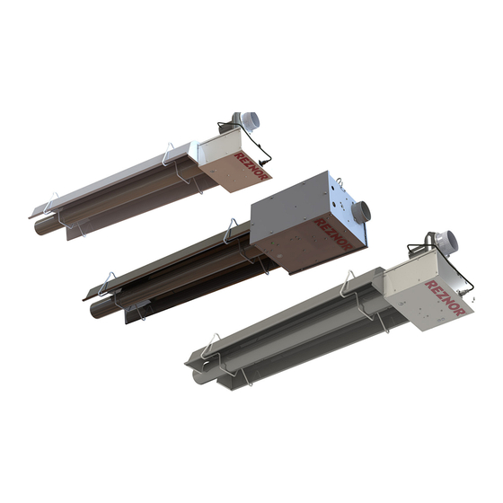
• This manual applies only to the models listed . Accessories referenced may not apply to all models . Model Features • Model VZ (single-stage burner) and model VZT (two-stage (low- and high-fire) burner): features painted burner cabinet with external blower and motor assembly—designed for non-harsh environment indoor installations . -
Page 4: Warranty
Repair Garages (ANSI/NFPA No . 88B, latest edition) . In Canada, installations in aircraft hangars public garages should be in accordance the CSA B149 code . • If the heater is being installed in the Commonwealth of Massachusetts, installation must be performed by a licensed plumber or licensed gas fitter . VZ-VZH-VZT-IOM (08-24) 1047121-A... -
Page 5: Dimensions
BLOWER MOTOR PLUG RECEPTACLE TOP VIEW REAR VIEW CONNECTION 13-15/64 (337) 6-1/32 (154) 3 (77) 2-1/64 (52) 3-1/16 2 (51) (78) 10-3/4 12-1/2 (274) (318) LEFT SIDE VIEW FRONT VIEW Figure 1. Model VZ Burner Cabinet Dimensions VZ-VZH-VZT-IOM (08-24) 1047121-A... -
Page 6: Bottom View
(79) SUPPLY WIRING ENTRANCE 3-1/2 (89) 17-1/2 (445) 4-23/64 (111) GAS CONNECTION 4-29/32 (125) REAR VIEW TOP VIEW 9-1/2 (242) 4-3/4 (121) 6-3/4 (172) 13-15/32 (172) FRONT VIEW BOTTOM VIEW Figure 2. Model VZH Burner Cabinet Dimensions VZ-VZH-VZT-IOM (08-24) 1047121-A... -
Page 7: Left Side View
BLOWER MOTOR PLUG RECEPTACLE BOTTOM VIEW REAR VIEW CONNECTION 13-15/64 (337) 6-1/32 (154) 3 (77) 2-1/64 (52) 3-1/16 2 (51) (78) 12-1/2 10-3/4 (318) (274) LEFT SIDE VIEW FRONT VIEW Figure 3. Model VZT Burner Cabinet Dimensions VZ-VZH-VZT-IOM (08-24) 1047121-A... -
Page 8: Heater Location
40°F (4°C). Operating under low ambient conditions may cause condensation to form in the heat exchanger. • Do not locate a model VZ or VZT heater where it may be exposed to water spray, rain, or dripping water. - Page 9 Clearances listed apply to when the protective shield is installed on the first 10 feet (3 meters) of tube extending from the burner cabinet . The bottom clearances from that point are the same as those for a straight tube with a level reflector (configuration A) . The protective shield is not available for unit sizes 175 and 200 . VZ-VZH-VZT-IOM (08-24) 1047121-A...
- Page 10 GENERAL INFORMATION—CONTINUED Heater Location—Continued Clearances—Continued Figure 4. Tube and Reflector Configuration VZ-VZH-VZT-IOM (08-24) 1047121-A...
-
Page 11: Halogenated Hydrocarbons
U-tube with aluminum reflectors 19 (8 .7) U-tube with SST reflectors 20 (9 .1) L-tube 6 (2 .8) Model VZ burner cabinet 18 (8 .2) Model VZH burner cabinet 28 (12 .7) Model VZT burner cabinet 19 (8 .6) Package includes reflectors, brackets, and hardware . -
Page 12: System Configurations
40-FOOT (12.2-METER) 50-FOOT (15.2-METER) 60-FOOT (18.3-METER) 70-FOOT (21.3-METER) = BURNER CABINET = SUSPENSION BRACKET = SUSPENSION BRACKET WITH CLAMP = COUPLING = REFLECTOR = EXTENSION TUBE = BURNER TUBE = VENT ADAPTER Figure 5. Straight Tube Configurations VZ-VZH-VZT-IOM (08-24) 1047121-A... -
Page 13: U-Tube Configurations
U-Tube Configurations U-tubes may be used to produce a variety of configurations . Contact Reznor support for further details . ⚠ CAUTION ⚠ 30-, 50-, and 70-foot U-tube configurations require 5-foot extension tube sections—10-foot extension tubes must be cut. U-tubes are not approved for use on unit size 40. For unit sizes 60 and 80, a minimum of 10 feet (3 meters) is required between the burner and the U-tube—minimum 15 feet... -
Page 14: L-Tube Configurations
SYSTEM CONFIGURATIONS—CONTINUED L-Tube Configurations L-tubes may be used to produce a variety of configurations . Contact Reznor support for further details . ⚠ CAUTION ⚠ For unit sizes 40–80, a minimum of 10 feet (3 meters) is required between the burner and the L-tube—minimum 15 feet (4.5 meters) for unit sizes 100–200. -
Page 15: Tube Assembly
. NOTE: Turbulators are NOT USED on the following units: model VZ and VZH unit sizes 125, 150, 175, and 200 and model VZT unit sizes 175 and 200. - Page 16 STRING Figure 7. Turbulator Installation NOTE: Swirlers are NOT USED on the following units: model VZ unit sizes 40–115 and 140, model VZH unit sizes 40–100, and model VZT unit sizes 80–150. 3 . Install swirler(s) as required (refer to...
- Page 17 5 . Install vent adapter (see Figure 5) with seam on top and seal joint using high-temperature (≥550°F (≥288°C)) silicone sealant to prevent leakage of condensation . Refer to Vertical Venting section for exceptions to use of vent adapter . VZ-VZH-VZT-IOM (08-24) 1047121-A...
-
Page 18: Suspension Bracket And Reflector Installation
3 . Slide remaining suspension brackets on to tube assembly and position them in accordance with marks made in step 1 . 4 . For U-tube installations, install U-tube support bracket as shown in Figure 11 . ⚠ DANGER ⚠ FIRE HAZARD: Reflectors MUST NOT come in contact with tubes. VZ-VZH-VZT-IOM (08-24) 1047121-A... - Page 19 APPENDIX: L-TUBE REFLECTORS): Figure 12 . Reflector must slide at least 2 a . Slide first reflector through first suspension bracket as shown in inches (4 cm) through suspension bracket with clamp next to burner cabinet . VZ-VZH-VZT-IOM (08-24) 1047121-A...
- Page 20 13) for every third overlap . Secure reflectors of-three overlaps and slip overlaps (loose screws, see together using U-clips where suspension bracket occurs inside non-slip overlap . Figure 14 . 6 . Install end caps and secure using U-clips as shown in VZ-VZH-VZT-IOM (08-24) 1047121-A...
-
Page 21: Heater Suspension
Figure 15 Feet (Meters) Inches (cm) 10 (3) to 50 (15 .2) ±1 (±3) 12 (31) 51 (15 .5) to 60 (18 .3) ±2 (±5) 18 (46) 61 (18 .6) to 70 (21 .4) ±3 (±8) 24 (61) VZ-VZH-VZT-IOM (08-24) 1047121-A... - Page 22 2 . Using hoist, lift, or sufficient personnel to support tube assembly, connect each suspension bracket to each building or structure suspension point using S-hooks in accordance with Figure 15 Figure 16 . Figure 15. Typical Indoor Heater Suspension VZ-VZH-VZT-IOM (08-24) 1047121-A...
- Page 23 Figure 16. Typical Outdoor Heater Suspension (Model VZH Only) VZ-VZH-VZT-IOM (08-24) 1047121-A...
- Page 24 . NOTE: Models VZ and VZT are shipped with the blower and motor assembly separate (not installed). 4 . For models VZ and VZT, install blower and motor assembly on top of burner cabinet as shown in Figure a .
-
Page 25: Vent Connections
The total vent length + outside air duct length + any extensions to minimum heat exchanger lengths cannot exceed 65 feet (19 .8 meters) . Subtract 15 feet (4 .6 meters) of maximum allowed vent or duct length per vent elbow if more than two elbows are used . VZ-VZH-VZT-IOM (08-24) 1047121-A... -
Page 26: Vent Terminal Requirements
• The 4-inch Tjernlund vent terminal or equivalent must be used for 4-inch vents in either combustible or noncombustible walls . The 6-inch Tjernlund vent terminal or equivalent must be used for 6-inch common vents in either combustible or noncombustible walls . Follow the manufacturer’s instructions for proper installation . VZ-VZH-VZT-IOM (08-24) 1047121-A... -
Page 27: Unvented Units
Vent must terminate at least 5 feet (1 .5 meters) above vent inside space connection on heater Category l common vertical venting is not permitted 4-inch vent cap required for 4-inch single or common vent VZ-VZH-VZT-IOM (08-24) 1047121-A... - Page 28 Figure 19. Category I Vertical Venting (Unit Sizes 40 and 60) 4-INCH VENT CAP 4-INCH VENT PIPE 24 INCHES ROOF FLASHING (MINIMUM) ROOF APPROVED THIMBLE VENT ADAPTER (IF APPLICABLE) 4-INCH SINGLE-WALL VENT PIPE 4-INCH SINGLE-WALL VENT PIPE Figure 20. Category III Vertical Venting (Unit Sizes 80–200) VZ-VZH-VZT-IOM (08-24) 1047121-A...
-
Page 29: Horizontal Venting
BURNER TUBE VENT TERMINAL BURNER CABINET VENT ADAPTER INDOOR VENTED BURNER TUBE VENT ADAPTER VENT TERMINAL BURNER CABINET INDOOR UNVENTED BURNER TUBE VENT CAP BURNER CABINET VENT ADAPTER OUTDOOR (SEAM DOWN) Figure 22. Model VZH Horizontal Venting Options VZ-VZH-VZT-IOM (08-24) 1047121-A... -
Page 30: Common Venting
Category III venting 7- OR 8-INCH FIELD-SUPPLIED VENT CAP 24 INCHES ROOF FLASHING (MINIMUM) ROOF APPROVED THIMBLE SINGLE-WALL (IF APPLICABLE) VENT ADAPTER VENT ADAPTER 4-INCH SINGLE-WALL 4-INCH SINGLE-WALL SIDE VIEW TOP VIEW Figure 23. Category III Common Vertical Venting VZ-VZH-VZT-IOM (08-24) 1047121-A... -
Page 31: Combustion Air Connections
. Connect to the flange on the blower for models VZ and VZT or to the combustion air inlet collar on model VZH . NOTE: Flex hose is recommended for connecting to the unit, but solid pipe is acceptable. - Page 32 HOSE CLAMPS (RECOMMENDED) (RECOMMENDED) SWEEPING TEE BURNER BURNER CABINET CABINET 4-INCH SINGLE-WALL VENT 6-INCH SINGLE-WALL FIELD-SUPPLIED SWEEPING Y BURNER CABINET FLEX HOSE WITH HOSE CLAMPS (RECOMMENDED) 4-INCH SINGLE-WALL BURNER CABINET Figure 26. Combustion Air Connections for Two Heaters VZ-VZH-VZT-IOM (08-24) 1047121-A...
-
Page 33: Installations That Do Not Require Outside Combustion Air
Installations That Do Not Require Outside Combustion Air For model VZ and VZT installations that do not require outside combustion air, no alterations are needed . For model VZH installations that do not require outside combustion air, install the combustion air inlet hood as follows: Figure 27 . -
Page 34: Supply Piping Connections
Standard for Connectors for Gas Appliances (ANSI Z21.24/CSA 6.10, latest revision). In Canada, use the optional Type 1 rubber flexible gas connector that complies with the Standard for Elastomeric Composite Hose and Hose Couplings for Conducting Propane and Natural Gas (CAN/CGA 8.1, latest revision). VZ-VZH-VZT-IOM (08-24) 1047121-A... - Page 35 12 inches (30 cm) and pipe displacement distance of 3 inches (8 cm), which is for cold condition and may reduce when unit is fired . 4 . Leak-test all connections by brushing on leak-detecting solution . Bleed trapped air from gas lines as needed . VZ-VZH-VZT-IOM (08-24) 1047121-A...
-
Page 36: Electrical Connections
• If any of the original wire supplied with the appliance must be replaced, it MUST BE replaced with wiring material having a temperature rating of at least 220°F (105°C) and 600V. VZ-VZH-VZT-IOM (08-24) 1047121-A... -
Page 37: Supply Wiring Connection
. • Line voltage thermostat: For models VZ and VZH, install the line voltage thermostat in accordance with the thermostat manufacturer’s instructions and connect wiring in accordance with... -
Page 38: Supply Circuit
Thermostat: R to Purple wire; W to Blue wire; C to Yellow wire NOTE: Yellow and Purple wires provide 24 VAC to power thermostat Figure 33. Model VZH Low Voltage Thermostat Wiring Figure 34. Model VZT Low Voltage Two-Stage Thermostat Wiring VZ-VZH-VZT-IOM (08-24) 1047121-A... -
Page 39: Controls
VIEWPORT BLOWER ELECTRODE OUTLET GASKET TRANSFORMER IGNITION CONTROL MODULE PRESSURE SWITCH IGNITOR COMBINATION GAS VALVE SIDE VIEW BOTTOM VIEW Figure 35. Model VZ Components DOOR SAFE SWITCH COMBINATION GAS VALVE RELAY BLOWER IGNITION MOTOR CONTROL ASSEMBLY MODULE TRANSFORMER BURNER ASSEMBLY... -
Page 40: Pressure Switch
Verify that the door safe switch operates when opening the access door panel. While a temporary bypass of the switch may be required for troubleshooting, always return the switch to normal operation once troubleshooting is complete. Do not permanently bypass the switch. VZ-VZH-VZT-IOM (08-24) 1047121-A... -
Page 41: Operation
‰ Check electrical wiring—ensure that all wire gauges are as recommended—verify that fusing or circuit breakers are adequate for load use . ‰ Check polarity—verify that line voltage exists between black (live) wire and earth ground . VZ-VZH-VZT-IOM (08-24) 1047121-A... -
Page 42: Startup
‰ Place literature bag that contains Limited Warranty, this manual, and any control or optional information in accessible location near heater . Shutdown 1 . Set thermostat to lowest setting . 2 . Turn OFF electric power . 3 . Turn OFF manual shutoff gas valve . VZ-VZH-VZT-IOM (08-24) 1047121-A... -
Page 43: Adjustments
1 . Remove burner cabinet panel(s) for access: a . For models VZ and VZT, disconnect combustion air piping from blower if unit is connected to outside combustion air, unplug blower motor power cable, and remove top blower panel with blower and motor assembly attached . -
Page 44: Maintenance
. 8 . Re-install panel(s) removed in step 1 . For models VZ and VZT, reconnect combustion air piping to blower if unit is connected to outside combustion air and plug in blower motor power cable . -
Page 45: Service Checklist
‰ Check for any damaged suspension hardware and replace as necessary . ‰ Ensure that all safety labels are readable—replace as necessary . Maintenance Procedures Figure Figure 36, or Figure 37 Refer to for component locations . VZ-VZH-VZT-IOM (08-24) 1047121-A... -
Page 46: Burner Assembly Maintenance
1/8 inch (3 .2 mm) . Check electrode for dirt or damaged—clean or replace as necessary . 5 . Re-install panel(s) removed in step 2 . For models VZ and VZT, reconnect combustion air piping to blower if unit is connected to outside combustion air and plug in blower motor power cable . -
Page 47: Ignition Control Module Replacement
. 7 . Re-install panel(s) removed in step 1 . models VZ and VZT, reconnect combustion air piping to blower if unit is connected to outside combustion air and plug in blower motor power cable . -
Page 48: Troubleshooting
Check ignition control module—replace as necessary Troubleshooting Using Ignition Control Module Table 19. Troubleshooting Using Ignition Control Module LED Status Indication Steady ON Internal control failure—replace module Two flashes Flame without call for heat Three flashes Lockout from three ignition trials VZ-VZH-VZT-IOM (08-24) 1047121-A... -
Page 49: Appendix: Swirler Configurations
TABBED SECTION CONNECTOR SECTION TABBED SECTION UNIT SIZE 150, 40-FOOT CONNECTOR SECTION TABBED SECTION UNIT SIZE 175, 40-FOOT TABBED SECTION CONNECTOR SECTION TABBED SECTION UNIT SIZE 200, 50-FOOT CONNECTOR SECTION TABBED SECTION Model VZ Straight Tube Swirlers VZ-VZH-VZT-IOM (08-24) 1047121-A... - Page 50 APPENDIX: SWIRLER CONFIGURATIONS—CONTINUED CONNECTOR SECTION UNIT SIZE 125, 30-FOOT TABBED SECTION CONNECTOR SECTION TABBED SECTION UNIT SIZE 150, 40-FOOT CONNECTOR SECTION TABBED SECTION UNIT SIZE 175, 50-FOOT TABBED SECTION TABBED SECTION CONNECTOR SECTION Model VZH Straight Tube Swirlers VZ-VZH-VZT-IOM (08-24) 1047121-A...
- Page 51 UNIT SIZE 175, 40-FOOT TABBED SECTION CONNECTOR SECTION TABBED SECTION UNIT SIZE 200, 50-FOOT CONNECTOR SECTION TABBED SECTION Model VZT Straight Tube Swirlers VZ-VZH-VZT-IOM (08-24) 1047121-A...
- Page 52 SECTION UNIT SIZE 150, 40-FOOT TABBED SECTION CONNECTOR SECTION UNIT SIZE 175, 40-FOOT TABBED SECTION UNIT SIZE 175, 40-FOOT TABBED SECTION UNIT SIZE 200, CONNECTOR 50-FOOT SECTION TABBED SECTION TABBED SECTION CONNECTOR SECTION Model VZ U-Tube Swirlers VZ-VZH-VZT-IOM (08-24) 1047121-A...
- Page 53 30-FOOT CONNECTOR SECTION TABBED SECTION TABBED SECTION CONNECTOR SECTION UNIT SIZE 150, 40-FOOT UNIT SIZE 175, 50-FOOT TABBED SECTION CONNECTOR SECTION UNIT SIZE 175, 50-FOOT TABBED SECTION TABBED SECTION TABBED CONNECTOR SECTION SECTION Model VZH U-Tube Swirlers VZ-VZH-VZT-IOM (08-24) 1047121-A...
- Page 54 APPENDIX: SWIRLER CONFIGURATIONS—CONTINUED TABBED SECTION CONNECTOR SECTION UNIT SIZE 175, 40-FOOT TABBED SECTION UNIT SIZE 175, 40-FOOT TABBED SECTION UNIT SIZE 200, 50-FOOT CONNECTOR SECTION TABBED SECTION TABBED SECTION CONNECTOR SECTION Model VZT U-Tube Swirlers VZ-VZH-VZT-IOM (08-24) 1047121-A...
-
Page 55: Appendix: L-Tube Reflectors
APPENDIX: L-TUBE REFLECTORS VZ-VZH-VZT-IOM (08-24) 1047121-A... -
Page 56: Installation Record (To Be Completed By Installer)
Company Address Phone No. For more information on Reznor HVAC products: • Contact your local Reznor representative at 1-800-695-1901 • Refer to the technical specifications, manuals, and consumer materials found at www.reznorhvac.com Specifications and illustrations subject to change without notice or incurring obligations .
Need help?
Do you have a question about the VZ and is the answer not in the manual?
Questions and answers