Table of Contents
Advertisement
HYDRONIC UNIT HEATER INSTALLATION, OPERATION,
AND MAINTENANCE
• Be sure to read and understand the installation, operation, and service instructions in this
manual.
• Installation should be done by a qualified agency in accordance with these instructions. The
qualified service agency installing this heater is responsible for the installation.
• This appliance is not intended for use by persons with reduced physical, sensory, or mental
capabilities or lack of experience and knowledge, unless they have been given supervision
or instruction concerning use of the appliance by a person responsible for their safety.
• Children should be supervised to ensure that they do not play with the appliance.
• Do not store or use gasoline or other flammable vapors and liquids in the vicinity of this or
any other appliance.
• Do not remove the security labels. If they are unreadable contact an authorized distributor
for replacement labels.
• The heat exchanger coils must be protected against freezing.
DO NOT DESTROY. PLEASE READ CAREFULLY. KEEP IN A SAFE PLACE FOR FUTURE REFERENCE.
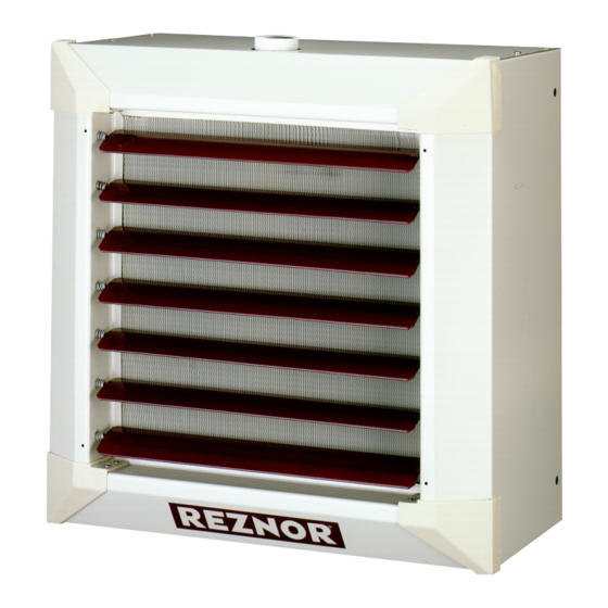
MODEL WS
⚠ WARNING ⚠
Revision: WS-IOM (12-22) 1042506-0
Supersedes: — (Original Version)
Advertisement
Table of Contents

Related Manuals for Reznor WS


Summary of Contents for Reznor WS
- Page 1 Revision: WS-IOM (12-22) 1042506-0 Supersedes: — (Original Version) HYDRONIC UNIT HEATER INSTALLATION, OPERATION, AND MAINTENANCE MODEL WS ⚠ WARNING ⚠ • Be sure to read and understand the installation, operation, and service instructions in this manual. • Installation should be done by a qualified agency in accordance with these instructions. The qualified service agency installing this heater is responsible for the installation.
-
Page 2: Table Of Contents
INSTALLATION RECORD (TO BE COMPLETED BY INSTALLER)........20 WS-IOM (12-22) 1042506-0... -
Page 3: General Information
These unit heaters are listed by Intertek for use in the United States and in Canada . Installation Codes These units must be installed in accordance with local building codes . Local authorities having jurisdiction should be consulted before installation is made to verify local codes and installation procedure requirements . WS-IOM (12-22) 1042506-0... -
Page 4: Heater Location
46 (14) 59 (18) 18 (5 .5) 20 (6) 968 (90) 1184 (110) 300/350 18 (5 .5) 20 (6) 66 (20) 85 (26) 23 (7) 30 (9) 1399 (130) 1722 (160) Maximum mounting height (see Figure 1) . WS-IOM (12-22) 1042506-0... -
Page 5: Acoustical Considerations
Refer to sound level data listed in Table 2 when determining unit location based on acoustical considerations . Table 2. Acoustical Data Unit Size 18/24 23/33 44/62 60/85 78/110 96/120 140/175 190/238 300/350 Speed Sound level (dBa) @ 16-1/2 feet High WS-IOM (12-22) 1042506-0... -
Page 6: Dimensions
Always maintain a minimum clearance of 6 inches (150 mm) behind the unit for maintenance of the motor and fan . Weights Table 4. Weights Unit Size 18/24 23/33 44/62 60/85 78/110 96/120 140/175 190/238 300/350 Pounds (kg) 37 (17) 44 (20) 49 (22) 55 (25) 66 ( 30) 75 (34) 88 (40) 101 (46) 146 (66) WS-IOM (12-22) 1042506-0... -
Page 7: Installation
1 . Position vertical louver assembly (see Figure 3) on face of heater and align existing mounting holes . 2 . Secure vertical louver assembly to heater using fasteners provided in option kit . Figure 3. Vertical Louver Assembly WS-IOM (12-22) 1042506-0... -
Page 8: Installing Airflow Optimizer (Option Hl11)
1 . Determine installation height and secure field-supplied brackets to wall as shown in using field-supplied hardware . Figure 5 2 . Raise heater using suitable hoist or lift and secure heater to brackets as shown in using M8 metric screws and flat washers provided . WS-IOM (12-22) 1042506-0... -
Page 9: Suspending Heater For Horizontal Discharge Using Threaded Rods Or Eyebolts
Figure 6. Suspending Heater for Horizontal Discharge (Refer to Table Table 6. Suspension Point Dimensions Unit Size 18/24, 23/33, 44/62, 60/85 78/110, 96/120, 140/175 190/238, 300/350 Dimension A (Inches (mm)) 4 (102) 4-3/4 (121) 5-1/8 (130) Figure WS-IOM (12-22) 1042506-0... -
Page 10: Suspending Heater For Vertical Discharge Using Suspension Plates
8) sealed with pipe sealant . • Connect hot water piping in accordance with piping diagram shown in Figure • Connect steam piping in accordance with piping diagram shown in Figure 10 . Figure 8. Three-Part Joint Union and Ball Valve WS-IOM (12-22) 1042506-0... - Page 11 Figure 9. Hot Water Piping Diagram STEAM SLOPE SUPPLY STEAM SLOPE CONDENSATE CONDENSATE RETURN SUPPLY FLOW TRAP RETURN DRIP LEG AND FLOW TRAP DRIP LEG CLEANOUT DRAIN CLEANOUT DRAIN HORIZONTAL DISCHARGE VERTICAL DISCHARGE Figure 10. Steam Piping Diagram WS-IOM (12-22) 1042506-0...
-
Page 12: Electrical Connections
NOTE: Internal motor wiring (for reference only): black wire from motor winding connects to U1, red wire from motor winding connects to V1, and green wire from motor winding connects to W1. CAPACITOR MOTOR FIELD- SUPPLIED OVER- MANUAL STARTER LOAD THERMOSTAT HIGH SPEED LOW SPEED Figure 11. Wiring Diagram WS-IOM (12-22) 1042506-0... -
Page 13: Cleaning And Water Treatment
1 . Set thermostat at lowest setting . 2 . Turn ON electric power to heater . 3 . Open hot water or steam supply valve . 4 . Set thermostat to desired setting . Refer to Table 9 for operational sequence . WS-IOM (12-22) 1042506-0... -
Page 14: Fan Speed Adjustment
(2973) (3738) (6457) Air volume Hot water (cfm (m /hr) or steam 1250 1650 1550 2300 2850 4750 High (680) (850) (1461) (2124) (2804) (2634) (3908) (4842) (8071) Hot water Maximum High heating capacity (MBH) Steam High WS-IOM (12-22) 1042506-0... -
Page 15: Louver Adjustment
The unit is designed to operate with a minimum of maintenance . However, to ensure long life and satisfactory performance, routine service is recommended . When servicing, follow standard safety procedures and those specific instructions and warnings in this manual . WS-IOM (12-22) 1042506-0... -
Page 16: Service Checklist
. • Closed motors have self-lubricating bearings and are maintenance-free . If the motor is replaced, don’t forget to check fan rotation . WS-IOM (12-22) 1042506-0... -
Page 17: Troubleshooting
2 . Defective capacitor Replace capacitor 3 . Defective starter Replace starter 4 . Defective overload Replace overload 5 . Defective fan motor Replace motor 6 . Poor airflow Clean motor, fan, and fan guard Clean heat exchanger Adjust louvers WS-IOM (12-22) 1042506-0... - Page 18 NOTES WS-IOM (12-22) 1042506-0...
- Page 19 NOTES WS-IOM (12-22) 1042506-0...
-
Page 20: Installation Record (To Be Completed By Installer)
For more information, contact your Factory Representative. Specifications and illustrations subject to change without notice or incurring obligations . Latest version of this manual is available at www.reznorhvac.com . ©2022 Nortek Global HVAC LLC, O’Fallon, MO . All rights reserved . WS-IOM (12-22) 1042506-0...
Need help?
Do you have a question about the WS and is the answer not in the manual?
Questions and answers