Table of Contents
Advertisement
WARNING:
!
FIRE OR EXPLOSION HAZARD
Failure to follow safety warnings exactly could result in serious injury, death, or
property damage.
Be sure to read and understand the installation, operation, and service instructions in
this manual.
Improper installation, adjustment, alteration, service, or maintenance can cause
serious injury, death, or property damage.
—
Do not store or use gasoline or other flammable vapors and liquids in the vicinity
of this or any other appliance.
—
WHAT TO DO IF YOU SMELL GAS
•
Do not try to light any appliance.
•
Do not touch any electrical switch; do not use any phone in your building.
•
Leave the building immediately.
•
Immediately call your gas supplier from a phone remote from the building. Follow
the gas supplier's instructions.
•
If you cannot reach your gas supplier, call the fire department.
—
Installation and service must be performed by a qualified installer, service agency,
or the gas supplier.
®
®
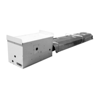
Model VR Burner/Control Box
with 20 - 70 ft Tube/Reflector Length
INSTALLATION / OPERATION / MAINTENANC
Applies to:
Gas-Fired, Tubular, Radiant,
Low-Intensity Infrared Heater
Form I-VR (10-14)
Obsoletes Form I-VR (Version F)
Model VR (std 60 Hz or
optional 50 Hz) and
Model GVR (std 50 Hz)
CQS
CQS
Form I-VR (10-14), P/N 205202 R14, Page 1
E
Advertisement
Table of Contents

Related Manuals for Reznor VR Series


Summary of Contents for Reznor VR Series
- Page 1 Form I-VR (10-14) ® Obsoletes Form I-VR (Version F) INSTALLATION / OPERATION / MAINTENANC Model VR (std 60 Hz or ® Applies to: optional 50 Hz) and Model GVR (std 50 Hz) Gas-Fired, Tubular, Radiant, Low-Intensity Infrared Heater Model VR Burner/Control Box with 20 - 70 ft Tube/Reflector Length WARNING: FIRE OR EXPLOSION HAZARD...
-
Page 2: Table Of Contents
Table of Contents 1. General ..........2-3 7. Electrical and Wiring ....31-32 1.1 Cautions and Warnings ....2 7.1 Wiring Diagram ......32 1.2 Warranty ........3 7.2 Control Thermostat ....32 1.3 Installation Codes ......3 8. Check Installation & Start-Up ..33-34 2. -
Page 3: Warranty
California If the heater is being installed in the state of California, the installer MUST attach a warning label on the outside of the unit. The California Warning Label Warning Label is shipped in the owner’s envelope along with this manual, the warranty form, and any other paperwork that applies. - Page 4 2. Location trial installations only. Do not install these tubular radiant heaters in areas that contain corrosive or toxic fumes or where elements in the atmosphere could (cont’d) produce corrosive or toxic fumes in the presence of an open flame. These heaters do not qualify for explosion-proof installations.
-
Page 5: Uncrating/Packaging
should be located parallel to the wall. The distance from the wall is determined by whether the reflectors will be angled or horizontal. For spot heating applications, the tubular system should be located to direct the rays toward the area requiring heat. Depending on the installation, this can be done from directly overhead or reflector angled from the side. -
Page 6: Configurations, Dimensions, And Clearances
3. Uncrating/ CK11) and/or a turnbuckle kit (Option CK12-18) or field-supplied hardware. See sus- pension requirements in Paragraph 5.) Packaging Accessory Cartons - All field-installed options are shipped in separate car- (cont’d) Packaging Scheme for 10’ Straight Tubes Important NOTE: Before Pkg ID* Pkg P/N Contents... -
Page 7: Dimensions
Configuration With “U” Or With 2 Straight With With 5-ft Tube(s) & Straight “L” Tube “L” Tubes 5-ft Tube “U” Or “L” Tube Allowable Straight Lengths by Size and Configuration (feet) 20, 30, 40 20, 30, 40 20, 30, 40 25, 35 25, 30, 35, 40 20, 30, 40... -
Page 8: Clearances To Combustibles
4. Dimensions, Configurations, and Clearances (cont’d) 4.3 Clearances to Required clearances depend on the size of the heater (BTUH input), the posi- tion of the reflector, and the addition of an optional side shield on the rear side Combustibles of the heater. Refer to illustrations in FIGURE 3 to define clearances. The stated clearance to combustibles represents a surface temperature of 90°F (32°C) above room temperature. -
Page 9: Mechanical
Straight System Length Expansion inches 70 ft 21.3 2-3/4 60 ft 18.3 2-3/8 50 ft 15.2 2-1/8 40 ft 12.2 1-7/8 30 ft 1-1/2 20 ft 1-1/8 Each straight tube section must have a suspension point. Straight sections adjacent downstream to a “U” or “L” tube require two suspension points. There must be a suspension point within 12 inches (305mm) of every coupler. -
Page 10: Combustion Air
6. Mechanical (cont’d) 6.1 Prepare the Burner/Control Box (cont’d) FIGURE 4 - Change the Combustion Air Restrictor Plate Combustion Air • 1st, remove and discard the factory Restrictor Plate installed restrictor plate. (Save the nuts.) • 2nd, attach the restrictor plate from the conversion parts bag. -
Page 11: Assemble & Suspend Heater
Additional Burner If a Model VR/GVR 50-175 is being installed at an altitude above 6000 ft Box Preparation for (1830M), the pressure switch will have to be changed. If ordered with the unit as Option DJ20, the pressure switch is shipped separately. (NOTE: Model Operation Above VR200 does not require a pressure switch change above 6000 ft/1830M.) 6000 ft (1830M) - Page 12 6. Mechanical 6.2.2 Suspend the Assembled Burner/Control Box and Combustion Chamber Tube (cont’d) (cont’d) FIGURE 9 - 6.2 Assemble and Wire Reflector Suspend the Wire Reflector Retainer and Heater (cont’d) Retainer, Hanger Bar Hanger Bar, NOTE: One “hook” of the and Tube wire retainer is bent 75°...
- Page 13 FIGURE 12 - Chain attached to suspension point. Attaching Hanging Chain at Tube “S” Hook Hanger Bar Suspension Points NOTE: Reflectors shown here will be installed after all chains are in place. There are very important steps that must be followed to suspend and assemble 6.2.3 Install the Heat this tubular radiant heater.
- Page 14 6. Mechanical 6.2.3 Install the Heat Exchanger Tubes and Turbulator Strip (cont’d) Sections (cont’d) with nuts. (NOTE: Nuts must be secure before heater is operated, but if the 6.2 Assemble and reflector is going to be rotated, nuts may be installed loosely now and tight- Suspend the ened later.) Heater (cont’d)
- Page 15 FIGURES 16A and Figure 16A - Turbulator Figure 16B - As turbulator strip is 16B - Interlocking Strip Sections installed in the tube, interlock the Turbulator Strip sections. Sections Turbulator Requirements Configuration Turbulator Sections (Some sections may not be used; follow instructions.) Length BTUH In Tube...
- Page 16 6. Mechanical 6.2 Assemble and Suspend the Heater (cont’d) (cont’d) 6.2.3 Install the Heat Exchanger Tubes and Turbulator Strip Sections (cont’d) Turbulator Requirements (cont’d) FIGURE 17A - Examples of configurations Slide all turburlator sections with the exhaust heat exchanger tube into exhaust heat exchanger tube adjacent to a straight heat exchanger.
- Page 17 NON-SLIP overlaps are required at each end of the “U” or “L” tube reflector. • No more than five consecutive NON-SLIP overlaps in a section con- taining two “L” tube reflectors. NOTE: Four of the five overlaps are required at each end of the “L” tube reflectors. •...
- Page 18 6. Mechanical Straight Tube Reflector Installation Instructions (cont’d) (cont’d) 7. SLIP Overlap (One on 40 & 50 ft systems and two on 60 & 70 ft systems) 6.2 Assemble and Install reflector with a 1-1/2” (38mm) overlap. Do not screw the reflectors Suspend the together.
- Page 19 Side Shield Because side shields can be installed anywhere along the tube length and use the same wire reflector retainers and tube brackets as the tubes, the side Installation shield hanger slots must be made in the field to match the system. Therefore, Instructions the first hanger slot location is shown in FIGURE 20.
-
Page 20: Gas Piping And Pressures
6. Mechanical 6.2.4 Install Reflectors and Optional Side Shield and/or End Covers (cont’d) (cont’d) • Reflectors on straight systems with a side shield may be angled 15° or 30°. 6.2 Assemble and The side shield must hang vertically. Suspend the •... - Page 21 WARNING: This appliance is equipped for a maximum gas supply pressure of 1/2 pound, 8 ounces, or 14 inches water column. NOTE: Supply pressure higher than 1/2 pound requires installation of an additional service regulator external to the unit. PRESSURE TESTING SUPPLY PIPING Test Pressures Above 1/2 PSI: Disconnect the heater and manual valve from the gas supply line which is to be tested.
-
Page 22: Installation Requirements
6. Mechanical 6.3 Gas Piping and Pressures (cont’d) (cont’d) Use a joint compound that is resistant to propane gas at all connections. Test all gas lines using a leak-detecting solution. FIGURE 23 - Gas Connection THE GAS SUPPLY NIPPLE MUST BE PARALLEL TO THE HEATER MOVEMENT Installation Requirements VERTICAL... -
Page 23: Startup Procedures
But if adjustment is required, set pressure to correct settings by turning the regulator screw IN (clockwise) to increase pressure. Turn regulator screw OUT (counterclockwise) to decrease pressure. Remove manometer, replace the cap, and check for leak at pressure tap. CAUTION: DO NOT bottom out the gas valve regulator adjusting screw. -
Page 24: Venting And Combustion Air
6. Mechanical and 14” w.c. for Sizes 175-200. For propane gas, the inlet pressure must be between 11” and 14” w.c. Take this reading as close as possible to the (cont’d) heater (Heaters are equipped with gas valves that have an inlet pressure tap.) If the inlet pressure is not within the specified range, the inlet pressure 6.3 Gas Piping must be corrected and Steps 3 and 4 repeated. - Page 25 surrounding ambient temperature is 60°F unless otherwise noted (See Vent Requirement No. 6, Condensation). Do not exceed maximum vent length. Minimum vent length is 5 feet (1.5M). Vent Length Table Vent Length Table for Tubular Infrared Heaters Equivalent Length for Vent Length Input Vent...
- Page 26 7. Vent Terminal and Vent Cap - The vent terminal and vent cap must be the same diameter as the vent run. Terminate the vent system with a Reznor Option CC1 vent cap. A different style vent cap could cause nuisance problems and/or unsafe conditions.
- Page 27 Products of combustion can cause discoloration of some building finishes and deterioration of masonry materials. Applying a clear silicone sealant that is normally used to protect concrete driveways can protect masonry materials. If discoloration is an esthetic problem, relocate the vent or install a vertical vent. Horizontal Vent Minimum Clearances for Vent Termination Structure...
- Page 28 6. Mechanical 6.4 Venting and Combustion Air (cont’d) (cont’d) 6.4.1 Specific Venting Requirements (cont’d) Vertical Vent and Inlet Air Terminals FIGURE 27A - Vertical Vent Terminal Arrangements (drawings are not proportional; read all information) SINGLE WALL - Single wall vent run and DOUBLE WALL - Single wall vent run and single wall terminal end double wall terminal end...
- Page 29 Dual Vent Terminal Arrangements with Option CC5 FIGURE 28A - Vertical Dual Single-wall outer dual vent pipe Vent Terminal Single-wall inner dual vent pipe Arrangement 6 ft (1.8M) minimum Vertical extension must be 6” (152mm) higher than anticipated 6 ft snow depth but not less than 24”...
- Page 30 6. Mechanical 6.4.3 Unvented Installation (cont’d) (cont’d) DANGER: The fresh air requirement of 4 CFM per 1000 BTUH 6.4 Venting and for natural gas and 5 CFM per 1000 BTUH for propane gas is Combustion Air mandatory when operating a heater in the unvented mode. See (cont’d) Hazard Levels, page 2.
-
Page 31: Electrical And Wiring
1. Air from inside building -- openings 1 square inch free area per 1000 BTUH. Never less than 100 square inches free area for each opening. See (1) in FIGURE 30. 2. Air from outside through duct -- openings 1 square inch free area per 2000 BTUH. -
Page 32: Wiring Diagram
8. FOR UNVENTED INSTALLATIONS WHEN MECHANICAL MEANS IS PROVIDED TO SUPPLY AND EXHAUST, A POSITIVE INTERLOCK MUST BE PROVIDED BY THE INSTALLER SO THAT THE HEATER CANNOT OPERATE UNLESS THE SUPPLY AND VR SERIES WD# 204374 REV. #3 EXHAUST SYSTEM IS OPERATING. -
Page 33: Check Installation & Start-Up
FIGURE 32 - Thermostat Connections Terminal Strip on the Burner Box for Thermostat Connections of the infrared rays. See the wiring diagram in FIGURE 31 or inside the heater door panel. Unit-Mounted Thermostat Bracket, Option CM3 The optional thermostat bracket kit allows attachment of the controlling ther- mostat to the burner/control box. - Page 34 8. Check Start-Up: Installation Bleed all air from the gas supply lines to the heater. Rotate the knob on the and Start-Up combination valve to the "ON" position. (cont’d) Set the thermostat to above room temperature. This heater is equipped with a fully automatic ignition;...
-
Page 35: Maintenance
9. Maintenance 9.1 Maintenance Requirements As with any gas-burning equipment, regular maintenance procedures are required to ensure continued safety, reliability, and efficiency of the installa- tion. If service is required, this heater should be serviced only by a qualified service person. - Page 36 9. Maintenance (cont’d) 9.2 Maintenance Procedures (cont’d) 9.2.4 Vent Pipe During a “cold” startup, transient condensation is formed. Over a period of time, condensation will cause metal pipe to develop holes and eventually fail completely. Replace any vent pipe that has condensation damage. The vent pipe system should be maintained at a quality where all flue products will be conveyed through the vent pipe to the outdoors.
- Page 37 FIGURE 34 - Remove Combustion FIGURE 35 - Air Restrictor Plate Clean the Blower Wheel Blower Wheel Clean the blower wheel using a brush, low- pressure compressed air, and an aerosol degreaser or refrigerant coil cleaner. Be careful not to damage Combustion Air the blower wheel.
- Page 38 9. Maintenance 9.2 Maintenance Procedures (cont’d) (cont’d) 9.2.8 Main Burner (cont’d) FIGURE 36A - Open the Burner Compartment and Remove the Burner First, remove these two Brass Nut screws. Then, supporting the front of the burner, remove the brass nut at the other end.
-
Page 39: Service
FIGURE 37A - Spark FIGURE 37B - Electrode Assembly as Remove Spark seen through the front of Electrode the box (only visible when Assembly the combustion chamber is not attached.) Remove the screw and carefully remove Spark the spark Electrode electrode Assembly assembly. - Page 40 10. Service (cont’d) Pressure Switch Function - The pressure switch is a safety control to ensure that adequate air 10.1 Control is being provided for proper combustion. The device “senses” a small differen- Location, tial pressure created by the flow of the combustion air. Operation, Sensing Pressure Check (requires a Phillips screwdriver, a sensitive slope and Service...
- Page 41 Ignition Controller Function - The ignition controller functions to ignite the burner and as a flame supervision device. The ignition controller will shut off main burner gas flow FIGURE 40 - immediately if the burner flame is lost. Ignition Controller Burner ignition is achieved by a high voltage (18kV) spark that occurs across the spark electrode.
-
Page 42: Troubleshooting
10. Service (cont’d) 10.2 Troubleshooting WARNING: Service work on this heater should only be done by a qualified gas service person. All service information including the Troubleshooting Guides is intended as an aid to a qualified service person. Check the Light on the DSI Control Board The DSI control board monitors the operation LED Codes of the heater and includes a LED signal light... - Page 43 PROBLEM PROBABLE CAUSE REMEDY Burner cycles 1. Gas pressure too high or too low. 1. See Gas Supply Pressure Table, Paragraph 6.3. on and off 2. DSI control board not grounded. 2. Make certain DSI control board is grounded to furnace chassis. 3.
-
Page 44: Pressure Switch
10. Service (cont’d) Is the gas Open all manual gas valves 10.2 Troubleshooting (cont’d) supply turned in the supply line to the heater. Rotate the knob on the combination valve to the "ON" position. FIGURE 45 - Correct supply prssure by adjusting field-supplied Is the gas supply Basic... -
Page 45: Addendum
Addendum Instructions for Attaching Double-Wall Vent Pipe (Type-B) FIGURE 47 - STEP 1 FIGURE 47 - STEP 2 FIGURE 47 - Attaching Double- On the single-wall pipe, where illus- Insert the single-wall pipe into the trated, place a continual 1/4 inch Wall (Type B) Pipe to inner pipe of the double-wall pipe bead of silicone sealant around the... -
Page 46: Technical Information
Addendum Model VR/GVR Technical Information (cont’d) Electrical Model VR (std 60 Hertz) Characteristics Voltage/Phase Standard 115/1; Optional 208/1, 230/1 Frequency 60 hertz Control Amps (24V) Main Burner Ignition Direct Spark Sizes 50, 75, Sizes 125 Full Load Amps Size 175 Size 200 and 100 and 150... -
Page 47: Index
Index Gas Piping and Pressures 20 “U” or “L” Tube Reflectors 18 Gas Pressure 46 Reflectors 16 Gas Supply Pressure Table 20 Wire Reflector Retainer 12 Accessory Cartons 6 Gas Valve 22, 39, 41 Addendum 45 General 2 “S” Hook 13 Angle Reflectors 20 Service 39 Assemble the Burner/Control Box and... -
Page 48: Installer Must Complete
ZI de Rosarge - 230 Rue de la Dombes Mercer, PA 16137 Les Echets - 01706 Miribel cedex United States France gazindustrie@gazindustrie.fr ©2014 Reznor LLC, All rights reserved. Trademark Notes: Reznor and SUPERSTRUT are registered in ® ® at least the United States.
Need help?
Do you have a question about the VR Series and is the answer not in the manual?
Questions and answers