Table of Contents
Advertisement
Quick Links
GAS FIRED BALANCED FLUE / FAN ASSISTED FLUE
Please read this document carefully before commencing installation, commissioning and/or servicing.
Leave it with the user or attached to the appliance or gas service meter after installation.
Improper installation, adjustment, alteration, service or maintenance can cause property damage, injury or death. All work
must be carried out by appropriately qualified persons.
The manufacturer does not take any responsibility in the event of non-observance of the regulations concerning the
connection of the apparatus causing an evil operation possibly resulting in damage to the apparatus and/or environment in
which the unit is installed.
Subject to modifications
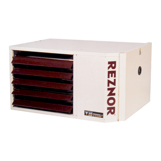
UNIT HEATER
UDSA-4E
INSTALLATION
COMMISSIONING
SERVICING
These appliances meet the following EC Directives
DIR 2009/142/EC:GAD
DIR 2014/30/EU:EMC
DIR 2014/35/EU: LVD
DIR 2006/42/EC:MD
WARNING
1711UDSA-4E_GBEN
1711UDSA-4EGBEN, Pag. 1/32
Advertisement
Table of Contents

Related Manuals for Reznor NORTEK UDSA-4E


Summary of Contents for Reznor NORTEK UDSA-4E
- Page 1 1711UDSA-4E_GBEN GAS FIRED BALANCED FLUE / FAN ASSISTED FLUE UNIT HEATER UDSA-4E INSTALLATION COMMISSIONING SERVICING These appliances meet the following EC Directives DIR 2009/142/EC:GAD DIR 2014/30/EU:EMC DIR 2014/35/EU: LVD DIR 2006/42/EC:MD Please read this document carefully before commencing installation, commissioning and/or servicing. Leave it with the user or attached to the appliance or gas service meter after installation.
-
Page 2: Installation Codes
INDEX GENERAL Warnings 1. General Models UDSA-4E are design certified to the CE EN1020 2. Installation codes standard for use in industrial and commercial installations 3. Warranty only. All models and sizes are available for use with either 4. Uncrating and preparation natural or propane gas. - Page 3 DIMENSIONS/CLEARANCES (horizontal orientation=standard) Figure 1 Rear view (only mod. 035,043,050) view Side view Rear view (all mod. except 035,043,050) Front view 1. Combustion air inlet 2. Flue connection 3. External gas connection 4. Electrical connections 5. Service panel Table 1 : Dimensions (mm) UDSA-4E 15,5 015-020...
- Page 4 Clearances (mm) Attention : Units must be installed so that the minimum clearances in the following table are provided for combustion air The clearance distance from the flue system must be space, inspection and service and for proper spacing from minimum 150mm at all points ! combustible materials.
-
Page 5: Technical Data
TECHNICAL DATA Table 4 : Technical data 1711UDSA-4EGBEN, Pag. 5/32... -
Page 6: Flue Requirements
FLUE REQUIREMENTS IMPORTANT : The air heaters may be installed as a balanced flue (type C) heater requiring both a combustion air inlet duct and a flue The flue must be installed in accordance with national pipe or as a power vented heater (type B) (the combustion and local regulations. - Page 7 FLUE OUTLET Figure 3 : Type B appliances : Combustion air and flue pipe sockets Venter outlet attachment requirements: Depending on the size of flue pipe as determined in table 5, All mod. exc. 035-4E, 043-4E, 050-4E & 100-4E attach either the flue pipe directly to the collar or a taper-type connector.
- Page 8 AIR SUPPLY Warning: Always ensure that adequate combustion air is provided When these air heaters are installed in type B applica- to suit the total installation of all combustion equipment tions, designed to take air for combustion from the in accordance with BS6230 or BS5440 as appropriate. space in which it is installed.
-
Page 9: Hanging The Heater
LOCATION HEATER Warning: At those points where infiltration of cold air is excessive, such as at entrance doors and shipping doors, it is desirable to locate If touched, the vent pipe and internal heater surfaces that are the unit so that it will discharge directly toward the source of accessible from outside the heater will cause burns. -
Page 10: Gas Piping & Pressures
When desired the heaters may be supported by wall brackets. There are 2 different wall bracket designs for UDSA-4E models Supporting in this manner allows the heaters to be placed in as shown in the illustrations below. close proximity to the ceiling or mounted directly to the vertical Mounting instructions are detailed in the literature supplied supporting structures of the building. -
Page 11: Electrical Connection
ELECTRICAL CONNECTION MPORTANT: DANGER : THIS APPLIANCE MUST BE If the reset button requires activating for any reason, EARTHED. the cause must be determined. After determining and correcting the problem, restart the heater and monitor long enough to ensure proper operation (approx. 5 The electrical installation may only be carried out by an minutes). - Page 12 WIRING DIAGRAM (for illustrative purposes) 1711UDSA-4EGBEN, Pag. 12/32...
- Page 13 START-UP Check the installation prior to start-up Thermostat calls for heat, energyzing the venter motor. 10. When adequate air flow for combustion is proven by an Check suspension. Unit must be secure.Verify that no other air proving switch and a prepurge period has elapsed, parts are fitted which are not individually supported and the integral ignitor and multifunctional gas control op- secured.
- Page 14 Burner gas pressure adjustment The gas pressure is set for the required heat input before the Observe the burner gas pressure on the manometer and appliance leaves the factory. Provided that the gas supply compare to the required pressure on the data plate; to the air heater is in accordance with the supply pressure If necessary, adjust the burner gas pressure.
- Page 15 IGNITION SYSTEM This heater is equipped with a direct spark integrated control relay. The control relay monitors the safety devices and controls the operation of the venter motor and the gas valve between heat cycles. The time line below illustrates a normal heat cycle.
-
Page 16: Maintenance & Service
MAINTENANCE/SERVICE Warning : spected and cleaned at the start of each heating season (in- spection and maintenance at least once a year). If the heater is If you turn off the power supply, always turn off the gas. operating in an area where an unusual amount of dust or other The material contained in the MAINTENANCE AND SERVICE impurities are present in the air, more frequent maintenance Section of this manual is designed to aid a qualified service... -
Page 17: Heat Exchanger Maintenance
Figure 11b - Control panel assy located on a removable bracket 1) Control relay (ER) 2) Terminal blocks 3) Pressure switch (S3) 4) Electronic burner relay fuse 3.15AF HEAT EXCHANGER MAINTENANCE This heater is equipped with a patented T-CORE heat exchanger. 2®... -
Page 18: Burner Maintenance
BURNER MAINTENANCE This heater has a unique one-piece T-CORE burner assembly Inspect the burner/control compartment annually to determine 2® designed to provide controlled flame stability without lifting or if cleaning is necessary. If there is an accumulation of dirt, dust, flashback. -
Page 19: Burner Orifice
Figure 14 - Burner removal steps BURNER ORIFICE 2. Remove screws attaching burner The burner orifice normally needs to be replaced only when a change in gas is made. When ordering a replacement orifice, provide (MJ/m ) heating value and specific gravity of gas, as well as the model and serial number of the unit. -
Page 20: Fan Motors
Flame sensor - Refer to figure 11a and locate the flame Figure 17 - Control relay Brahma TC340A sensor. Disconnect the wire, remove the screw and the flame sensor. Clean with an emery cloth.. Control relay - See figure 17. The electronic burner relay monitors the operation of the heater including ignition. - Page 21 VENTER MOTOR & WHEEL Figure 18b Remove dirt and grease from the motor casing, the venter housing, and the venter wheel. Venter motor bearings are UDSA-4E mod. 025 - 030 permanently lubricated. (Rotation clockwise from motor shaft end) Follow these instructions for replacement of the venter motor and wheel assembly.
-
Page 22: Limit Controls
OPERATING GAS VALVE LIMIT CONTROLS The main operating quick opening gas valve is powered through All units are equipped with temperature activated limit controls. the thermostat and safety controls. The main control valve is of The controls are factory set and non-adjustable. If either set- the diaphragm type providing regulated gas flow and is preset at point is reached, the corresponding limit control will interrupt the factory. -
Page 23: Troubleshooting
TROUBLESHOOTING The integrated control relay monitors the operation of the heater. If the heater fails to operate properly, review the flow chart below and see the operating sequence in section 16. The general troubleshooting charts on the following pages will also help you to determine the problem. 1/ Air heater does not operate and lock-out indicator light is off 1711UDSA-4EGBEN, Pag. - Page 24 2/ Air heater does not operate and lock-out indicator light is on 1711UDSA-4EGBEN, Pag. 24/32...
- Page 25 1711UDSA-4EGBEN, Pag. 25/32...
- Page 26 1711UDSA-4EGBEN, Pag. 26/32...
- Page 27 1711UDSA-4EGBEN, Pag. 27/32...
-
Page 28: General Troubleshooting
General troubleshooting PROBLEM PROBABLE CAUSE REMEDY Venter motor 1. No power to unit 1. Turn on power, check supply fuses or circuit breaker. will not start 2. No power to venter motor 2. Check connections at burner relay and/or venter motor terminals. 3. - Page 29 25. Parts list Description UDSA-4E Part number Control relay 03 25321 Spark ignitor 05 25162 Flame sensor 03 401US 195292 Limit control LC3 03 24959 03 Limit control LC1 03 24959 04 Pressure switch 030’ 30 60621 100 Pressure switch 035’...
- Page 30 CERTIFICATE EC DECLARATION OF CONFORMITY OF MACHINERY (Annex II 1 A of EC Machinery Directive 2006/42/EC) Nortek Global HVAC Belgium nv J&M Sabbestraat 130/A000 B-8930 Menen, Belgium Hereby declares that the following gas-fired unit heaters: UDSA-4E Types 011, 015, 020, 025, 030, 035, 043, 050, 055, 064, 073, 085, 100 Complies with the requirements of the above mentioned machinery directive Complies with the requirements of further directives, namely GAD 2009/142/EC - EMC 2014/30/EU –...
- Page 31 1711UDSA-4EGBEN, Pag. 31/32...
- Page 32 Tel 01384 489250 Fax 01384 489707 reznorsales@nortek.com www.reznor.co.uk Nortek Global HVAC is a registered trademark of the Nortek Global HVAC limited. Because of the continuous product innovation Nortek Global HVAC reserves the right to change product specification without due notice.
Need help?
Do you have a question about the NORTEK UDSA-4E and is the answer not in the manual?
Questions and answers