
Related Manuals for Endress+Hauser Liquisys CUM 252


Summary of Contents for Endress+Hauser Liquisys CUM 252
- Page 1 BA 174C/07/en/01.98 liquisys No. 50088699 Software version 1.0 or later CUM 252 Transmitter for Turbidity and Solids Content Operating Instructions Endress Hauser Nothing beats know-how...
- Page 2 Please familiarise yourself with the instrument before you take any other steps: General information Safety Description You wish to install and start up the instrument. The required steps are described in these chapters: Installation First start-up You wish to operate or reconfigure the instrument. The operating concept is explained in these chapters: Operation Instrument configuration...
-
Page 3: Table Of Contents
CUM 252 Table of contents Table of contents General information ....... . . 2 Symbols used . -
Page 4: General Information
This symbol alerts to possible malfunction due to operator error. Note: This symbol indicates important items of information. Conformity statement The Liquisys CUM 252 measuring transmitter has been developed and manufactured in accordance with the applicable European standards and directives. Note: The corresponding certificate of conformity may be requested from Endress+Hauser. -
Page 5: Safety
Installation, start-up, operation The Liquisys CUM 252 instrument has been designed for safe operation according to the state of the art in engineering and in keeping with the applicable regulations and EC directives; see “Technical data”. -
Page 6: Instrument Description
Instrument description liquisys CUM 252 Instrument description Areas of application The measuring transmitter Liquisys CUM 252 is an excellent choice for measuring and control tasks in the following areas of application: Sewage treatment plants, solids concentration measurement Effluent treatment Water treatment and water monitoring... -
Page 7: Essential Features
(shielded standard cable / 2 × 2 wires, twisted pair) with junction box VBM if necessary the Liquisys CUM 252 measuring transmitter Essential features Field housing with protection type IP 65 Measuring ranges 0 ... -
Page 8: Instrument Variants
Additional features Base version Moisture protection lacquering Special version to customer specifications You can identify the device variant and the mains supply type by the order code on the nameplate of the instrument. Fig. 3.2 Nameplate of Liquisys CUM 252 Endress+Hauser... -
Page 9: Accessories
CUM 252 Instrument description Accessories Sensor Type Features Areas of application CUS 31 Scattered light sensor in all-plastic housing Drinking water, with sapphire windows and perm. attached surface water, cable, cable length optionally 7 or 15 m, service water, prot. -
Page 10: Installation
Save the original packaging in case the device must be stored or shipped at a later time. If you have any questions, please consult your supplier or the Endress+Hauser sales office in your area (see back cover of these operating instructions for addresses). -
Page 11: Mounting
Fig. 4.1 Wall mounting of Liquisys CUM 252 Post mounting of Liquisys CUM 252 in field housing (optional) Additional requirements: post mounting kit (see Mounting accessories). Install the post mounting kit on the rear of the instrument. Installation is possible on horizontal or vertical piping. The maximum pipe diameter is 60 mm (see figure 4.2). - Page 12 Installation liquisys CUM 252 Mounting accessories Post mounting kit Kit for installation of field housing on horizontal or vertical pipes (max. ∅ 60 mm); Material: stainless steel VA; order no. 50086842 ∅ 8 ∅ 8 Fig. 4.3 Post mounting kit...
-
Page 13: Connection
CUM 252 Installation Connection Warning: The connection to the mains may only be established by properly trained specialist personnel. Do not perform service work on the instrument while the instrument is energised. The instrument must be grounded before start-up! A clearly identified mains disconnecting device must be installed close to the instrument. - Page 14 Signal output 2: temp. *) optional Fig. 4.6 Electrical connection of Liquisys CUM 252 Caution: Do not connect the two signal outputs with each other! If you want to connect them both to a PLC with common ground of all inputs, then you must anew isolate one output galvanically.
-
Page 15: Packaging And Disposal
CUM 252 Installation Connection of sensor CUS 31 or CUS 41 The sensor is connected via the multi-core measuring cable attached to the sensor. Should it become necessary to extend the measuring cable, use junction box VBM and a shielded twisted pair cable with 2 ×... -
Page 16: First Start-Up
First start-up liquisys CUM 252 First start-up Connect a type CUS 31 or CUS 41 sensor to the CUM 252 transmitter. After power-up, the measuring chain is ready to measure turbidity (in FNU units) without requiring calibration. If you intend to measure the solids concentration in ppm, g/l or %, you should select the measured quantity/unit and the calibration data set after power-up (see chapters 7.1 and 7.4), and then... - Page 17 CUM 252 First start-up Factory settings The following factory settings are active when the instrument is powered up for the first time: Turbidity measurement in FNU Type of measurement Temperature offset / 0 °C 0 FNU turbidity offset Limit 1...
-
Page 18: Operation
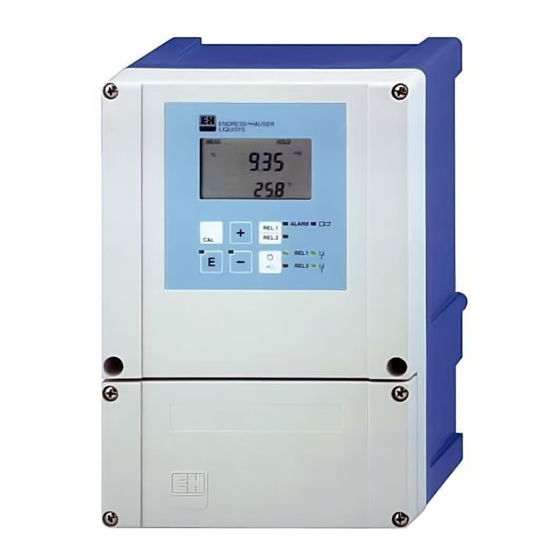
Fig. 6.1 Operating elements of Liquisys CUM 252 Display elements LED indicators Indication for relay controlled in “manual” mode (red LED). Indication for “auto” (green LED) or “manual” (yellow LED) mode. Indicates the status of relays 1 and 2. - Page 19 “Process medium” symbol: “ATC”: indicator temperature Flashes in case of sensor or Flashes in case of In setup / calibr. mode: process alarm together with temperature error e.g. parameter setting sensor symbol Fig. 6.2 Liquid crystal display of Liquisys CUM 252 Endress+Hauser...
-
Page 20: Key Functions
Operation liquisys CUM 252 Key functions Quick calibration Press the CAL key and enter the access code for quick calibration (11) to directly access the calibration mode. Setup After pressing the E key and entering the setup code (22), the instrument switches to the setup mode. -
Page 21: Operating Concept
CUM 252 Operation Operating concept Operating modes Measuring mode Standard mode of operation, display of current measured values Code: Setup mode Read mode Quick calibration mode (3-pt. calibration) Access to all configuration All settings can be read Execution of calibration and calibration menus. - Page 22 Operation liquisys CUM 252 Menu structure The configuration and calibration functions are arranged in a menu structure by function groups. Note: See the fold-out back page of these operating instructions for an overview of the Liquisys menu structure. The function groups are selected in the setup mode with the “+” and “–” keys.
-
Page 23: Operation Example
CUM 252 Operation Hold function: “freezing” of outputs The current output is “frozen” in the setup mode and during quick calibration, i.e. the last current value is constantly output. The display shows the “HOLD” message. During automatic operation, all contacts will go to their normal positions. Any alarm delay accumulated will be reset to “0”. - Page 24 Operation liquisys CUM 252 Select function group “setpoint 2” (SP 2). Select the “Set Limit” function. Change the setting, e.g. from 200.0 FNU to 120.0 FNU. Confirm the entry. The instrument advances to the next function. Change the factory setting of “Hi”...
-
Page 25: Auto / Manual Operating Mode
CUM 252 Operation Return to the measuring mode by pressing the “+” and “–” keys at the same time. The hold function is deactivated. Select the “Setup Code” field. Change the code (to any number) to block the access to the configuration function. - Page 26 Operation liquisys CUM 252 Switching to manual mode The instrument is switched to the manual mode by pressing the Auto / Manual key. In this mode, the relays and a wiper (if present on the sensor) can be switched on and off manually with the “+”...
-
Page 27: Instrument Configuration
CUM 252 Instrument configuration Instrument configuration Measuring point configuration This function group is used to select the measured quantity (application range) and to configure the relay and cleaning functions. Field Selection / range Display Info Turbidity: Selects the quantity The measuring 0 ... - Page 28 Instrument configuration liquisys CUM 252 Field Selection / range Display Info 3 ... 600 s Entry of cleaning time for wiper and spray cleaning system These fields are (On.t = cleaning time not shown when = period during which wiper...
-
Page 29: Limit Contactor Configuration
CUM 252 Instrument configuration Limit contactor configuration These function groups are used to configure the limit parameters. Programming for limits 1 and 2 is the same and is therefore only described once. Characteristic of limit contactors MIN function (Lo) - Page 30 Instrument configuration liquisys CUM 252 Field Selection / range Display Info 0 ... upper range Entry of limit for limit value contactor 1 / 2, depending on measuring range selected, in FNU, ppm, Default: g/l, % Limit 1: 0.00 FNU, ppm,...
-
Page 31: Current Output Range Selection
CUM 252 Instrument configuration Current output range selection This function group is used to determine the range for the current output(s). Field Selection / range Display Info 0 – 20 mA Toggles the lower current 4 – 20 mA... -
Page 32: General Instrument Configuration
Instrument configuration liquisys CUM 252 General instrument configuration This function group is used for general instrument configuration settings. Field Selection / range Display Info Entry of filter time T of the 0 ... 120 s floating measured value filter with PT1 behaviour, step –t / T... - Page 33 CUM 252 Instrument configuration Field Selection / range Display Info Use this function to restore the factory settings for all transmitter functions. (no = do not restore) (YES = restore) (dEF = defaults = factory settings) Default: no Warning:...
-
Page 34: Calibration Adaptation
Instrument configuration liquisys CUM 252 Calibration adaptation This function group is used to adapt the current calibration characteristic following completion of the 3-point calibration. 1-point adaptation for samples with elevated concentrations Adaptation of characteristic in g/l or % measuring range to any concentration with sensor immersed in sample (1-point adaptation), e.g. - Page 35 CUM 252 Instrument configuration Reflection adaptation for low-turbidity samples Adaptation to an installation condition where reflection on pipeline or assembly walls at low turbidities is possible, causing incorrect measurement results (minimum pipe diameter with reflecting inside pipe wall should be DN 100 or sensor should be installed at appropriate distance from wall).
-
Page 36: 3-Point Calibration Of Transmitter
Instrument configuration liquisys CUM 252 3-point calibration of transmitter This function group is used to calibrate the transmitter. Calibration overview The calibration of the measuring chain is a 3-point calibration in all cases, i.e. the entire calibration characteristic of the measuring chain for the process medium is computed by the CUM 252 transmitter based on three medium samples of known turbidity or known solids concentration. - Page 37 CUM 252 Instrument configuration Calibration options The CUM 252 transmitter offers several options for 3-point calibration in this function group. In the first field of the function group, you can select among three calibration functions: Selection “SEnS”: (function 1) 3-point wet calibration with three samples of known or estimated concentration.
- Page 38 Instrument configuration liquisys CUM 252 Description Display Info Immerse the sensor in the sample with the medium concentration, preferably of original sample concentration. A value of Concentration values 3.3⋅calibration value1 is suggested between 1.1⋅calibration on the display. If the sample has...
- Page 39 CUM 252 Instrument configuration Caution: The characteristic computed during the 3-point calibration is stored in the currently selected calibration data set (see function group “ConF”, General instrument settings). If a read-only calibration data set is selected, calibration is not possible.
-
Page 40: Calibration Result Data
Instrument configuration liquisys CUM 252 Entry of exact concentration value for original sample (function 3) Description Display Info Select function “Corr” in first field of function group, confirm with “E”. Entry of concentration value of A concentration value undiluted original sample with “+”... - Page 41 CUM 252 Instrument configuration Field Selection/range Display Info Display of relative 10.0 ... 500.0% calibration result for calibration point1 (Pt.1 = calibration point1) Display of relative 10.0 ... 500.0% calibration result for calibration point2 (Pt.2 = calibration point2) Display of relative 10.0 ...
-
Page 42: Diagnostics
Diagnostics liquisys CUM 252 Diagnostics Warning: Alarm signalling devices must have an independent power supply to permit alarm signalling in the event of a power failure! Limit alarm An alarm condition exists when the measured value – exceeds the upper limit or –... - Page 43 Alarm contact (41 / 42) is closed Hold function is activated If the system error cannot be eliminated by switching the power supply to the instrument off and back on, the instrument must be sent to the competent Endress+Hauser sales agency for servicing. Endress+Hauser...
-
Page 44: Possible Faults In Measuring Mode And Elimination
Diagnostics liquisys CUM 252 Possible faults in measuring mode and elimination Test Remedy No display, no sensor response Transmitter supplied with power? Apply mains voltage Sensor connected to transmitter? Connect sensor Considerable fluctuation of display value No homogeneous sample/medium flow... -
Page 45: Maintenance And Service
(bayonet lock), replace the fuse and reinstall the cap. Further repairs Further repairs may only be carried out directly by the manufacturer or through the Endress+Hauser service organisation. An overview of the Endress+Hauser service network can be found on the back cover of these operating instructions. Endress+Hauser... -
Page 46: Appendix
Appendix liquisys CUM 252 Appendix 10.1 Technical data Turbidity and solids concentration measurement with sensor CUS 31, CUS 41 Display and measuring range Sensor CUS 31 ... . 0 ... 9999 FNU, 0 ... 3000 ppm, 0 ... 3 g/l, 0 ... 200% Sensor CUS 41 . - Page 47 CUM 252 Appendix Alarm function Alarm delay ........0 ... 2000 s Contact function (switchable) .
- Page 48 Appendix liquisys CUM 252 General technical data Measured value display ..LC display, two lines, 4 and 3½ digits, with status indicators Electromagnetic compatibility (EMC) Emission ......acc. to EN 50081-1:1992 Immunity .
-
Page 49: 10.2 Index
CUM 252 Appendix 10.2 Index Access code ....3, 18 Electrical connection ..11-13 Accessories ....7 Electrical data . - Page 50 Appendix liquisys CUM 252 Mains disconnecting device ..11 Safety devices ....3 Mains frequency ... . . 45 Safety notes .
- Page 51 CUM 252 Appendix Display Abbreviation for Meaning Page alarm contact Alarm contact alarm delay Alarm delay application Application range calibration Function group Calibration 32-37 calibration code Calibration code clean hold Clean hold time cleaner Wiper control on/off 24, 25...
- Page 52 Appendix liquisys CUM 252 Display Abbreviation for Meaning Page filter Filter time Function group Measured value adaptation fleeting contact Fleeting contact Max contact, limit monitoring high 22, 28 with upper threshold hysteresis Hysteresis 22, 28 1 point 1-point adaptation Relay selection, limit contact.limit contact...
- Page 53 CUM 252 Appendix Display Abbreviation for Meaning Page point 1 Point 1 of 3-point calibration 34, 36, 38 point 2 Point 2 of 3-point calibration 35, 36, 38 point 3 Point 3 of 3-point calibration 35, 36, 38 reflection...
- Page 54 Appendix liquisys CUM 252 Display Abbreviation for Meaning Page type Relay configuration under range Below display range Restore defaults Selection of output range 0 ... 20 mA Selection of output range 4 ... 20 mA Function group 3-point calibration 3-point wet calibration...
- Page 55 liquis Appendix Measuring mode Menu (normal operation) The display screens and may be differen + wrong Code prompt Code Selection of Wiper control Entry of Function group Selection of Sensor type Selection of contact Entry of contact type configuration cleaning time pause system config.
- Page 56 Tel. (022) 6 04 55 78, Fax (022) 6 04 02 11 Tel. (0 32) 85 10 85, Fax (0 32) 85 11 12 Indonesia Poland PT Grama Bazita Endress+Hauser Polska Sp. z o.o. All other countries Jakarta Warsaw Tel. (021) 7 97 50 83, Fax (021) 7 97 50 89 Tel.
Need help?
Do you have a question about the Liquisys CUM 252 and is the answer not in the manual?
Questions and answers