Table of Contents
Advertisement
Quick Links
Operation & Maintenance
Manual
DANGER
Incorrect operation and maintenance of this machine
may be hazardous and cause injuries. The operator and
maintenance personnel must read this manual before
commencing operation or maintenance. Keep this
manual within reach at all times and ensure that
operating personnel read it at regular intervals.
© 2016 KOMATSU
All Rights Reserved
Printed in Europe 10-2016
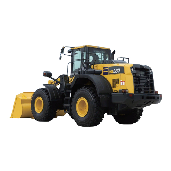
WA380
WHEEL LOADER
SERIAL NUMBERS H65051 AND UP
H15001 AND UP
ORIGINAL INSTRUCTIONS
VENAM48501
-8
Advertisement
Chapters
Table of Contents

Related Manuals for Komatsu WA380-8


Summary of Contents for Komatsu WA380-8
- Page 1 The operator and maintenance personnel must read this manual before commencing operation or maintenance. Keep this manual within reach at all times and ensure that operating personnel read it at regular intervals. © 2016 KOMATSU All Rights Reserved Printed in Europe 10-2016...
- Page 3 Komatsu or Ko- matsu approved rebuilt parts or assemblies or others parts of equivalent quality, and that the engine be serviced by an authorized Komatsu distribu- tor. Failure to follow these recommendations could result in ineffective serv- ice, damage to the product or safety risks (including personal injury or death).
-
Page 4: Eu Directives
Keep it in the storage door (1) beside the shoes box on the left side of the operator's seat. If this manual is lost or damaged, contact Komatsu or your Komatsu distributor and tell them about the machine model name and the serial No. immediately to arrange for its replacement. - Page 5 The transmitter unit must be spatially separated from the vehicle’s electronic system. • Make sure when installing the antenna that this is installed correctly with good earth connection between antenna and vehicle mass. Also observe Komatsu and manufacturer’s installation instructions for wiring, installation and maximum permit- ted power consumption.
-
Page 6: Safety Information
SAFETY INFORMATION FOREWORD SAFETY INFORMATION To enable you to use the machine safely, and to prevent personal injury to operators, service personnel or by- standers, the precautions and warnings included in this manual and the safety signs attached to the machine must always be observed. -
Page 7: Safety Labels
Continuing improvements in the design of this machine can lead to changes in detail which may not be reflected in this manual Consult Komatsu or your Komatsu distributor for the latest available information of your machine or for ques- tions regarding information in this manual. -
Page 8: Introduction
INTRODUCTION FOREWORD INTRODUCTION MAIN USE OF MACHINE This Komatsu machine is designed to be used mainly for the following work: • Digging work • Leveling work • Dozing work • Loading work For details of the work procedure, see “RECOMMENDED APPLICATIONS (3-208)”. -
Page 9: Engine Technology To Conform Exhaust Gas Emission
Catalytic Reduction (SCR) to conform EU Stage IV emission regulation in the European Union. • Komatsu Diesel Particulate Filter (KDPF): A device which captures diesel particular matter or soot in the exhaust gas to purify exhaust gas. If soot is accumulated to a certain level in the filter, a purification process to burn the soot is performed automatically to keep the filtering performance of KDPF high. -
Page 10: Product Information
PRODUCT INFORMATION FOREWORD PRODUCT INFORMATION When requesting service or ordering replacement parts, inform your Komatsu distributor of the following items. LOCATION OF PRODUCT IDENTIFICATION NUMBER (PIN)/MACHINE SERI- AL NO. PLATE This is located at the center of the front frame on the right side of the machine. -
Page 11: Rops/Fops Serial Plate Location
ROPS/FOPS SERIAL PLATE LOCATION AXLE SERIAL PLATE LOCATION This plate is located on the right of front axle and on the left of rear axle. PRODUCED BY KOMATSU GERMANY GmbH, HANNOVER FEDERAL REPUBLIC OF GERMANY FOR Komatsu Ltd.,Tokyo,Japan MODEL PART NO. -
Page 12: Seat Plate Location
It is at the center bottom of the machine monitor. YOUR MACHINE SERIAL NUMBERS AND DISTRIBUTOR Machine serial No. Engine serial No. Product identification number (PIN) Komatsu Germany GmbH Manufacturer name Address Hanomag Strasse 9 30449 Hannover Germany Distributor name... -
Page 13: Declaration Of Conformity
FOREWORD DECLARATION OF CONFORMITY DECLARATION OF CONFORMITY The manufacturer: Komatsu Germany GmbH Hanomag Straße 9 30449 Hannover Germany Declares that this machine: WA380-8* Fulfils all the relevant provisions of following EC Directives: v i t 2004/108/EC until 19 April 2016... -
Page 14: Retrofitting By Third-Party Suppliers
In the event of tools (e.g. loading shovels) being retrofitted by a third-party supplier, the technical specifications of the manufacturer must be taken into account. For this purpose, or for further information, please be sure to consult Komatsu or your local Komatsu dealer. 1-12... -
Page 15: Explanation Of Acronyms
FOREWORD EXPLANATION OF ACRONYMS EXPLANATION OF ACRONYMS Acronyms Stand for: KDPF Komatsu Diesel Particulate Filter KVGT Komatsu Variable Geometry Turbo KCCV Komatsu Closed Crankcase Ventilation Selective Catalytic Reduction Diesel Exhaust Fluid ECSS Electrically Controlled Suspension System 1-13... -
Page 16: Table Of Contents
TABLE OF CONTENTS FOREWORD TABLE OF CONTENTS FOREWORD..............................1-1 BEFORE READING THIS MANUAL ......................1-2 EU DIRECTIVES ..........................1-2 SAFETY INFORMATION .......................... 1-4 SAFETY LABELS ............................. 1-5 INTRODUCTION ............................1-6 MAIN USE OF MACHINE ........................1-6 DIRECTIONS OF MACHINE......................1-6 VISIBILITY FROM OPERATOR'S SEAT .................... - Page 17 OTHER TROUBLE......................... 3-251 MAINTENANCE............................... 4-1 PRECAUTIONS FOR MAINTENANCE ..................... 4-2 CHECK SERVICE METER READING ....................4-2 KOMATSU GENUINE REPLACEMENT PARTS ................4-2 KOMATSU GENUINE LUBRICANTS ....................4-2 ALWAYS USE CLEAN WASHER FLUID .................... 4-2 FRESH AND CLEAN LUBRICANTS ....................4-2 CHECK DRAINED OIL AND USED FILTER..................
- Page 18 EVERY 4500 HOURS MAINTENANCE ................... 4-74 EVERY 8000 HOURS MAINTENANCE ................... 4-74 EVERY 9000 HOURS MAINTENANCE ................... 4-74 SPECIFICATIONS ............................5-1 SPECIFICATIONS ............................ 5-2 SPECIFICATIONS: WA380-8......................5-2 NOISE EMISSION LEVELS ........................5-4 VIBRATION LEVEL........................... 5-5 ATTACHMENTS AND OPTIONS ........................6-1 BUCKET AND TIRE SELECTION......................6-2 HANDLE MULTIFUNCTION MONO-LEVER .....................
- Page 19 TABLE OF CONTENTS RECOMMENDED FUEL, COOLANT, AND LUBRICANT ................7-4 LUBRICATION CHART ........................7-4 METHOD FOR USING FUEL, COOLANT AND LUBRICANTS ACCORDING TO AMBIENT TEMPERA- TURE ............................. 7-6 RECOMMENDED BRANDS AND QUALITIES OTHER THAN KOMATSU GENUINE OILS ....7-7 INDEX................................8-1 1-17...
-
Page 21: Safety
SAFETY Please read and make sure that you fully understand the precautions descri- bed in this manual and the safety labels on the machine. When operating or servicing the machine, always follow these precautions strictly. - Page 22 SAFETY SAFETY SAFETY SAFETY LABELS ............................2-4 LOCATION OF SAFETY LABELS......................2-5 CONTENTS OF SAFETY LABELS ......................2-7 GENERAL PRECAUTIONS COMMON TO OPERATION AND MAINTENANCE ........... 2-15 PRECAUTIONS BEFORE STARTING OPERATION................2-15 ENSURE SAFE OPERATION ......................2-15 UNDERSTAND THE MACHINE ....................... 2-15 PREPARATIONS FOR SAFE OPERATION ....................
- Page 23 SAFETY SAFETY PRECAUTIONS FOR TRANSPORTATION..................... 2-31 PRECAUTIONS WHEN LOADING AND UNLOADING ..............2-31 TOWING AND BEING TOWED....................... 2-32 PRECAUTIONS FOR TOWING AND BEING TOWED..............2-32 PRECAUTIONS FOR MAINTENANCE ......................2-33 PRECAUTIONS BEFORE STARTING INSPECTION AND MAINTENANCE .......... 2-33 DISPLAY WARNING TAG DURING INSPECTION AND MAINTENANCE ........2-33 KEEP WORK PLACE CLEAN AND TIDY ..................
-
Page 24: Safety Labels
If the safety labels are damaged, lost, or cannot be read properly, replace them with new ones. For details of the part numbers for the safety labels, see this manual or the actual label, and place an order to your Komatsu distributor. •... -
Page 25: Location Of Safety Labels
SAFETY SAFETY LABELS LOCATION OF SAFETY LABELS... - Page 26 SAFETY LABELS SAFETY 1. Caution before operating 15. Caution for nearing machine 2. Caution when leaving operator's seat 16. Prohibition of entering beneath work equipment 3. Caution when traveling in reverse 17. Caution for modification of ROPS/FOPS 4. Caution for electric cables 18.
-
Page 27: Contents Of Safety Labels
SAFETY SAFETY LABELS CONTENTS OF SAFETY LABELS Caution before operating “09651-A0481” • Warning! • Read manual before operation, maintenance, disassembly, assembly and transportation. Caution when leaving the operator's seat “09654-C0481” • Sign indicates a hazard of unexpected moving of stopped machine. - Page 28 SAFETY LABELS SAFETY Caution for electric cables “09801-C0481” • Sign indicates an electrocution hazard if machine is brought too near electric power lines. • Keep a safe distance from electric power lines. Prohibition of trespassing “09162-C0641” • Sign indicates a crush hazard between the articulating parts of the vehicle.
- Page 29 SAFETY SAFETY LABELS Caution for emergency release of parking brake “423–93–41370” WARNING If the release valve is set to RELEASE, a serious accident may occur, as this operation releases the parking brake and the machine body may suddenly start to move. Never set the releases valve to RELEASE except when tow- ing the machine in case of machine trouble.
- Page 30 SAFETY LABELS SAFETY Caution for handling battery cable “09808-A1201” • Signal indicates an electric hazard from handling the cable. • Read manual for safe and proper handling. Caution for explosion “09659-A057B” • Signal indicates an explosion. • Never drill, cut, with gas, hit or disassemble. Also keep open flame away.
- Page 31 SAFETY SAFETY LABELS Caution while engine is running “09667-A0481” • Sign indicates a hazard of rotating parts, such as belt. • Turn off before inspection and maintenance. Caution for nearing machine “09806–C0883” • There is danger of being run over by machine. •...
- Page 32 SAFETY LABELS SAFETY Caution for modification of ROPS/FOPS “09620-A2001” “09620-A3001” • If any modification is applied to the ROPS or FOPS, it may affect the strength and may not be comply with the stand- ard. Do not drill, cut, or weld on the ROPS or FOPS struc- ture.
- Page 33 SAFETY SAFETY LABELS Emergency escape “425-93-51110” Caution for blast site (Machines equipped with KOMTRAX) “09845-00480” • Sign indicates an explosion hazard caused by active radio transmitter at a blast zone. • Keep machine at a safe distance from a blast zone and detonator.
- Page 34 SAFETY LABELS SAFETY Caution for handling DEF “09632-61480” • DEF only. To avoid engine damage or fire, fill with DEF on- • Never use diesel fuel. 2-14...
-
Page 35: General Precautions Common To Operation And Maintenance
GENERAL PRECAUTIONS COMMON TO OPERATION AND MAINTE- SAFETY NANCE GENERAL PRECAUTIONS COMMON TO OPERATION AND MAINTENANCE Mistakes in operation, inspection, or maintenance may result in serious personal injury or death. Before per- forming operation, inspection, or maintenance, always read this manual and the safety labels on the machine carefully and obey the warnings. -
Page 36: Precautions For Inside Operator's Compartment
GENERAL PRECAUTIONS COMMON TO OPERATION AND MAINTE- NANCE SAFETY • If water gets into the electrical system, electric devices will cause malfunctions, and the machine will cause error. If the machine cause error, it may move unexpectedly and cause serious personal injury or death. When washing the machine with water or steam, do not allow the water or steam to come into direct contact with electrical compo- nents. -
Page 37: Precautions To Prevent Fire
GENERAL PRECAUTIONS COMMON TO OPERATION AND MAINTE- SAFETY NANCE PRECAUTIONS TO PREVENT FIRE ACTIONS IF FIRE OCCURS • Turn the starting switch to OFF position, and stop the engine. • Use the handrails and steps to escape from the machine. •... -
Page 38: Precautions When Getting On Or Off Machine
Fire around the machine due to highly heated exhaust gas This machine is equipped with Komatsu Diesel Particulate Filter (hereafter KDPF). KDPF is a device to purify the soot in the exhaust gas. Exhaust gas temperature may increase during the purifi- cation process (regeneration). -
Page 39: No Jumping On Or Off Machine
GENERAL PRECAUTIONS COMMON TO OPERATION AND MAINTE- SAFETY NANCE • Do not get on or off the machine with tools in your hand. NO JUMPING ON OR OFF MACHINE Getting on or off the moving machine can cause serious personal injury or death. Always observe the following. •... -
Page 40: Do Not Get Caught In Work Equipment
GENERAL PRECAUTIONS COMMON TO OPERATION AND MAINTE- NANCE SAFETY Whenever leaving the machine, be sure to lower the work equipment to the ground, lock the work equipment by pressing work equipment lock switch (1) (pilot lamp lights up) and stop the engine by setting parking brake switch (2) to ON (opera- tion) position (A). -
Page 41: Precautions Related To Protective Structures
• If the protective structure is damaged or deformed by falling objects or by rolling over, its strength will be reduced and it will not be able to fulfill its function properly. In such cases, always consult your Komatsu distributor. -
Page 42: Precautions For Operation
PRECAUTIONS FOR OPERATION SAFETY PRECAUTIONS FOR OPERATION PRECAUTIONS FOR JOBSITE INVESTIGATE AND CONFIRM JOBSITE CONDITIONS On the jobsite, there are various hidden dangers that may lead to serious personal injury or death. Before start- ing operations, always check the following to confirm that there is no danger on the jobsite. •... -
Page 43: Ensure Good Visibility
SAFETY PRECAUTIONS FOR OPERATION Voltage of Cables Safety Distance 66000 V Min. 4 m 154000 V Min. 5 m 187000 V Min. 6 m 275000 V Min. 7 m 500000 V Min. 11 m • To prepare for any possible emergencies, wear rubber shoes and gloves. Lay a rubber sheet on the opera- tor's seat, and be careful not to touch the chassis with any exposed part of your body. -
Page 44: Start Engine
Always observe the regulations for jobsite and environmental standards. This machine does not contain asbestos, but any part which is not the genuine part, it has risk of containing asbestos. Always use Komatsu genuine parts. START ENGINE USE WARNING TAGS If there is a “DANGER! Do NOT operate!”... -
Page 45: Precautions When Starting Engine
SAFETY PRECAUTIONS FOR OPERATION • Check the coolant level, fuel level, DEF level, and oil level in engine oil pan, check for clogging of the air cleaner, and check for damage to the electric wiring. • Check that there is no mud or dust accumulated around the movable parts of the accelerator pedal or brake pedal, and check that the pedals work properly. -
Page 46: Precautions For Operation
PRECAUTIONS FOR OPERATION SAFETY • Always wear protective eyeglasses and rubber gloves when starting the engine by using the jumper cables. • When connecting a normal machine to a failed machine with the jumper cables, always use the normal machine with the same battery voltage as the failed machine. -
Page 47: Precautions When Traveling
SAFETY PRECAUTIONS FOR OPERATION • Prohibit anyone other than the operator to get on the machine. • If there are any persons in the area around the machine, there is danger that they may be hit or caught by the ma- chine, and this may lead to serious personal injury or death. -
Page 48: Precautions When Traveling On Slopes
PRECAUTIONS FOR OPERATION SAFETY • If you drive the machine at high speed continuously for a long time, the tires will overheat and the internal pressure will become abnormally high. This may cause the tires to burst. If a tire bursts, it produces a large destructive force, and this may cause serious injury or death. -
Page 49: Method Of Using Brakes
SAFETY PRECAUTIONS FOR OPERATION • When the bucket is loaded, direct the bucket toward the hill top both in uphill and downhill travel. When driving the machine with the bucket directing downhill, it is liable to tip over and is dangerous. METHOD OF USING BRAKES •... -
Page 50: Prohibited Operations
PRECAUTIONS FOR OPERATION SAFETY PROHIBITED OPERATIONS If the machine tips over or falls, or the ground at the working point collapses, it may lead to serious personal injury or death. Always observe the following. • Do not dig the work face under an overhangs. There is a danger that the work face will collapse. -
Page 51: Precautions For Transportation
• This machine needs to be divided into components for transportation depending on the regulation. When transporting the machine, consult your Komatsu distributor. • Lock the frame with the frame lock bar to prevent the machine from articulating. -
Page 52: Towing And Being Towed
PRECAUTIONS FOR OPERATION SAFETY • Always use ramps of adequate strength. Be sure that the ramps are wide, long, and thick enough to provide a safe loading slope. Take suitable steps to prevent the ramps from moving out of position or coming off. (1) Chocks (2) Ramp (3) Width of ramps: Same width as tires... -
Page 53: Precautions For Maintenance
SAFETY PRECAUTIONS FOR MAINTENANCE PRECAUTIONS FOR MAINTENANCE PRECAUTIONS BEFORE STARTING INSPECTION AND MAINTENANCE DISPLAY WARNING TAG DURING INSPECTION AND MAINTENANCE During inspection and maintenance, always display the “DAN- GER! Do NOT operate!” warning tag. If there is a “DANGER! Do NOT operate!” warning tag dis- played, it means that someone is performing inspection and maintenance of the machine. -
Page 54: Guards
END OF SERVICE LIFE • For safe dismantling of the machine at the end of service life, please contact your Komatsu distributor. STOP ENGINE BEFORE CARRYING OUT INSPECTION AND MAINTENANCE If you are caught or pinched between the work equipment during operation, or exposed to high-temperature or high-pressure liquids, it is dangerous and may cause serious personal injury or death. -
Page 55: Two Workers For Maintenance When Engine Is Running
When performing maintenance work, perform the after- treatment devices regeneration disable according to “HAN- DLE Komatsu Diesel Particulate Filter (KDPF) (3-133)”. • Lower the work equipment to the ground and press work equipment lock switch (1) to lock the work equipment (pilot lamp lights up) and prevent it from moving. -
Page 56: Turn Off Ecss Switch Before Performing Inspection And Maintenance
PRECAUTIONS FOR MAINTENANCE SAFETY • Set parking brake switch (2) to ON (operation) position (A) to apply the parking brake, then put blocks in front of and behind the tires to prevent the machine from moving. • Do not touch the control levers or steering system. If it is necessary to operate the control lever or steering system, always give a signal to your fellow workers and have them take refuge to a safe place. -
Page 57: Precautions For Check And Maintenance
SAFETY PRECAUTIONS FOR MAINTENANCE • Never use concrete blocks for supports. Concrete blocks may break under even light loads. USE PROPER TOOLS Use the tools suited to the task and use them correctly. Using damaged, deformed, or low quality tools, or making improper use of the tools may cause serious personal injury or death. -
Page 58: Precautions When Using Hammer
PRECAUTIONS FOR MAINTENANCE SAFETY • Do not smoke or bring any open flame close to the battery. • Hydrogen gas is generated when the battery is being charged, so remove the battery from the machine, take it to a well-ventilated place, remove the battery caps, then perform the charging. -
Page 59: Precautions For High-Temperature Coolant
The oil pressure in the ECSS circuit is stored by the accu- mulator. Do not remove the ECSS piping and parts. If it is necessary to remove them, ask your Komatsu dis- tributor to perform the removal work. PRECAUTIONS FOR HIGH-PRESSURE FUEL While the engine is running, high-pressure is generated in the engine fuel piping. -
Page 60: Handle High-Pressure Hoses And Piping
If the hose or piping mounts are loose or oil or fuel is found to be leaking from the mount, stop operations and tighten to the specified torque. If any damaged or deformed hoses or piping are found, consult your Komatsu distributor. Replace the hose if any of the following problems are found. -
Page 61: Precautions For Disposing Of Waste Materials
SAFETY PRECAUTIONS FOR MAINTENANCE If any doubt exists, contact your Komatsu distributor. PRECAUTIONS FOR DISPOSING OF WASTE MATERIALS To prevent pollution, pay full attention to the way to dispose of waste materials. • Always drain the oil from your machine in containers. Nev- er drain the oil and coolant directly onto the ground or dump into the sewage system, rivers, seas, or lakes. -
Page 62: Tires
To ensure safety, always observe the following. • Maintenance, disassembly, repair, and assembly of the tires and rims requires special equipment and special tech- nology, so always ask your Komatsu distributor to perform these operations. • Use only specified tires and inflate them to the specified pressure. -
Page 63: Precautions For Def
SAFETY PRECAUTIONS FOR DEF PRECAUTIONS FOR DEF GENERAL CHARACTER AND PRECAUTIONS FOR HANDLING DEF is a colorless transparent 32.5% aqueous urea solution. Urea as main constituent is a material which is used for cosmetics, medical and pharmaceutical products, and fertilizer, etc. The following situations require im- mediate action: •... -
Page 65: Operation
OPERATION Please read and make sure that you understand the SAFETY section before reading this section. -
Page 66: General View
GENERAL VIEW OPERATION GENERAL VIEW MACHINE EQUIPMENT NAME (1) Bucket (8) Rear wheel (2) Bell crank (9) Stepladder (3) Bucket cylinder (10) L.H. side under-mirror (4) R.H. side under-mirror (11) Turn signal lamp (5) Rearview mirror (12) Headlamp (6) Front working lamp (13) Lift cylinder (7) ROPS cab (14) Front wheel... -
Page 67: Controls And Gauges Names
OPERATION GENERAL VIEW (15) Boom (18) Rear combination lamp (16) Rear working lamp (19) Auto-greasing (17) Rearview camera (20) Chock (if equipped) CONTROLS AND GAUGES NAMES (1) Front switch panel (14) Rear view monitor (2) Directional lever (15) Bucket control lever (3) Engine shutdown secondary switch (16) Kickdown switch (4) Hazard lamp switch... - Page 68 GENERAL VIEW OPERATION SWITCH PANEL g0038110 R.H. switch panel (1) Transmission cut-off switch (5) Directional selector enable switch on R.H. switch panel (if equipped) (1) Transmission cut-off set switch (6) Remote positioner switch (2) Power mode selector switch (7) Auto-digging switch (3) Transmission shift mode selector switch (8) Secondary steering switch (4) Torque converter lockup switch...
- Page 69 OPERATION GENERAL VIEW MACHINE MONITOR EQUIPMENT NAME General view (A) LCD unit (C) Meter unit (B) LED unit (1) Torque converter oil temperature gauge (16) Speedometer (2) Torque converter oil temperature caution lamp (17) Hydraulic oil temperature caution lamp (3) Engine coolant temperature caution lamp (18) Hydraulic oil temperature gauge (4) Engine coolant temperature gauge (19) Fuel level caution lamp...
- Page 70 GENERAL VIEW OPERATION Display of liquid crystal unit (A) Standard screen (D) Warning screen (B) ECO guidance screen (E) User menu screen (C) Maintenance time warning screen (28) Message display (40) Preheating pilot lamp (29) Auto-digging pilot lamp (40) Transmission cut-off pilot lamp (30) Auto-greasing pilot lamp (41) Fan reverse display (31) Directional selection pilot lamp (if equipped)
-
Page 71: Other Equipment Name
OPERATION GENERAL VIEW *ECSS: Electronically Controlled Suspension System * At sections (36) and (40), 2 types of pilot lamp are prepared. OTHER EQUIPMENT NAME Inside of cab (1) 24 V power supply (8) Open lock for cab L.H. door (2) Rearview monitor (9) Cab door handle (3) Ashtray (10) Fuse... - Page 72 GENERAL VIEW OPERATION Outside of cab (1) Slow-blow fuse (3) Articulation lock pin (2) Dust indicator (4) Toolbox (if equipped)
- Page 73 OPERATION GENERAL VIEW (5) KDPF (10) System operating lamp (6) DEF injector (11) DEF pump (7) SCR assembly (12) DEF filter (8) Komatsu Closed Crankcase Ventilation (hereafter (13) DEF tank KCCV) ventilator (9) Battery disconnect switch...
-
Page 74: Explanation Of Components
EXPLANATION OF COMPONENTS OPERATION EXPLANATION OF COMPONENTS The following is an explanation of devices necessary to operate the machine. To perform suitable operations correctly and safely, it is important to completely understand methods of operat- ing the equipment, and the meanings of the displays. EXPLANATION OF MACHINE MONITOR EQUIPMENT FF: Failure display screen (A) Warning display... - Page 75 NOTICE If the lamps, alarm buzzer, etc. do not work, the machine monitor may be failed or the electric wiring may have breakage. In this case, ask your Komatsu distributor for repair. REMARK When the engine is started, the battery voltage may suddenly drop depending on the temperature and the bat- tery condition.
- Page 76 5 seconds, and then screen goes out. End screen with message If there is any message from your Komatsu distributor, it is displayed on end screen DD for 5 seconds, and then the screen goes out. In this case, turn the starting switch to ON position to re-check the message, and if it is the message requesting response, send back your reply.
- Page 77 Starting screen BB without inputting ID number. REMARK • Contact your Komatsu distributor for details of the method of setting, changing, or canceling the operator identification function. • Depending on the set value of ID holding time, even if inputting ID number for operator identification func- tion is set, the ID number input screen LL (with SKIP) or MM (without SKIP) may not be displayed while the starting switch is turned to ON position.
- Page 78 Be careful not to use it for the purpose of security enhance- ment. Komatsu cannot accept any responsibility for any loss or damage resulting from the wrong use of ID or unauthorized use of ID by a third person.
- Page 79 OPERATION EXPLANATION OF COMPONENTS BASIC OPERATION OF MACHINE MONITOR WHEN TROUBLE OCCURS WHILE OPERATING MACHINE If any trouble occurs during operation, the standard screen BB changes to the failure display screen FF. When ENTER switch is pressed while guidance icon (1) is dis- played, the “Current Abnormality”...
- Page 80 EXPLANATION OF COMPONENTS OPERATION (1) Torque converter oil temperature caution lamp (7) Seat belt caution lamp (2) Engine coolant temperature caution lamp (8) Action level (3) Warning display (9) Brake oil pressure caution lamp (4) Warning display (10) Hydraulic oil temperature caution lamp (5) Centralized warning lamp (11) Fuel level caution lamp (6) Guidance icon...
- Page 81 Stop the operation and move the machine to a safe Sounds in- Lights up Lights up place, then ask your Komatsu distributor for inspec- termittently in red tion and maintenance. High If there is an overrun related display, reduce the en- gine speed and machine travel speed while continu- ↑...
- Page 82 (A) Caution lamp (B) Action level (C) Failure code Code to indicate the content of the failure. Notify it when calling your Komatsu distributor. (D) Failure name (E) Message Take appropriate remedies according to the displayed message. (F) Contact telephone number The telephone number of the contact such as your Komatsu distributor is displayed.
- Page 83 OPERATION EXPLANATION OF COMPONENTS (G) Guidance icon On the “Current Abnormality” list screen, the following switches displayed in guidance icon (G) can be operated. UP switch: Moves to the previous page. When on the first page, it moves to the last page. DOWN switch: Moves to the next page.
- Page 84 Stop the operation, move the machine to a safe place, stop the engine, then ask your Komatsu distributor for in- spection and maintenance. • When action level is not displayed and lamp lights up in If the brake oil pressure is below the specified value while the engine is stopped, the lamp lights up in red.
- Page 85 The caution lamp lights up in yellow. When you finish the operation, always perform the inspection and maintenance. Ask your Komatsu distributor for the inspection and maintenance as needed. WORK EQUIPMENT SYSTEM CAUTION LAMP The work equipment system caution lamp warns about abnor- mality in the work equipment system.
- Page 86 If the brake oil temperature caution lamp frequently lights up, record the operation, travel speed, and the state of braking just before the lamp lights up, then consult your Komatsu distributor. DEF LEVEL CAUTION LAMP DEF level caution lamp alerts when DEF tank level becomes low.
- Page 87 This lamp warns about the abnormality related to the auto- greasing. If the lamp lights up in red, stop the work immediately and ask your Komatsu distributor for inspection and maintenance. GREASE LEVEL OF AUTO-GREASING SYSTEM CAUTION LAMP This lamp warns about low level of remaining grease in the grease pump.
- Page 88 Komatsu distributor for in- spection and maintenance. • When action level “L01” is displayed The lamp lights up in yellow. When you finish the operation, always perform the inspection and maintenance. Ask your Komatsu distributor for the inspection and maintenance as needed. 3-24...
- Page 89 The caution lamp lights up in red. At the same time, the centralized warning lamp lights up and alarm buzzer sounds intermittently. Stop the operation, move the machine to a safe place, stop the engine, then ask your Komatsu distributor for inspection and maintenance.
- Page 90 After the operation is finished, move the machine to a safe place and perform manual stationary regenera- tion. REMARK For details of the manual stationary regeneration, see “HANDLE Komatsu Diesel Particulate Filter (KDPF) (3-133)”. DEF SYSTEM CAUTION LAMP DEF system caution lamp alerts when abnormality in the sys- tem are detected.
- Page 91 The lamp lights up in red. At the same time, the centralized warning lamp lights up and alarm buzzer sounds intermit- tently. Stop the operation, move the machine to a safe place, stop the engine, then ask your Komatsu distributor for inspection and maintenance. •...
- Page 92 See “METHOD FOR CHECKING COOLANT LEVEL, ADDING COOLANT (3-163)”. If it occurs again in a short time, the coolant may be leaking from the radiator. Ask your Komatsu distributor for inspection and maintenance. CHARGE LEVEL CAUTION LAMP Charge level caution lamp warns about abnormality in the charging system while the engine is running.
- Page 93 The lamp lights up in yellow. When you finish the operation, always perform the inspection and maintenance. Ask your Komatsu distributor for the inspection and maintenance as needed. AIR CONDITIONER SYSTEM CAUTION LAMP Air conditioner system caution lamp warns about abnormality in air conditioner system.
- Page 94 • By default, the maintenance time caution lamp (yellow) is set to light up when the remaining time reaches 30 hours. However, you can change this setting. To change the setting, ask your Komatsu distributor. CENTRALIZED WARNING LAMP The centralized warning lamp lights up in red and at the same time the alarm buzzer sounds intermittently when the machine is in any of the following conditions.
- Page 95 OPERATION EXPLANATION OF COMPONENTS Machine conditions under which centralized warn- Other monitor displays ing lamp lights up When starting switch is turned to ON position while The current gear speed flashes. the directional lever or directional selector switch (if equipped) is not in NEUTRAL position (N) . When all signals from directional lever or direction- al selector switch (if equipped) are turned OFF.
- Page 96 EXPLANATION OF COMPONENTS OPERATION When the starting switch is ON, the pilot lamps light up when the display items are functioning. (1) Message display (14) Remote positioner display (2) Auto-digging pilot lamp (15) Shift lever position display (3) Auto-greasing pilot lamp (16) Automatic shift pilot lamp (4) Directional selection pilot lamp (if equipped) (17) Torque converter lockup mode display...
- Page 97 OPERATION EXPLANATION OF COMPONENTS Pop up display For some pilot lamps, pop-up (a) is displayed on the screen when they are selected. See the details of the pilot lamps shown below. TURN SIGNAL PILOT LAMP The turn signal pilot lamp flashes synchronously with the turn signal lamp, when it is turned on.
- Page 98 EXPLANATION OF COMPONENTS OPERATION AUTO-DIGGING PILOT LAMP The auto-digging pilot lamp lights up while the auto-digging system is working. AUTO-GREASING PILOT LAMP The auto-greasing pilot lamp lights up while the auto-greasing system is working. DIRECTIONAL SELECTION PILOT LAMP (if equipped) The directional selection pilot lamp lights up in green when the directional selector enable switch on R.H.
- Page 99 OPERATION EXPLANATION OF COMPONENTS 2-STAGE LOW IDLING PILOT LAMP The 2-stage low idling pilot lamp lights up when the 2-stage low idling is effective. At a place of high altitude and such, the 2-stage low idling be- comes effective automatically, and the pilot lamp lights up. The pilot lamp lights up when the 2-stage low idling is set to ON as well.
- Page 100 EXPLANATION OF COMPONENTS OPERATION TORQUE CONVERTER LOCKUP MODE DISPLAY The torque converter lockup pilot lamp displays the set state of the torque converter lockup mode. By selecting torque converter lockup mode selector switch, one of the following lamps lights up. (A): Lockup mode ON (B): Lockup mode OFF When the mode is changed, the display pops up.
- Page 101 For detail, see “HANDLE AIR CONDITIONER (3-224)”. MESSAGE DISPLAY The message display lights up when there is a message from Komatsu. (A): There is unread message (B): There is any read message to which no reply is made. To read the message, see “MESSAGE DISPLAY (3-91)”.
- Page 102 Also, keep combustible materials away from the exhaust pipe outlet to prevent a fire. • If there is a thatched roof, dead leaves, paper, or other combustible matter near the machine, see “HANDLE Komatsu Diesel Particulate Filter (KDPF) (3-133)”. Aftertreatment devices regeneration display indicates the re- generation state of the aftertreatment devices.
- Page 103 OPERATION EXPLANATION OF COMPONENTS SHIFT INDICATOR The shift indicator shows the transmission shift range (gear speed). SHIFT LEVER POSITION DISPLAY The shift lever position display shows the position of the direc- tional lever or directional selector switch (if equipped) in en- larged letters.
- Page 104 EXPLANATION OF COMPONENTS OPERATION REMARK Display/Non-display of ECO guidance can be switched. For the method of switching the display, see “SWITCH DISPLAY/NON-DISPLAY OF ECO GUIDANCE (3-60)”. EXCESSIVE IDLING GUIDANCE If the engine continues running idle for more than 5 minutes, the excessive idling message is displayed on the monitor.
- Page 105 OPERATION EXPLANATION OF COMPONENTS GUIDANCE TO RECOMMEND SHIFTING UP GEAR TO 4TH If the machine travels at a speed of 20.4 km/h or higher and at accelerator opening of 80 % or more for 30 seconds with the gear speed switch set in the 3rd position, the notification of rec- ommendation to shift up the gear to the 4th is displayed on the monitor.
- Page 106 EXPLANATION OF COMPONENTS OPERATION When the time until engine output power limitation starts is 1 to 8 hours “Approx. * hours remaining to DEF refill caution.” is displayed. When the time until engine output power limitation starts is less than 1 hour “DEF refill caution will appear soon.”...
- Page 107 OPERATION EXPLANATION OF COMPONENTS (7) DEF level gauge (9) R.H. meter (8) Fuel gauge (10) L.H. meter SPEEDOMETER The speedometer indicates the travel speed of the machine. ENGINE TACHOMETER The engine tachometer indicates the engine speed. If the engine speed is higher than the allowable range during operation, the engine overrun caution lamp lights up in red.
- Page 108 EXPLANATION OF COMPONENTS OPERATION Stop the machine in a safe place, set the directional lever and directional selector switch (if equipped) to NEU- TRAL position (N), and run the engine at a medium speed with no load until the torque converter oil temperature caution lamp goes out.
- Page 109 OPERATION EXPLANATION OF COMPONENTS • Clock For the method of selecting the display, see “SELECT L.H. METER DISPLAY (3-80)”. The R.H. meter indicates either of the following which can be selected. • Fuel consumption gauge • Service meter • Odometer •...
- Page 110 EXPLANATION OF COMPONENTS OPERATION Fuel consumption gauge display Indicates the average fuel consumption of the machine. (C): Average fuel consumption in a day (D): Split fuel consumption (under measuring) (E): Split fuel consumption (when measuring is stopped) REMARK Display on the fuel consumption gauge can be switched be- tween the average fuel consumption per day (from 0:00 am of the day to 0:00 am of the next day) and the average fuel con- sumption during an selected period (split fuel consumption).
- Page 111 OPERATION EXPLANATION OF COMPONENTS The function of each switch varies depending on the screen of the machine monitor. (1) UP switch (5) RETURN switch (2) Air conditioner switches, numeric keypad (6) DOWN switch (3) Menu switch (7) Guidance icon (4) ENTER switch MENU SWITCH When this switch is pressed on the standard screen, the follow- ing user menu screen is displayed.
- Page 112 EXPLANATION OF COMPONENTS OPERATION RETURN SWITCH Pressing RETURN switch cancels a selection or changes, and returns the screen to the previous screen or the standard screen. UP SWITCH Pressing UP switch moves the cursor up by one item. When on the first line, it moves to the last line.
- Page 113 OPERATION EXPLANATION OF COMPONENTS REMARK The switches effective on each screen can be checked with the guidance icon. This function is not available when you press a switch not marked by the guidance icon or you press the guidance icon it- self.
- Page 114 EXPLANATION OF COMPONENTS OPERATION The user menu consists of the following kinds. The menu screen can be changed by pressing the menu switch (1). (A): “Energy Saving Guidance” (B): “Machine Setting and Information” (C): “Aftertreatment Devices Regeneration” (D): “SCR Information” (E): “Maintenance”...
- Page 115 OPERATION EXPLANATION OF COMPONENTS (D) “SCR Information” • Check of DEF level • Information on DEF system (E) “Maintenance” • Check and reset of various maintenance remaining times (F) “Monitor Setting” • “Rearview Monitor Setting” • “Meter Display Selection” • “Screen Adjustment”...
- Page 116 EXPLANATION OF COMPONENTS OPERATION (4) RETURN switch Cancels a selection or changes, and returns to the previous screen or the standard screen. REMARK • If no switch is operated for 30 seconds on the user menu screen, the screen automatically returns to the previous screen or the standard screen.
- Page 117 OPERATION EXPLANATION OF COMPONENTS REMARK For the definition and display change method of “1 Day” and “Split Time”, see “SET DISPLAY OF FUEL CON- SUMPTION GAUGE (3-57)”. When “Average Fuel Consumption Display” is set to “1 Day” “1 Day” is displayed on the place shown with arrow in the right figure.
- Page 118 EXPLANATION OF COMPONENTS OPERATION ECO GUIDANCE RECORD On “ECO Guidance Records” screen, the frequency of display of the ECO guidance on a daily basis or during the split meas- urement period and “Operational Advice” are displayed. Select ECO Guidance Records from Energy Saving Guidance menu screen, then press ENTER switch (1).
- Page 119 OPERATION EXPLANATION OF COMPONENTS When display of “Average Fuel Consumption Display” is set to “Split Time”, and split time measurement is stopped (C) Display while measurement is stopped (D) Dates and times when the measurement is started and stopped To start the split time measurement, see the guidance icon and press ENTER switch (1).
- Page 120 EXPLANATION OF COMPONENTS OPERATION • When display of the “Last 12 hours” is selected • When display of the “Last 7 days” is selected REMARK The graph of the “Last 12 hours” is updated every hour of the service meter reading. The graph of the “Last 7 days”...
- Page 121 OPERATION EXPLANATION OF COMPONENTS DISPLAY SETTING On the “Configurations” menu, it is possible to perform follow- ing settings. • Setting “Average Fuel Consumption Display” • Switching ON/OFF of “ECO Gauge Display” • Setting “ECO Gauge Display Fuel Target Value” • Switching ON/OFF of ECO guidance •...
- Page 122 EXPLANATION OF COMPONENTS OPERATION Select “1 Day” or “Split Time”, then press ENTER switch (1). The default is “1 Day”. To cancel, press RETURN switch (2). “1 Day” Displays the average fuel consumption in 1 day from 0:00 a.m. of the day to 0:00 a.m. of the next day. Reset at 0.00 a.m.
- Page 123 OPERATION EXPLANATION OF COMPONENTS Select “ON” or “OFF”, then press ENTER switch (1). “ON” Displays the ECO gauge. “OFF” Does not display the ECO gauge. To cancel, press RETURN switch (2). The default is “ON”. REMARK For the ECO gauge, see “ECO GAUGE (3-44)”. If the “ECO Gauge Display”...
- Page 124 EXPLANATION OF COMPONENTS OPERATION Using UP switch (2) or DOWN switch (3) to set the value, and press ENTER switch (1). (2) UP switch Increases the target fuel consumption value by 1 ℓ/h. (3) DOWN switch Decreases the target fuel consumption value by 1 ℓ/h. To cancel, press RETURN switch (4).
- Page 125 OPERATION EXPLANATION OF COMPONENTS Select “ON” or “OFF”, then press ENTER switch (1). “ON” Displays the ECO guidance. “OFF” Does not display the ECO guidance. To cancel, press RETURN switch (2). The default is “ON”. REMARK • For the ECO guidance, see “ECO GUIDANCE (3-39)”. •...
- Page 126 EXPLANATION OF COMPONENTS OPERATION Select “ON” or “OFF”, then press ENTER switch (1). “ON” Displays the operational advice on the end screen. “OFF” Does not display the operational advice on the end screen. To cancel, press RETURN switch (2). The default is “ON”. REMARK In the “Operational Advice”...
- Page 127 OPERATION EXPLANATION OF COMPONENTS Select “E light Mode / E Mode Selection” on “Machine Set- ting and Information” menu, and press ENTER switch (1). Select the mode, then press ENTER switch (1). • “E light Mode” • “E Mode” The default is “E light Mode”. RADIATOR FAN MANUAL REVERSE MODE CAUTION When rotating the fan in the reverse direction, beware extremely that dirt will not fly out and cloth, etc.
- Page 128 EXPLANATION OF COMPONENTS OPERATION Select “Manual Fan Reverse Mode” on the “Machine Set- ting and Information”, and press ENTER switch. REMARK The fan rotation switches from the normal direction to the reverse direction only when all of the following conditions are met.
- Page 129 OPERATION EXPLANATION OF COMPONENTS If the condition for reversing the fan is not satisfied, changeover condition waiting pilot lamp (4) lights up in red. Set the engine speed to high idle and perform cleaning. After finishing cleaning, set the engine speed to low idle. If the menu switch is pressed on the standard screen, the screen shown in the figure is displayed.
- Page 130 Initially, “Mode A” is selected. When you want other than above settings for the duration and cycle of the fan reverse rotation, consult your Komatsu distributor. REMARK The fan rotation switches from the normal direction to the reverse direction only when all of the following conditions are met.
- Page 131 OPERATION EXPLANATION OF COMPONENTS When the set changeover time elapses, fan reverse pilot lamp (2) flashes and lights up. If the condition for reversing the fan is not satisfied, changeover condition waiting pilot lamp (3) lights up in red. The fan returns from the reverse rotation to the normal when the set duration for the reverse rotation elapses.
- Page 132 EXPLANATION OF COMPONENTS OPERATION Select “2-Stage Low Idle Setting” on “Machine Setting and Information” menu, and press ENTER switch (1). Select “ON” or “OFF”, then press ENTER switch (1). “ON” The 2-stage low idling operates, and the low idle speed in- creases.
- Page 133 OPERATION EXPLANATION OF COMPONENTS Select “Bucket Level Position Selection” on “Machine Set- ting and Information” menu, then press ENTER switch (1). “Bucket Level Position Selection” allows the settings for 3 types of bucket A to C. “Bucket Level Position Adjustment” When using a newly delivered machine or installing another bucket to a currently used machine, you must adjust the level position of the bucket.
- Page 134 EXPLANATION OF COMPONENTS OPERATION According to the screen instructions, set the bucket hori- zontal, lower the boom to the ground and press ENTER switch. The screen switches to STEP2. According to the screen instructions, raise the boom to the highest position. When this operation ends successfully, the bucket level position is adjusted as intended.
- Page 135 OPERATION EXPLANATION OF COMPONENTS AUTO KICK DOWN SETTING When the shift mode is set to the digging mode automatically, auto-kickdown shifts the gear speed to 1st automatically and eliminates operator's operation. Select “Auto Kick Down Setting” on “Machine Setting and Information”...
- Page 136 EXPLANATION OF COMPONENTS OPERATION Press ENTER switch (1) to reset or press RETURN switch (2) to cancel resetting. AUTO IDLE STOP TIMER SETTING Stops the engine automatically when the idle state continued for a predetermined time. The auto idle stop works only when all of the following conditions are met. •...
- Page 137 OPERATION EXPLANATION OF COMPONENTS Select the operating time of the auto idle stop, and press ENTER switch (1). REMARK Selecting “OFF” disables operation of the auto idle stop. If the idle state is continued up to 30 seconds before the current auto idle stop timer setting , the countdown screen is displayed on the standard screen.
- Page 138 For details of the aftertreatment devices regeneration, see “HANDLE Komatsu Diesel Particulate Filter (KDPF) (3-133)”. The operation methods and the contents of the display of KDPF regeneration and urea SCR regeneration are common.
- Page 139 OPERATION EXPLANATION OF COMPONENTS SCR INFORMATION Each item in “SCR Information” menu (D) is for displaying infor- mation related to SCR and DEF. For details of “SCR Information”, see “HANDLE UREA SCR SYSTEM WARNING (3-142)”. MAINTENANCE SCREEN SETTING Each item on “Maintenance” menu screen (E) is used for dis- playing and setting the notification relevant to maintenance.
- Page 140 “Coolant Change” are not set initially. If you want to change the setting for the maintenance interval and the maintenance notice time, consult your Komatsu distrib- utor. When the maintenance time caution lamp (2) is lit on the stand- ard screen, press the menu switch, and the screen automati- cally displays the “Maintenance”...
- Page 141 Input the password for restriction of use by using the nu- meric keypad, then press ENTER switch (1). REMARK For the setting, changing, or canceling the password, ask your Komatsu distributor. The screen changes to Maintenance Due Time Reset screen. When ENTER switch (1) is pressed, the following reconfir- mation screen is displayed.
- Page 142 EXPLANATION OF COMPONENTS OPERATION Select “Rearview Monitor Setting” on the “Monitor Setting” menu screen, and press ENTER switch (1). Reference line display The is used to change ON/OFF of the reference line on the rearview monitor. Select “Guide Line Display Mode” from the “Rearview Monitor Setting”...
- Page 143 OPERATION EXPLANATION OF COMPONENTS Select “Reverse-interlock Selection mode” on the “Rear- view Monitor Setting” menu, then press ENTER switch (1). Select “ON” or “OFF”, then press ENTER switch (1). “ON” Displays images on the rear view monitor only when trav- eling in reverse.
- Page 144 EXPLANATION OF COMPONENTS OPERATION Select “Meter Display Selection” on the “Monitor Setting” menu screen, then press ENTER switch (1). SELECT L.H. METER DISPLAY This is used for the selection of the items to be displayed on the L.H. meter display. Select “LH Meter Display Selection”...
- Page 145 OPERATION EXPLANATION OF COMPONENTS REMARK For details of each item, see “L.H. AND R.H. METER (3-44)”. The default of L.H. meter is “SMR: Service Meter”. SELECT R.H. METER DISPLAY This is used for the selection of the items to be indicated on the R.H. meter display. Select “RH Meter Display Selection”...
- Page 146 EXPLANATION OF COMPONENTS OPERATION Adjust the brightness by using the switch panel. The brightness can be adjusted individually in the day and night modes. (1) Menu switch Brightness is set to default. (2) UP switch Brightness increases. (Moves the indicator to the right by one division.) (3) DOWN switch Brightness decreases.
- Page 147 OPERATION EXPLANATION OF COMPONENTS Select “GPS Synchronization” from the “Clock Adjustment” menu, then press ENTER switch (1). Select “ON” or “OFF”, then press ENTER switch (1). “ON” Sets the date and time automatically. “OFF” Does not set the date and time automatically. (Can be set manually.) REMARK This setting is held even if the starting switch is turned to OFF...
- Page 148 EXPLANATION OF COMPONENTS OPERATION Select “Calendar” from the “Clock Adjustment” menu, then press ENTER switch (4). REMARK As long as “ON” is selected for the “GPS Synchronization”, “Calendar” is not selectable. The “Calendar” screen is displayed. When year display (A) is highlighted in yellow, operate the switches as follows to change year display.
- Page 149 OPERATION EXPLANATION OF COMPONENTS When day display (C) is highlighted in yellow, operate the switches as follows to change day display. When it is not necessary to change the day setting, press ENTER switch (4). (1) UP switch Advances calendar one day. (2) DOWN switch Puts calendar back one day.
- Page 150 EXPLANATION OF COMPONENTS OPERATION When minute display (E) is highlighted in yellow, operate the switches as follows to change minute display. When it is not necessary to change the minute setting, press ENTER switch (4). (1) UP switch Advances time one minute. (2) DOWN switch Puts time back one minute.
- Page 151 OPERATION EXPLANATION OF COMPONENTS Select “Daylight Saving Time” from the “Clock Adjustment” menu, then press ENTER switch (1). Select “ON” or “OFF”, then press ENTER switch (1). “ON” Displays the time 1 hour forward. “OFF” Returns the time to the original. REMARK Daylight saving time or summer time means moving the clock forward an hour to take advantage of the fact that the sun rises...
- Page 152 The “Operator ID” menu is not displayed when the operator identification function is disabled. REMARK Contact your Komatsu distributor for details of the method of setting, changing, or canceling the operator identi- fication function. WHEN OPERATOR IDENTIFICATION FUNCTION IS AVAILABLE WITH SKIP When the starting switch is ON and ID is inputted, the identified ID is displayed in the column of “Operator ID”...
- Page 153 OPERATION EXPLANATION OF COMPONENTS When the starting switch is ON and “SKIP” is selected, “****” is displayed in the column of “Operator ID” on the “Monitor Set- ting” menu screen. Select “Operator ID” on the “Monitor Setting” menu screen, then ENTER switch (1) for 1 second. The “Operator ID Change”...
- Page 154 EXPLANATION OF COMPONENTS OPERATION • When you press menu switch (2) on the “Operator ID Change” screen, a message is displayed below and the screen returns to the “Monitor Setting” menu screen. On the “Monitor Setting” menu screen, as the same way when the starting switch is ON and “SKIP”...
- Page 155 In this case, the identified ID is not changed. MESSAGE DISPLAY On machines equipped with KOMTRAX, you can see the mes- sages from your Komatsu distributor on this User Message menu (G). When there is any message, message display (1) of the stand- ard screen lights up.
- Page 156 EXPLANATION OF COMPONENTS OPERATION REMARK • While message display (1) is lit on the standard screen, when menu switch (2) is pressed, User Message menu screen (G) is displayed automatically. • When the starting switch is turned OFF while there is any unread message, the message is displayed on the end screen, and when the monitor is started next time, the message changes to a read message.
- Page 157 NOTICE If the monitor screen is displayed during other operations while the starting switch is at OFF position, there is proba- bly a failure in the equipment, so ask your Komatsu dis- tributor for inspection. 3-93...
-
Page 158: Switches
EXPLANATION OF COMPONENTS OPERATION SWITCHES g0038111 (1) ECSS switch (2) Front working lamp switch 3-94... - Page 159 OPERATION EXPLANATION OF COMPONENTS (3) Engine shutdown secondary switch (18) Beacon lamp switch (if equipped) (4) Gear speed switch (19) Auto-greasing switch (5) Hazard lamp switch (20) Rear working lamp switch (6) Horn switch (21) Rear heated wire glass switch (7) Lamp switch (22) Room lamp switch (7) Turn signal lever...
- Page 160 EXPLANATION OF COMPONENTS OPERATION CIGARETTE LIGHTER The cigarette lighter is used to light cigarettes. When the cigarette lighter is pushed in, it will return to its origi- nal position after a few seconds, so pull it out to use it. If the cigarette lighter is removed, the socket can be used as an 85 W (24 V x 3.5 A) power supply.
- Page 161 OPERATION EXPLANATION OF COMPONENTS HORN SWITCH If you press the horn switch, the horn sounds. KICKDOWN SWITCH The kickdown switch is located at the top of the boom control lever. In the manual shift mode, each time the kickdown switch is pressed while the machine is traveling in forward 2nd (F2) , the gear speed is shiftted down to forward 1st (F1).
- Page 162 EXPLANATION OF COMPONENTS OPERATION REMARK • To cancel the kickdown, operate the directional lever. In the manual shift mode, the kickdown can also be canceled by setting the gear speed switch to a position other than the 2nd. • When the starting switch is turned to OFF position and then to ON position again while the gear speed is kicked down, the kickdown is canceled.
- Page 163 If the parking brake was used as a secondary brake when the machine was traveling at high speed, ask your Komatsu distributor for inspection of the parking brake system. The parking brake switch is used to apply the parking brake.
- Page 164 EXPLANATION OF COMPONENTS OPERATION HOLD SWITCH When HOLD switch on the side face of the boom control lever knob is pressed to fix the gear speed in the auto-shift mode, the transmission is fixed to the gear speed indicated on shift in- dicator (A) of the machine monitor and shift hold pilot lamp (B) lights up.
- Page 165 OPERATION EXPLANATION OF COMPONENTS The room lamp switch illuminates the room lamp. Position (A): OFF (goes out) Position (B): Lights up when cab door opens. Position (C): ON (lights up) REMARK • The room lamp lights up even when the starting switch is at OFF position.
- Page 166 EXPLANATION OF COMPONENTS OPERATION NOTICE • Before operating the ECSS switch, be sure to stop the machine and lower the work equipment to the ground. • When performing inspection or maintenance, lower the work equipment to the ground first, press ECSS switch to OFF position, then start the work.
- Page 167 OPERATION EXPLANATION OF COMPONENTS Use the hazard lamp switch when you need to park the ma- chine on a road due to machine failure or during emergency only. Position (A): The turn signal lamps and the turn signal pilot lamp flash. Position (B):The lamps go out.
- Page 168 Even if the engine was stopped while P mode had been set, the mode becomes E light mode/E mode when the engine is started next. If you want to make any change to the setting at the engine start, consult your Komatsu distributor. 3-104...
- Page 169 OPERATION EXPLANATION OF COMPONENTS TRANSMISSION SHIFT MODE SELECTOR SWITCH The transmission shift mode selector switch is used to switch the transmission between the auto shift and manual, and also change the shift point when the auto shift is selected. When this switch is at (B) or (C) position, the transmission is set in the auto shift mode and the auto shift pilot lamp lights up on the machine monitor.
- Page 170 EXPLANATION OF COMPONENTS OPERATION REMOTE POSITIONER SWITCH The remote positioner switch is used to freely set the stopping position of the boom and bucket. If you release your hand from the switch, it automatically re- turns to its original position. Position (A): Sets or cancels stopping position of boom Position (B): Sets or cancels stopping position of bucket For the setting and canceling method of the remote positioner,...
- Page 171 OPERATION EXPLANATION OF COMPONENTS REAR HEATED WIRE GLASS SWITCH When pressing the switch for rear window glass with heated wire, the rear heated wire glass is turned ON to clear the glass. Position (A): ON (Clearing the glass) Position (B): OFF WORK EQUIPMENT LOCK SWITCH WARNING •...
- Page 172 EXPLANATION OF COMPONENTS OPERATION MANUAL SHIFT A desired gear speed can be selected from the 4 forward and 4 reverse gear speeds by turning the gear speed switch to that gear speed position. Use the 1st and 2nd gear speeds for work and the 3rd and 4th for travel.
- Page 173 OFF position but the engine does not stop. • Use the engine shutdown secondary switch only in an emergency. Contact your Komatsu distributor for repair immediately when there is any abnormality on this switch. • If the engine shutdown secondary switch is set to STOP ENGINE position by mistake while the ma- chine is operating normally, “Engine Shutdown Secondary SW in Operation”...
- Page 174 EXPLANATION OF COMPONENTS OPERATION Pull up the switch, and the engine stops. (a) STOP ENGINE: When abnormal (switch is set up) (b) NORMAL: When normal (switch is set down) • When cover (1) is closed, the engine shutdown secon- dary switch automatically returns to NORMAL position (b).
-
Page 175: Control Levers And Pedals
OPERATION EXPLANATION OF COMPONENTS CONTROL LEVERS AND PEDALS (1) Steering tilt lock lever (4) Boom control lever (2) Directional lever (5) Accelerator pedal (3) Bucket control lever (6) Brake pedal DIRECTIONAL LEVER The directional lever switches the machine travel between the forward and reverse. - Page 176 0 to 162 mm NOTICE Do not operate the steering tilt lock lever repeatedly with an excessive force. The lever can be loosened or its angle can be displaced. In such case, ask your Komatsu distributor for inspection. BRAKE PEDAL WARNING •...
- Page 177 OPERATION EXPLANATION OF COMPONENTS When the transmission cut-off switch is set to ON position, the transmission is put in NEUTRAL in the adjusted position. When the transmission cut-off switch is set to OFF position, the brake is operated but the transmission is not put in NEUTRAL.
-
Page 178: Other Components
EXPLANATION OF COMPONENTS OPERATION BOOM CONTROL LEVER The boom control lever is used to control the boom. NOTICE Do not use “FLOAT” position when lowering the bucket. Use “FLOAT” when “LEVELING WORK (3-211)”. Position (a): RAISE If the boom control lever is pulled further from “RAISE” position, the lever stops in that position. - Page 179 OPERATION EXPLANATION OF COMPONENTS CAB DOOR HANDLE While the key is not in the lock position, pull right side (1) of the door handle with the right hand, and push left side (2) with the thumb, and the door opens to the full open position, OPEN HANDLE FOR CAB L.H.
- Page 180 EXPLANATION OF COMPONENTS OPERATION UNLOCK KNOB FOR SLIDE WINDOW OF CAB Use this to open and close the door window glass up and down. Grip unlock knob (1) to release the lock, then move it to the lower LOCK position and release it. There are 3 stages for LOCK position (A).
- Page 181 OPERATION EXPLANATION OF COMPONENTS Pull up door knob (1). Hold door knob (1) and pull it toward the rear of the ma- chine. Remove the guide rail of the door knob from guide pin (2) fixed to the cab and unlock the right side door. Open the right side door wide and go out.
- Page 182 EXPLANATION OF COMPONENTS OPERATION NOTICE If the door is closed without holding door knob (1), the plastic part of the door knob hits against guide pin (2) on the cab side and may be broken. Always close the door while holding door knob (1). COOL BOX Drink, hand towel, etc.
- Page 183 OPERATION EXPLANATION OF COMPONENTS NOTICE While removing the ashtray, if it is stuck in the console cover and hard to be removed, open lid (A) of ashtray, then hold the ashtray body (B) and twist it to remove. If you hold lid (A) of ashtray and twist it, the ashtray may break.
- Page 184 EXPLANATION OF COMPONENTS OPERATION OPTIONAL POWER SUPPLY OUTLET You can take out power of 24 V through connectors (1) and (2) at the rear left of the operator's seat. Con- When en- At key nector At key ON gine is Fuse Fuse capacity started Power...
- Page 185 OPERATION EXPLANATION OF COMPONENTS Fuse capacities and circuit names Fuse box A Fuse Name of circuit capacity 20 A Starting switch 10 A Hazard lamp 10 A Instrument panel 10 A Room lamp 15 A Transmission control 30 A Engine control 10 A Spare 20 A Front working lamp 20 A Rear working lamp (10)
- Page 186 EXPLANATION OF COMPONENTS OPERATION Fuse box C Fuse Name of circuit capacity 20 A Smart sensor 10 A Smart sensor 10 A DEF heater 20 A DEF heater 10 A Spare SLOW-BLOW FUSE NOTICE When replacing the slow-blow fuse, be sure to turn the starting switch to OFF position and, after con- firming that the system operating lamp is not lit, set the battery disconnect switch key to OFF position.
- Page 187 OPERATION EXPLANATION OF COMPONENTS Position protrusion (2) of towing pin (1) with groove (3) of the counterweight, and insert it. Turn towing pin (1) clockwise and set handle bar (4) of towing pin (1) on notch (5). Fold down handle (6) of towing pin (1). When removing it, perform the procedure in the reverse or- der.
- Page 188 EXPLANATION OF COMPONENTS OPERATION Pull up lever (2) of rear full-length fender (1) to unlock. Lower lock pin (3) to unlock. Hold handle (4) and slide rear full-length fender (1) out- ward. Raise lock lever (5) and turn it, then lower the lock lever at LOCK position (L).
- Page 189 OPERATION EXPLANATION OF COMPONENTS METHOD FOR CLOSING REAR FULL-LENGTH FENDER AND ENGINE SIDE COVER Close cover (1). Pull down engine side cover (2). Raise lock lever (3) and turn it, then lower the lock lever at FREE position (F). Rear full-length fender (4) is unlocked. Hold handle (5) of rear full-length fender (4) and slide it in- ward, and return the rear full-length fender to its original position.
- Page 190 EXPLANATION OF COMPONENTS OPERATION This is installed to the right inside of the operator's cab. The directions are described on the nameplate affixed to the fire extinguisher. Carefully read and understand them before- hand for emergencies. BATTERY DISCONNECT SWITCH CAUTION •...
- Page 191 OPERATION EXPLANATION OF COMPONENTS The battery disconnect switch is used to cut out the electricity from the battery. Open cover (1) at the front side of the battery box on the right side of the machine. Raise rubber cover (2), and switch (3) is seen. (O): OFF position It allows moving in and out of switch key (3) and used for cut- ting off the current from the battery.
- Page 192 • After the starting switch has been turned off, the system operating lamp may stay lit for a long time. In such case, consult your Komatsu distributor. • While DEF system devices are operating, the system operating lamp lights up to return DEF to the tank.
- Page 193 The settings when shipping from the factory are as follows. Lubrication interval: Every 1 hour Lubrication time: 10 minutes When changing the settings of the lubrication cycle for the heavy-duty operations, consult your Komatsu distrib- utor. Method for operating the auto-greasing system The pump with grease tank is located at the position as shown in the figure.
- Page 194 EXPLANATION OF COMPONENTS OPERATION LED display (1) Three-digit LED display: Values and operating state (2) Pause time (3) Pump operation (4) Monitoring of system function by means of an external cycle switch (5) Without function (6) Fault message Push button switch (1) Turn on display Display values and parameters Set values and parameters...
- Page 195 OPERATION EXPLANATION OF COMPONENTS Display Denotation Explanation Control function c = COUNTER Attention! Not used CO = CONTACT This mode causes a malfunction. C = Cycle Display of beginning of menu O = OFF “Monitoring settings” P = Pressure Mounting The monitoring functions PS and No system monitoring CS are deactivated.
- Page 196 The control unit is in the FAULT pump running time. mode. The sequence of opera- tions is stopped. If the fault message will appear again after the reset, consult your Komatsu distributor. HANDLE REAR VIEW MONITOR WARNING • Never operate any of the switches while traveling. If you do so, there is a danger that you may make an error in the machine operation, or neglect to watch the travel path ahead for safety, and as a re- sult cause a serious personal injury.
- Page 197 Reference line (3) dose not synchronize with steering an- gle. Reference line (3) does not indicate the actual moving direction or travel path. HANDLE Komatsu Diesel Particulate Filter (KDPF) CAUTION • Exhaust gas temperature may increase during the aftertreatment devices regeneration and the high temperature may last after the completion of regeneration.
- Page 198 EXPLANATION OF COMPONENTS OPERATION REMARK • Even if aftertreatment devices regeneration pilot lamp (1) lights up, the machine does not need to be stopped and the work can be continued, unless when the KDPF soot accumulation caution lamp (2) lights up. •...
- Page 199 Komatsu recommends using Komatsu genuine engine oil for KDPF. If engine oil other than Komatsu genuine oil for KDPF is used, it may shorten cleaning interval of KDPF filters, adversely affect the engine such as deteriorated oil may reduce lubricating function, and it may cause failure.
- Page 200 EXPLANATION OF COMPONENTS OPERATION When the degree of emergency is low • If KDPF soot accumulation caution lamp (2) lights up in yellow (action level (4): “L01”), screen (A) is displayed first. • The action level goes out 2 seconds after and the screen changes to standard screen (B).
- Page 201 OPERATION EXPLANATION OF COMPONENTS PROCEDURE FOR MANUAL STATIONARY REGENERATION CAUTION Exhaust gas temperature may increase higher than the previous models during the aftertreatment devices regen- eration. Avoid getting near the exhaust pipe outlet and around the aftertreatment devices to prevent being burnt. Also, keep combustible materials away from the exhaust pipe outlet and around the aftertreatment devices to pre- vent a fire.
- Page 202 EXPLANATION OF COMPONENTS OPERATION REMARK After ENTER switch is pressed in step 6, the screen shown in the figure may be displayed. This indicates that the operations in steps 1 to 3 were not performed correctly or there is trouble other than KDPF soot accumulation ab- normality.
- Page 203 OPERATION EXPLANATION OF COMPONENTS REMARK • The progress of the manual stationary regeneration performed when soot is accumulated can be checked by the number of lighting lamps of soot accumulation level (2). The manual stationary regeneration starts at soot accumulation level “4” or higher and finishes when all the level lamps go out.
- Page 204 EXPLANATION OF COMPONENTS OPERATION Operate the menu switch to select “Aftertreatment Devices Regeneration” menu (C) and display “Aftertreatment Devi- ces Regeneration” screen. Select Regeneration Disable and press ENTER switch. The regeneration function is disabled and the regeneration is not performed. REMARK •...
- Page 205 The regeneration disable setting is also canceled by turn- ing the starting switch to OFF position to stop the engine. KOMATSU CLOSED CRANKCASE VENTILATION (KCCV) KCCV is a device to clean the gas discharged from the engine crankcase and return it to the engine air intake system.
- Page 206 Urea SCR systems by utiliz- ing visible and audible alerts , and engine power derate in addition. Alerts in Inducement of the Komatsu Urea SCR System progresses step by step starting from visual indications on the machine monitor and audible sounds to engine power derate to avoid getting into unsafe conditions.
- Page 207 In addition, it may cause failures in the engine system. If DEF out of the standard is filled or used by mistake, contact your Komatsu distributor. About the operation of Urea SCR system The Urea SCR System automatically starts operating as soon as the engine is started.
- Page 208 EXPLANATION OF COMPONENTS OPERATION Perform the following procedure. Press the menu switch on the standard screen to display the “SCR Information” screen of the user menu. After a lapse of 3 seconds to stop the machine, “SCR Informa- tion” screen is displayed. “SCR Information”...
- Page 209 OPERATION EXPLANATION OF COMPONENTS Inducement status (4): “2 Without treatment, engine power will be derated.” Add DEF to the DEF tank immediately. • Low level Inducement: The audible alert sounds in “Intermittent alarm”. 1 gradation of the DEF level gauge light up in red. The DEF level caution lamp (1) lights up in red.
- Page 210 “L04 (Severe Inducement)” is displayed. If “L03” is displayed, move the machine to a safe place and contact your Komatsu distributor. The content of the warning can be checked on the “SCR Information” screen of the user menu.
- Page 211 OPERATION EXPLANATION OF COMPONENTS “SCR Information” screen message (4): “1 Please inspect and maintain SCR system.” Move the machine to the safe place and contact your Ko- matsu Distributor. If operation continues for 5 hour after “Warning” started without taking any actions instructed by the Action Level table, Inducement advances to “Continuous Warning”.
- Page 212 Komatsu distributor. This engine power restoration works only when the Inducement status is “Severe Inducement” and relieves back temporarily to the power deration of “Low level Inducement”.
- Page 213 OPERATION EXPLANATION OF COMPONENTS Perform the following procedure. Press the menu switch on the standard screen to display the “SCR Information” screen of the user menu. After a lapse of 3 seconds to stop the machine, “SCR Informa- tion” screen is displayed. “SCR Information”...
- Page 214 EXPLANATION OF COMPONENTS OPERATION “SCR Information” screen message (5): “2 Without treat- ment, engine power will be derated.” Move the machine to the safe place and contact your Ko- matsu Distributor. The duration time of “Continuous Warning” is 5 hour. The remaining time (Minutes) till the next Inducement status of “Low level Inducement”...
- Page 215 Komatsu distributor. Inducement strategy when abnormality is found in the EGR Valve System by the...
- Page 216 EXPLANATION OF COMPONENTS OPERATION • Warning: The audible alert sounds in “Intermittent alarm”. The Engine system caution lamp (1) lights up in red. The action level “L03” lights up in red at action level dis- play (3). Press the menu switch to display the “SCR Information” screen.
- Page 217 “Temporary Restoration from Inducement” in this manual. If Inducement advances to “Severe In- ducement” and it becomes necessary to restore engine power, use the engine power restoration function to move the machine to a safe place and contact your Komatsu distributor. Temporary Restoration from Inducement Temporary Restoration from Inducement is the one of the Inducement strategies allowed to be included in Urea SCR systems.
- Page 218 EXPLANATION OF COMPONENTS OPERATION Press the menu switch (1) to display the “SCR Information” screen when the Standard screen is on, only when the Urea SCR system is in “Severe Inducement”. Press the enter switch (2) to display the menu windows popping up in the bottom half of the “SCR Information”.
- Page 219 OPERATION EXPLANATION OF COMPONENTS Press the enter switch (2) while the “Engine power Recov- ery” window is displayed. Temporary Restoration from Inducement is activated and engine power deration is relieved to the deration of “Low level Inducement” for the maximum of 30 minutes. The remaining time (minutes/seconds) of “Temporary Re- storation from Inducement”...
- Page 220 “METHOD FOR REPLACING DEF FILTER (4-65)”. • If the machine is operated without DEF filter attached, or with the filter other than Komatsu genuine parts, foreign materials may enter into DEF pump and DEF injector which will cause failure of the machine. Never operate the machine without DEF filter attached, nor use the filter other than Komatsu genuine parts.
- Page 221 For operation of the battery disconnect switch, see “BATTERY DISCONNECT SWITCH (3-126)”. • Contact your Komatsu distributor before installing a top guard or other attachment that covers the cab roof. REMARK The KOMTRAX device uses wireless communications, so it cannot be used inside tunnels, underground, inside buildings, or in mountain areas where radio waves cannot be received.
- Page 222 In other cases that Komatsu or Komatsu distributor judges that it is necessary to suspend KOMTRAX com- munication. If you do not observe the above rules, neither Komatsu nor your Komatsu distributor shall be held liable for any resulting impacts or damages.
-
Page 223: Machine Operations And Controls
Check carefully, and if any abnormality is found, repair it or contact your Komatsu distributor. If the machine is inclining, make it level before checking. - Page 224 MACHINE OPERATIONS AND CONTROLS OPERATION 11. Check brake line for oil leakage. Check for leakage of oil or damage to the hoses and tubes. If any problem is found, repair it. 12. Check the tires, wheels, and wheel hub bolts and nuts for damaged and wear, and check the wheel hub bolts and nuts for looseness.
- Page 225 If any problem is found, replace the part. 23. Check the rearview monitor. Check the rearview monitor for problem. If it is failed, ask your Komatsu distributor for repair. METHOD FOR CHECKING BEFORE STARTING Always check the items in this section before starting the engine each day.
- Page 226 MACHINE OPERATIONS AND CONTROLS OPERATION METHOD FOR CHECKING WATER SEPARATOR, DRAINING WATER AND SEDI- MENT WARNING • Immediately after the engine is stopped, all of parts are still very hot. Avoid draining water or re- moving the transparent cup. Wait for all of parts to cool down before starting the work. •...
- Page 227 OPERATION MACHINE OPERATIONS AND CONTROLS REMARK If drain plug (2) is heavy to operate, apply grease to O-ring (6) of plug (2) according to the following proce- dure. Place a container under drain hose (4) to catch the drained fuel. Loosen plug (2) and drain all the fuel and sediment through drain hose (4).
- Page 228 MACHINE OPERATIONS AND CONTROLS OPERATION Check the reservoir tank. Check that the coolant level is between FULL and LOW marks of the reservoir tank. If the coolant level is low, add coolant to FULL level through the filler port of the reservoir tank. After refilling with coolant, tighten the cap securely.
- Page 229 • If fuses are frequently blown or if there are traces of short-circuiting on the electrical wiring, promptly ask your Komatsu distributor to locate the cause of it and to perform the repair. • Keep the top surface of the battery clean and check the vent hole in the battery cap. If it is clogged with dirt or dust, wash the battery cap with water to clear the vent hole.
- Page 230 MACHINE OPERATIONS AND CONTROLS OPERATION Perform the following inspection. • Perform inspection to confirm that the fuses have no defect and their capacity is proper. • Perform inspection to confirm that there is no disconnection or trace of short-circuiting in the electric wiring and no damage to the coating.
- Page 231 If you add fluid other than DEF (diesel fuel, low concentration DEF, etc.) by mistake, the caution lamp lights up and the audible alert sounds to warn the abnormality. In this case, ask your Komatsu distributor for draining of the wrong fluid and for inspection. DEF injector and/or DEF pump may need to be replaced.
- Page 232 MACHINE OPERATIONS AND CONTROLS OPERATION Turn the starting switch to ON position (B). Check the DEF level gauge (1) on the machine monitor. When adding DEF, perform actions written in “DEF LEVEL CAUTION LAMP (3-22)”. After checking, turn the starting switch back to OFF posi- tion (A).
- Page 233 OPERATION MACHINE OPERATIONS AND CONTROLS Open up cover (3) at the right side of the machine, clean blue DEF tank filler cap (4) and surrounding area. Turn the cap (4) counterclockwise. The caps of DEF tanks are blue, as required by emission regulations.
- Page 234 If the fluid does not spout out normally, clean the washer nozzle hole with a fine wire such as a safety pin. • If the condition does not become normal, ask your Komatsu distributor to perform inspection and repair. METHOD FOR CHECKING WIPER FUNCTION Operate the wiper in the “Intermittent”, “Low”, and “High”...
- Page 235 When the engine preheating is in operation. METHOD FOR CHECKING HORN Operate the horn switch and check that the horn sounds. If there is any abnormality, ask your KOMATSU distributor for testing and repair. METHOD FOR CHECKING DEFROSTER FUNCTION •...
- Page 236 MACHINE OPERATIONS AND CONTROLS OPERATION METHOD FOR ADJUSTING SEAT UNIT IN FORE-AND-AFT DIRECTION Operate the lever upward, set the seat to the desired position, and then release the lever. Fore-and-aft adjustment: 152.4 mm (12.7 mm x 12 stages) METHOD FOR RECLINING SEAT NOTICE If the backrest is reclined too far, the headrest or seat belt anchor (when the 3-point seat belt (optional) is installed) may contact the rear window glass, so move it to a position where it does not contact the window glass.
- Page 237 OPERATION MACHINE OPERATIONS AND CONTROLS NOTICE Do not operate the switch continuously for 1 minute or longer. Doing so can damage the air compres- sor. The seat height is adjusted pneumatically and in stepless. Adjust the suspension strength and seat height by pressing the switch.
- Page 238 MACHINE OPERATIONS AND CONTROLS OPERATION METHOD FOR ADJUSTING HEADREST IN VERTICAL DIRECTION Move the headrest up or down to the desired height. Adjustment amount: 127 mm METHOD FOR ADJUSTING ARMREST ANGLE Turn the knob to adjust the armrest angle. Amount of adjustment: 35 ° (Forward tilt 12 °, backward tilt 23 °) REMARK You can flip up the armrest.
- Page 239 OPERATION MACHINE OPERATIONS AND CONTROLS • To increase the damping force, direct the knob toward bot- tom side (A) of the seat. • To decrease the damping force, direct the knob toward top (B) of the seat. Adjustment amount 1st stage: at position (c) 2nd stage: at position (d) 3rd stage: at position (e) 4th stage: at position (f)
- Page 240 • The tightening torque for the mirror mounting bolts is set at an optimum value. If it is loosened by unexpected contacts, ask your Komatsu distributor for adjustment. Mirrors A, B Adjust the mirror to a position which gives the best view from the operator's seat of the blind spot at the right and left sides at the rear of the machine.
- Page 241 OPERATION MACHINE OPERATIONS AND CONTROLS Mirror C Adjust it so that you can see a person adding DEF at DEF filler port from the operator's seat. Mirror D Adjust it to the same installing angle as mirror C. Install the mirror to a position where you can easily see the hatched area in the figure.
- Page 242 • Install only the Komatsu genuine camera. Adjusting rear view camera angle Adjust the angle of the rear view camera so that people within 1 m away from the machine's rear part (W) is displayed in the monitor at the operator's seat.
- Page 243 OPERATION MACHINE OPERATIONS AND CONTROLS Loosen mounting bolts (1) (3 places) and adjust angle (A). REMARK A part of the machine is shown on the monitor screen. After adjusting, tighten bolts (1) (3 places). 3-179...
- Page 244 (E) matches to position (C) that is 1.5 m away from the rear end of the machine. When the reference line is abnormal, change its setting to Non- display and contact your Komatsu distributor. METHOD FOR FASTENING AND UNFASTENING SEAT BELT WARNING •...
- Page 245 OPERATION MACHINE OPERATIONS AND CONTROLS METHOD FOR FASTENING SEAT BELT Sit in the seat and depress the brake pedal fully. Under this condition, adjust the seat so that your back is fitted to the backrest. Sit on the seat, pull the belt on right side, then insert tongue (1) into buckle (2) until a click is heard.
- Page 246 MACHINE OPERATIONS AND CONTROLS OPERATION METHOD FOR ADJUSTING LEVER STAND IN FORE-AND-AFT DIRECTION While pulling lever (3) up with the left hand, hold armrest (1) with the right hand to move forward or backward, and then re- lease lever (3). Adjustment amount: 180 mm METHOD FOR OPERATIONS AND CHECKS BEFORE STARTING ENGINE WARNING...
-
Page 247: Method For Starting Engine
The pointer of engine tachometer swings once. If the monitor does not light up, there may be a failure or wire breakage. Ask your Komatsu distributor for inspec- tion. Also, after all of the monitors, gauges, and centralized warning lamp light up, perform the self-check to check that the secondary steering function operates normally. - Page 248 MACHINE OPERATIONS AND CONTROLS OPERATION NOTICE • Do not accelerate the engine abruptly until it is warmed up. Do not operate the starting motor continuously for more than 20 seconds. • If the engine does not start, wait for 2 minutes or so, and then try to start the engine again.
- Page 249 OPERATION MACHINE OPERATIONS AND CONTROLS When the engine starts, release the starting switch key (1). The key returns automatically to ON position (B). When the engine is started, white smoke may come out of the exhaust pipe. It is fine water particles which are produced from moisture or water vapor and which seem white, thus it does not indicate an abnormality.
- Page 250 MACHINE OPERATIONS AND CONTROLS OPERATION Turn the key in starting switch (1) to ON position (B). When the ambient temperature is low, preheating pilot lamp (2) lights up and automatic preheating is performed. Keep the starting switch key (1) at ON position until pre- heating pilot lamp (2) goes out.
-
Page 251: Method For Operations And Checks After Starting Engine
OPERATION MACHINE OPERATIONS AND CONTROLS TURBOCHARGER PROTECTION FUNCTION The turbo protect function protects the turbocharger by keeping the engine speed at approximately 1000 rpm or less immediately after the engine is started. When the turbo protect function and automatic warm-up function operate at the same time, the turbo protect function is given priority. - Page 252 In that case, ask your Komatsu distributor to check the engine as soon as possible.
- Page 253 OPERATION MACHINE OPERATIONS AND CONTROLS NOTICE Do not accelerate the engine abruptly until it is warmed up. Do not run the engine at low idle or high idle continuously for more than 20 minutes. If it is necessary to run the engine at low or high idle, apply a load from time to time or run it at a mid- range speed.
-
Page 254: Method For Stopping Engine
(2) and torque converter oil temperature gauge (3) indicate the green range. Check for abnormal exhaust gas color, noise, or vibration. If any abnormality is found, contact your Komatsu distribu- tor. REMARK The cooling fan speed varies according to the following conditions, but it is not abnormal. -
Page 255: Method For Starting Machine (Travel Forward And Reverse, And Shifting Gear) And Stopping Machine
OPERATION MACHINE OPERATIONS AND CONTROLS REMARK • After the engine is stopped, DEF in DEF injector and pump is automatically purged and returned to the tank to prevent malfunction of the devices caused by freez- ing of DEF or deposition of urea. For this purpose, the devices keep operating for sev- eral minutes after starting switch (1) is turned to OFF position, and this does not indicate abnormality. - Page 256 MACHINE OPERATIONS AND CONTROLS OPERATION Check that bucket control lever (2) and boom control lever (3) are in HOLD position. Unlock the work equipment (turn OFF pilot lamp (4) in the switch). Operate boom control lever (3) to set the work equipment to travel posture as shown in the figure.
- Page 257 Position (R): REVERSE Check that the backup alarm sounds when the directional lever is set to REVERSE. If the backup alarm does not sound, ask your Komatsu dis- tributor for repairs. REMARK Switch (8) also serves to switch the travel direction among FORWARD, NEUTRAL, and REVERSE.
- Page 258 MACHINE OPERATIONS AND CONTROLS OPERATION METHOD FOR SHIFTING GEAR WARNING When the machine is traveling at high speed, do not shift gear abruptly. Use the brake to reduce the travel speed before shifting gear. Shift gear as follows. Set gear speed switch (1) to the desired position to shift gear. Position (a): 1st speed Position (b): 2nd speed Position (c): 3rd speed...
- Page 259 OPERATION MACHINE OPERATIONS AND CONTROLS REMARK • If the gear speed switch is operated slowly or is stopped between gear positions, the centralized warning lamp may light up and the alarm buzzer may sound. This is not a fail- ure in this case. Operate the gear speed switch so that gear shifting is completed in 2 seconds.
- Page 260 MACHINE OPERATIONS AND CONTROLS OPERATION Set directional lever (1) to a desired position. Position (F): FORWARD Position (N): NEUTRAL Position (R): REVERSE Check that the backup alarm sounds when the directional lever is set to R. If the backup alarm does not sound, ask your Ko- matsu distributor for repairs.
- Page 261 OPERATION MACHINE OPERATIONS AND CONTROLS METHOD FOR STOPPING MACHINE WARNING • Avoid a sudden stop. Stop the machine gradually. • Do not park the machine on a slope. If it is unavoida- ble to place the machine on a slope, place the machine at a right angle to the slope face, chock the tires, and then lower the bucket to the ground.
- Page 262 MACHINE OPERATIONS AND CONTROLS OPERATION Set the parking brake switch (4) to ON position (A) and ap- ply the parking brake. REMARK Applying the parking brake automatically sets the trans- mission to NEUTRAL. After the parking brake pilot lamp lights up, release the brake pedal gradually.
- Page 263 OPERATION MACHINE OPERATIONS AND CONTROLS • When approaching a dump truck during loading oper- ation, set the transmission cut-off (transmission in NEUTRAL) position of the brake pedal to a higher po- sition. In this setting, the fine control of the brake is only required just in front of the dump truck, so you can control and stop the machine easily and softly.
-
Page 264: Method For Steering Machine
Check that play (a) of steering wheel is 50 to 100 mm, and that operation of steering wheel is normal. If any problem is found, ask your Komatsu distributor for in- spection. 3-200... - Page 265 OPERATION MACHINE OPERATIONS AND CONTROLS HANDLE SECONDARY STEERING SYSTEM CAUTION • Do not actuate the secondary steering except in trou- ble or checking the function. • The secondary steering is continuously operable with- in 60 seconds. Continuous operation beyond 60 sec- onds may damage the system.
- Page 266 (green) (2) light up simultaneously. If the steering oil pressure caution lamp (red) or the secondary steering pilot lamp (green) does not light up, it is abnormal. Ask your Komatsu distributor for inspection. CAUTION If the machine is steered during self-check, it may move.
-
Page 267: Method For Operating Work Equipment
OPERATION MACHINE OPERATIONS AND CONTROLS General view (1) Torque converter lockup switch (3) Shift indicator (indicates actual gear speed) (2) Torque converter lockup mode display The lockup is activated or canceled at the following speed. Forward travel speed Reverse travel speed Lockup km/h km/h... - Page 268 MACHINE OPERATIONS AND CONTROLS OPERATION METHOD FOR OPERATING BOOM The boom control lever is used to control the boom. NOTICE Do not use “FLOAT” position when lowering the bucket. Use “FLOAT” when “LEVELING WORK (3-211)”. Position (a): RAISE If the boom control lever is pulled further from “RAISE” position, the lever stops in that position.
- Page 269 OPERATION MACHINE OPERATIONS AND CONTROLS METHOD FOR AUTO-DIGGING If the auto-kickdown and auto-digging are combined to use, the operator can operate the machine more easily. Switch ON and OFF of the auto-kickdown on the monitor. For the method of switching, see “AUTO KICK DOWN SETTING (3-71)”.
- Page 270 MACHINE OPERATIONS AND CONTROLS OPERATION REMARK The boom “RAISE” operation and the bucket “TILT” operation can be performed even if the auto-digging is in operation. When performing the digging work while the priority is given to the productivity, you can per- form the “RAISE”...
-
Page 271: Precautions For Operation
If the machine is not stopped by depressing the brake pedal, use the parking brake to stop the machine. NOTICE If the parking brake was used as a secondary brake, ask your Komatsu distributor to inspect the park- ing brake system for any trouble. -
Page 272: Method For Checking Bucket Angle
• The most suitable tire pressure and travel speed differ according to the tire type and condition of the travel surface. Contact your Komatsu distributor or tire dealer. • The following shows the appropriate tire pressure and travel speed when the machine is equipped with standard tires (23.5R25☆) and runs on the paved surface. - Page 273 OPERATION MACHINE OPERATIONS AND CONTROLS DIGGING WORK WARNING • Never perform digging or scooping operation with the machine articulated. There is a danger that the machine may tip over. • If the ECSS switch is turned ON during travel or with the work equipment raised, the machine starts moving instantly.
- Page 274 MACHINE OPERATIONS AND CONTROLS OPERATION Blasted rock At the same time as the bucket thrusts into the target ma- terial, raise the boom to prevent the bucket from going in too far. Raising the boom allows the front wheels to exert sufficient traction.
- Page 275 OPERATION MACHINE OPERATIONS AND CONTROLS Set the cutting edge somewhat downward from the hori- zontal. While driving the machine forward, tilt the boom control lever somewhat forward to dig bit by bit as earth and sand are peeled off. Keep on driving the machine forward while adjusting the digging depth by using the boom control lever.
- Page 276 MACHINE OPERATIONS AND CONTROLS OPERATION DOZING WORK CAUTION Never set the bucket to DUMP position when performing the dozing operation. The work equipment may be damaged. When performing dozing operation, set the bottom of the bucket parallel to the ground surface. LOAD-AND-CARRY OPERATION WARNING •...
- Page 277 OPERATION MACHINE OPERATIONS AND CONTROLS CROSS DRIVE LOADING When performing digging, set the wheel loader at a right angle to the target stock pile. After digging in and scooping up the load, drive the machine straight back in reverse, then bring the dump truck in between the stock pile and the wheel loader.
-
Page 278: Remote Positioner
MACHINE OPERATIONS AND CONTROLS OPERATION REMOTE POSITIONER This machine has the functions of the remote bucket positioner and the remote boom positioner. METHOD FOR OPERATING REMOTE BUCKET POSITIONER Raise the boom and dump the bucket. Operate the bucket control lever to the tilt detent position and release your hand from the lever. - Page 279 OPERATION MACHINE OPERATIONS AND CONTROLS METHOD FOR OPERATING REMOTE BOOM POSITIONER METHOD FOR OPERATING RAISE REMOTE BOOM POSITIONER Set the boom to a desired RAISE stop position above the horizontal. Set the boom control lever to HOLD position and press po- sition (a) of switch (1).
- Page 280 MACHINE OPERATIONS AND CONTROLS OPERATION METHOD FOR RELEASING RAISE REMOTE BOOM POSITIONER Raise the boom above the horizontal level. Set the boom control lever to HOLD position and hold down position (a) of switch (1) for more than 1 second. A “beep”...
- Page 281 OPERATION MACHINE OPERATIONS AND CONTROLS REMARK When setting RAISE detent, if the boom is very close to the position specified by the positioner (approximately within 2 °), the boom control lever does not set to the detent position. METHOD FOR RELEASING LOWER REMOTE BOOM POSITIONER Set the boom between the horizontal level and approxi- mately 30 cm or more above the ground.
-
Page 282: Method For Parking Machine
MACHINE OPERATIONS AND CONTROLS OPERATION METHOD FOR PARKING MACHINE WARNING • Avoid a sudden stop. Stop the machine gradually. • Do not park the machine on a slope. If it is unavoidable to park the machine on a slope, place the machine at a right angle to the slope face, chock the tires, and then lower the bucket to the ground. -
Page 283: Method For Checking After Finishing Work
If oil or coolant leakage or any abnormality is detected, repair it. Check DEF tank, pump, injector, hose, and joint for leakage. If any abnormality is found, ask your Komatsu distributor for repair. Fill the fuel tank. Check the engine compartment for paper and debris. Clean out any paper and debris to avoid a fire hazard. -
Page 284: Lock
MACHINE OPERATIONS AND CONTROLS OPERATION LOCK Lock position Always lock the following places. (1) Fuel tank filler cap (2) Engine side cover (2 places) (3) Cab door (4) Rear grille (5) Air conditioner fresh air filter (6) DEF inspection cover (7) Battery disconnect switch cover The starting switch key is commonly used for locks (1) to (7) . - Page 285 OPERATION MACHINE OPERATIONS AND CONTROLS METHOD FOR OPENING CAP WITH LOCK Insert the key into the key slot. Turn the key clockwise, align the matching marks (1) of the key groove and the cap, then open the cap. Position (A): OPEN Position (B): CLOSE (LOCK) METHOD FOR LOCKING CAP WITH LOCK Screw in the cap until it becomes tight, then insert the key into the key slot.
-
Page 286: Handle Tire
(5) Bead (6) Inner liner (7) Cord Contact your Komatsu distributor when replacing the tires. It is dangerous to jack up the machine without taking due care. TIRE PRESSURE Check the tire inflation pressure before driving, when the tires are cool. - Page 287 When traveling continuously in load-and-carry operation, choose the appropriate tires to match the operating conditions, or choose the operating conditions to match the tires. If this is not done, the tires will be damaged. Consult your Komatsu distributor or tire dealer. 3-223...
-
Page 288: Handle Air Conditioner
To allow the air conditioner to show its full performance, have inspection and maintenance performed peri- odically. When adding refrigerant or performing other maintenance, special tools and instruments are nee- ded, so ask your Komatsu distributor to perform inspection and maintenance. •... -
Page 289: Explanation Of Air Conditioner Equipment
OPERATION HANDLE AIR CONDITIONER EXPLANATION OF AIR CONDITIONER EQUIPMENT (1) OFF switch (6) FRESH/RECIRC air selector switch (2) Auto switch (7) Vent selector switch (3) Air conditioner switch (8) Defroster switch (4) Fan switch (9) Display monitor (5) Temperature control switch Air conditioner monitor (A) Air flow bar (E) Vent display... - Page 290 HANDLE AIR CONDITIONER OPERATION • During auto operation, the air flow is automatically adjusted. The set position of the air flow is indicated on the display moni- tor. A: Monitor display B: Air flow a: Air flow “LOW” b: Air flow “MEDIUM 1” c: Air flow “MEDIUM 2”...
- Page 291 OPERATION HANDLE AIR CONDITIONER VENT SELECTOR SWITCH In the manual operation, use the vent selector switch to select the vents. • There are 4 modes of vents: FACE, FACE/FOOT, FOOT, and FOOT/DEF. (DEF is selected only when the defroster switch is pressed.) •...
- Page 292 HANDLE AIR CONDITIONER OPERATION AUTO SWITCH Use auto switch for automatic selection of the air flow and vents according to the set temperature. This switch is also used as the main switch of the air condition- • When AUTO switch is pressed, AUTO on the display moni- tor lights up to indicate that the air conditioner is in the au- tomatic mode.
- Page 293 OPERATION HANDLE AIR CONDITIONER DISPLAY MONITOR The display monitor displays the state of air flow (A), operation of air conditioner (B), set temperature (C), FRESH/RECIRC air (D), vents (E), automatic operation (F), and defroster (G). AIR CONDITIONER SWITCH Use the air conditioner switch to start and stop the cooling, heating, or drying function.
-
Page 294: Method For Operating Air Conditioner
HANDLE AIR CONDITIONER OPERATION DEFROSTER SWITCH The defroster switch is used to set the vents in the defroster mode. • Use this mode to clear the front glass mist, etc. • When the defroster switch is pressed during automatic op- eration, AUTO on the air conditioner monitor goes out and the defroster mark is displayed. - Page 295 OPERATION HANDLE AIR CONDITIONER Press (A) or (B) of the temperature control switch to set to the desired temperature. The air flow and combination of the vents are automatically selected according to the set temperature, and the air con- ditioner is operated automatically to provide the set tem- perature.
- Page 296 HANDLE AIR CONDITIONER OPERATION Turn the air conditioner switch ON. At this time, the air conditioner operation mark lights up on the display monitor. Press (A) or (B) of the temperature control switch to adjust the temperature in the cab. REMARK The air temperature is so adjusted that the temperature in the cab becomes the set temperature when the set tem-...
- Page 297 OPERATION HANDLE AIR CONDITIONER METHOD FOR OPERATING DEFROSTER Frost adhered to the outside of the window glass can be removed by defroster operation. Press the defroster switch to set the vents in DEF mode. Press FRESH/RECIRC air selector switch and set it to RE- CIRC mode.
-
Page 298: Transportation
TRANSPORTATION OPERATION TRANSPORTATION TRANSPORTATION PROCEDURE When transporting the machine, choose the transportation method in reference to the weight and dimensions shown in “SPECIFICATIONS (5-2)”. Note that the “SPECIFICATIONS” (weight and dimensions) vary depending on the type of tire and bucket. LOADING AND UNLOADING WITH TRAILER WARNING •... - Page 299 OPERATION TRANSPORTATION Check that the work equipment control lever is in HOLD position. Lock the work equipment (the pilot lamp in the switch lights up). Set parking brake switch (1) to ON position (A). Apply the parking brake securely. Turn the starting switch to OFF position and stop the en- gine.
- Page 300 TRANSPORTATION OPERATION Securing position Fixing angle (A) : 66 ° (B) : 30 ° (C) : 26 ° (D) : 30 ° Expected trailer width (E) : 2990 mm 3-236...
- Page 301 OPERATION TRANSPORTATION The fixed load per 1 piece Front frame: 125000 N {12750 kg} Rear frame: 67000 N {6830 kg} PROCEDURES FOR UNLOADING MACHINE Perform unloading of the machine on a firm, level ground. Maintain a safe distance from the road shoulder Apply the brake of the trailer securely. Set chocks (1) to the front and rear of the tires to secure the trailer.
-
Page 302: Method For Lifting Machine
This method of lifting applies to the standard specification machine. The method of lifting differs depending on the attachments and options installed. For details of the procedure for machines that are not the standard specification, consult your Komatsu distributor. For the weight, see “SPECIFICATIONS (5-2)”. - Page 303 OPERATION TRANSPORTATION Start the engine. Set the machine horizontally and set the work equipment in the travel posture. For detail, see “METHOD FOR STARTING MACHINE (TRAVEL FORWARD AND REVERSE, AND SHIFTING GEAR) AND STOPPING MACHINE (3-191)”. (A): 27 cm Check that the work equipment control lever is at HOLD position, then lock the work equipment (the pilot lamp in the switch lights up).
-
Page 304: Cold Weather Operation
If DEF or the machine equipped with DEF system cannot be stored when the outside temperature is lower than –11 °C, DEF in the tank may freeze. Ask your Komatsu distributor for discharging of DEF, and keep it in the condition free from freezing. -
Page 305: Precautions After Daily Work Completion
Replace the fuel and oil for all equipment with the ones of the specified viscosity. For details, see “RECOM- MENDED FUEL, COOLANT, AND LUBRICANT (7-4)”. If the machine is parked for long time in the cold weather condition, quality of DEF may be affected by repeated freeze, ask your Komatsu distributor to inspect. 3-241... -
Page 306: Precautions For Long-Term Storage
STARTING MACHINE AFTER LONG-TERM STORAGE NOTICE If the machine has been stored without performing the monthly rust-prevention operation, consult your Komatsu distributor before using it. Perform the following items when using the machine after long-term storage. • Wipe off the grease from the hydraulic cylinder rods. - Page 307 If SCR system still has abnormality after the engine is restarted, contact your Komatsu distributor. • If DEF is kept in DEF tank for more than 1 year, ask your Komatsu distributor for replacement. Dispose of the drained DEF according to the local regulations and rules.
-
Page 308: Troubles And Actions
For details of the allowable towing capacity for this machine, see “SPECIFICATIONS (5-2)”. • For details of the procedure for towing a disabled machine, consult your Komatsu distributor. This machine must not be towed except in emergencies. However, if it is avoidable to tow the machine, take the following precautions. - Page 309 OPERATION TROUBLES AND ACTIONS • Keep the angle of the towing rope as small as possible. Keep the angle between the center lines of the 2 machines to within 30 °. • Usually, use a towing machine of the same class as the machine being towed. Check that both towing ma- chine and towed machine have ample braking power, and rim pull to allow them to control both machines on slopes or on the tow road.
- Page 310 TROUBLES AND ACTIONS OPERATION If the engine does not run for some reason, release the parking brake according to the following procedure and tow the machine. METHOD FOR RELEASING PARKING BRAKE WITH PARKING BRAKE EMER- GENCY RELEASE VALVE CAUTION When the parking brake switch is OFF (released) and the parking brake emergency release valve is opened, the parking brake is released instantly.
- Page 311 OPERATION TROUBLES AND ACTIONS Set the parking brake switch to ON position (A) (operated). Set to OFF position (B) (released). The parking brake is released. To restore the function of the parking brake, turn grip (2) of the release valve clockwise to close the release valve, then turn locknut (1) clockwise to lock.
-
Page 312: Precautions For Discharged Battery
The normal gear shifting operation is performed by electric signals. If there should be a failure in the electrical system, and the machine does not move, ask your Komatsu distributor. NOTICE If an emergency travel operation is needed, ask your Komatsu distributor to perform it. PRECAUTIONS FOR DISCHARGED BATTERY WARNING •... - Page 313 OPERATION TROUBLES AND ACTIONS PRECAUTIONS FOR REMOVING AND INSTALLING BATTERY Before removing battery, remove the ground cable (nor- mally connected to the negative (-) terminal). If any tool touches the positive terminal of the battery and the chassis, there is a danger that it will cause a spark. Loosen the nuts of the terminal and remove the wires from the battery.
- Page 314 TROUBLES AND ACTIONS OPERATION START ENGINE WITH JUMPER CABLES WARNING • When connecting the cables, never contact the posi- tive (+) and negative (-) terminals. • Always wear protective eyeglasses and rubber gloves when starting the engine by using the jumper cable. •...
-
Page 315: Other Trouble
PHENOMENA AND ACTIONS FOR ELECTRICAL SYSTEM • For the remedies indicated with (*) in the remedy column, always contact your Komatsu distributor. • In cases of problems or causes which are not listed below, ask your Komatsu distributor for repairs. Problem Main causes Remedy... - Page 316 PHENOMENA AND ACTIONS FOR CHASSIS • For the remedies indicated with (*) in the remedy column, always contact your Komatsu distributor. • In cases of problems or causes which are not listed below, ask your Komatsu distributor for repairs. Problem Main causes Remedy...
- Page 317 OPERATION TROUBLES AND ACTIONS Problem Main causes Remedy Machine moves slowly and lacks Lack of oil in transmission case Add specified capacity of oil. See power even with engine running at WHEN REQUIRED. full throttle. Clogged screen Disassemble and clean. (*) Oil overheats.
- Page 318 PHENOMENA AND ACTIONS FOR ENGINE RELATED PARTS • For the remedies indicated with (*) in the remedy column, always contact your Komatsu distributor. • In cases of problems or causes which are not listed below, ask your Komatsu distributor for repairs. Problem Main causes Remedy...
- Page 319 OPERATION TROUBLES AND ACTIONS Problem Main causes Remedy Indicator of engine coolant tempera- Defective thermostat Replace thermostat. (*) ture gauge does not rise up to the Replace coolant temperature gauge. green range Defective coolant temperature gauge Defective monitor Replace. (*) Starting motor turns but engine does Add fuel.
- Page 320 REMARK If no point of contact telephone number is registered, no tele- phone number is displayed. Ask your Komatsu distributor for the telephone number regis- tration if necessary. 3-256...
-
Page 321: Maintenance
MAINTENANCE Please read and make sure that you understand the SAFETY section before reading this section. -
Page 322: Precautions For Maintenance
Komatsu recommends using Komatsu genuine parts specified in Parts Book as replacement parts. KOMATSU GENUINE LUBRICANTS For lubrication of the machine, Komatsu recommends using Komatsu genuine lubricants. Moreover use oil of the specified viscosity according to the ambient temperature. ALWAYS USE CLEAN WASHER FLUID Use automobile window washer fluid, and be careful not to let any dirt get into it. -
Page 323: Precautions For Scr Assembly
MAINTENANCE PRECAUTIONS FOR MAINTENANCE PRECAUTIONS FOR SCR ASSEMBLY Be careful for the high temperature parts when performing inspection and maintenance. Even after the engine stops the parts around SCR device may be at high temperature. DUSTY JOBSITES When working at dusty jobsites, observe the following. •... -
Page 324: Fuel And Lubricants To Match The Ambient Temperature
PRECAUTIONS FOR MAINTENANCE MAINTENANCE FUEL AND LUBRICANTS TO MATCH THE AMBIENT TEMPERATURE It is necessary to select fuel or lubricant according to the ambient temperature. For detail, see “RECOMMENDED FUEL, COOLANT, AND LUBRICANT (7-4)”. CLOSE ENGINE SIDE COVER SECURELY When closing the engine side cover after inspection and maintenance, lock it securely with the catcher. If the engine side cover is not locked with the catcher, the engine side cover may open. -
Page 325: Outline Of Maintenance
• When using commercially available oil, it may be necessary to reduce the oil change interval. We recom- mend that you use the Komatsu oil clinic to check the characteristics of the oil in detail. NOTICE Komatsu recommends using Komatsu genuine engine oil for KDPF. If engine oil other than Komatsu... - Page 326 (AF-NAC) has excellent anti-corrosion, antifreeze and cooling properties and can be used continuously for 2 years or 4000 hours. Komatsu recommends the use of Non-Amine Engine Coolant (AF-NAC). If you use another coolant, it may cause serious problems, such as corrosion of the engine and aluminum parts of the cooling system.
- Page 327 Grease is used to prevent seizure and noises at the joints. • This construction equipment is used under heavy-duty conditions. Komatsu recommends using the recom- mended grease and follow the replacement intervals and recommended ambient temperatures given in this Operation and Maintenance Manual.
- Page 328 Perform sampling at regular fixed intervals. • Do not perform sampling on rainy or windy days when water or dust can get into the oil. For further details of KOWA, contact your Komatsu distributor. STORE OIL AND FUEL • Keep oil and fuel indoors to prevent any water, dirt, or other impurities from getting in.
-
Page 329: Handle Electrical Components
Never install any electrical components other than those specified by Komatsu. • External electro-magnetic interference may cause malfunction of the control system controller. Accordingly, consult your Komatsu distributor before installing a radio receiver or other wireless equipment to the ma- chine. •... -
Page 330: Standard Tightening Torque For Bolts And Nuts
Unless otherwise specified, tighten the metric nuts and bolts to the torque shown in the table below. If it is necessary to replace any nut or bolt, Komatsu recom- mends using Komatsu genuine part of the same size as the part that is removed. - Page 331 MAINTENANCE STANDARD TIGHTENING TORQUE FOR BOLTS AND NUTS Taper seal Tightening torque Nominal Thread size “a” Width across flats Target value Allowable range No. of hose (mm) “b” (mm) Nm kgm Nm kgm 34 to 63 3.5 to 6.5 59 to 98 6.0 to 10.0 10.5 84 to 132...
-
Page 332: Maintenance Schedule
MAINTENANCE SCHEDULE MAINTENANCE MAINTENANCE SCHEDULE MAINTENANCE SCHEDULE TABLE INITIAL 250 HOURS MAINTENANCE (ONLY AFTER THE FIRST 250 HOURS) .......... 4-14 INITIAL 1000 HOURS MAINTENANCE (ONLY AFTER THE FIRST 1000 HOURS) ........4-14 WHEN REQUIRED ............................4-14 METHOD FOR CHECKING, CLEANING AND REPLACING AIR CLEANER .......... 4-14 METHOD FOR CLEANING INSIDE OF COOLING SYSTEM .............. - Page 333 MAINTENANCE MAINTENANCE SCHEDULE TABLE METHOD FOR CHECKING BRAKE DISC WEAR AMOUNT ..............4-61 METHOD FOR CHECKING FUNCTION OF PPC ACCUMULATOR ............4-61 METHOD FOR CHECKING ALTERNATOR .................... 4-62 METHOD FOR CHECKING AND ADJUSTING ENGINE VALVE CLEARANCE ........4-62 METHOD FOR CHECKING VIBRATION DAMPER ................4-62 METHOD FOR REPLACING KCCV FILTER ELEMENT .................
-
Page 334: Maintenance Procedure
MAINTENANCE PROCEDURE MAINTENANCE MAINTENANCE PROCEDURE INITIAL 250 HOURS MAINTENANCE (ONLY AFTER THE FIRST 250 HOURS) Perform the following maintenance work only after the first 250 hours of operation on new machines. • Replace transmission oil filter cartridge • Replace hydraulic tank oil filter element For details of the method of replacement or maintenance. - Page 335 MAINTENANCE MAINTENANCE PROCEDURE METHOD FOR CHECKING AIR CLEANER NOTICE The electric air cleaner clogging sensor and dust indicator are used to indicate clogging on the air cleaner. The electric air cleaner clogging sensor indicates the cleaning timing of the air cleaner element and the dust indicator indicates the level of clogging.
- Page 336 MAINTENANCE PROCEDURE MAINTENANCE Install on-board air cleaner pull-out jig (3) to the narrow part of outer element (4). Pull air cleaner pull-out jig (3) in a pull-out posture shown in the figure and pull out outer element (4). When pulling out the element, use the air cleaner pull-out jig, hold the handrail tight in one hand, and put your feet on the step to support your body.
- Page 337 MAINTENANCE MAINTENANCE PROCEDURE NOTICE Do not clean and reuse the inner element. When replacing the outer element, replace the inner element with new one at the same time. When cleaning the element, do not tap it or hit it against something. Do not use the element with damaged pleats or a damaged gasket or seal.
- Page 338 MAINTENANCE PROCEDURE MAINTENANCE 11. Push the button of dust indicator. The yellow piston returns. Even though the outer element has not been cleaned up to 6 times, if the yellow piston of dust indicator laps over the red zone (7.5 kPa {0.08 kg/cm }) soon after the cleaning, or if the air cleaner clogging caution lamp lights up, replace both the inner and outer elements.
- Page 339 MAINTENANCE MAINTENANCE PROCEDURE Pull air cleaner pull-out jig (3) in a pull-out posture shown in the figure and pull out outer element (4). When pulling out the element, use the air cleaner pull-out jig, hold the handrail tight in one hand, and put your feet on the step to support your body.
-
Page 340: Method For Cleaning Inside Of Cooling System
The coolant has the important function of preventing corrosion as well as preventing freezing. Even in the areas where freezing is not an issue, the use of coolant is essential. Komatsu machines are supplied with Non-Amine Engine Coolant (AF-NAC). Non-Amine Engine Coolant (AF-NAC) has excellent anti-corrosion, antifreeze and cooling properties and can be used continuously for 2 years or 4000 hours. - Page 341 When handling the cooling water containing coolant that has been drained during changing the coolant or repairing the radiator, contact your Komatsu distributor or request a qualified company to perform the operation. Coolant is toxic, so never pour it into drainage ditches or drain it onto the ground surface.
- Page 342 MAINTENANCE PROCEDURE MAINTENANCE Depress accelerator pedal (3) lightly and run the engine at a medium speed for approximately 5 minutes with no load. 10. Check that the engine rotation has become smoother, then press work equipment lock switch (4) to release the work equipment lock (pilot lamp goes out).
-
Page 343: Method For Checking Oil Level In Transmission Case, Adding Oil
MAINTENANCE MAINTENANCE PROCEDURE 13. Stop the engine. 14. Open drain valve (2) to drain the coolant. 15. Close drain valve (2). 16. Add Non-Amine Engine Coolant through the coolant filler port up to the mouth of the port. For the concentration of Non-Amine Engine Coolant, see “Coolant density table”. - Page 344 MAINTENANCE PROCEDURE MAINTENANCE REMARK You cannot measure the exact oil level until 12 hours elapses after the engine is stopped because the oil remains in various parts. Remove the cap of oil filler port (F). Pull out dipstick (G) and wipe the oil off with a cloth. Fully insert dipstick (G) into the dipstick pipe, then remove REMARK Whenever inserting the dipstick, be sure to insert it into the...
-
Page 345: Method For Checking Oil Level In Axle Case And Adding Oil
MAINTENANCE MAINTENANCE PROCEDURE Leave the engine running at idle for 15 minutes or more and check the level when the indication of the torque con- verter oil temperature gauge is at the middle point of the lowest scale. • When shipped from plant, etc. When the indication of the torque converter oil temperature gauge becomes to the middle point between the lowest and the second lowest scales due to temperature increase... -
Page 346: Method For Cleaning Axle Breather
MAINTENANCE PROCEDURE MAINTENANCE Stop the engine and remove plug (1). Wipe off oil of dipstick (G) installed to plug (1) by using a piece of cloth. Set dipstick (G) as shown in the figure. (2): Axle (3): Spot facing surface The level is appropriate if it is between 2 grooves (H) and (L) of the dipstick. -
Page 347: Method For Cleaning Air Conditioner Condenser
MAINTENANCE MAINTENANCE PROCEDURE Remove mud and dust around the breather by using a brush, etc. Remove the breather, immerse it in detergent liquid, and clean it. • Clean the breathers in 2 locations, the front and rear sides. • While the breather is removed, use care to prevent entry of dusts through the mounting location of the breather. -
Page 348: Method For Cleaning Fins By Rotating Cooling Fan In Reverse
MAINTENANCE PROCEDURE MAINTENANCE METHOD FOR CLEANING FINS BY ROTATING COOLING FAN IN REVERSE NOTICE When rotating the fan in the reverse direction, beware extremely that dirt will not fly out and cloth, etc. will not be wound in the fan. Since dust may be blown up, check that there is no people around while the fan is rotating in reverse. - Page 349 MAINTENANCE MAINTENANCE PROCEDURE Press down lever (2) and open fan guard (3). Blow off mud, dirt, leaves, etc. in radiator fins (4) with com- pressed air. NOTICE Steam or water may be used instead of the com- pressed air. However, when using the powerful steam cleaning equipment (high-pressure machine wash) for the heat exchange equipment (radiator and cooler), keep a suf- ficient distance to the target machine.
-
Page 350: Method For Inverting And Replacing Bolt On Cutting Edge
MAINTENANCE PROCEDURE MAINTENANCE • For the standard specification machine Loosen wing bolts (5) (2 pieces), and slide covers for cleaning (6) on the right and left sides of the machine, and open those covers. Insert the air nozzle, and blow dust out forward of the machine. -
Page 351: Method For Replacing Bucket Teeth
MAINTENANCE MAINTENANCE PROCEDURE Raise the bucket to a suitable height, then put a block (A) under the bucket to prevent the bucket from lowering. Raise the bucket to make its bottom surface level. Remove bolts and nuts (1), then remove cutting edge (2). Clean the mounting surface of cutting edge (2). - Page 352 MAINTENANCE PROCEDURE MAINTENANCE Raise the bucket to a suitable height, then put a block (A) under the bucket to prevent the bucket from lowering. Set the bottom of bucket to be level, and put a block under the bucket at the center. Lower the bucket on the block and stabilized it.
-
Page 353: Method For Checking Window Washer Fluid Level, Adding Fluid
MAINTENANCE MAINTENANCE PROCEDURE Clean the mounting surface of tooth (2). Fit new tooth (2) to the adapter. Insert pin (1), rotate the shaft of the pin clockwise by 90 ° with socket wrench to lock the pin, and install the tooth. 10. -
Page 354: Method For Replacing Slow-Blow Fuse
MAINTENANCE PROCEDURE MAINTENANCE Start the engine and set the engine speed to approximate- ly 1500 rpm. Press fan switch (1) and set the air flow to “Hi”. Press temperature adjustment switch (2) and set the tem- perature to 18 °C. Fully open the doors and windows. Press air conditioner switch (3) to turn the air conditioner switch ON. -
Page 355: Method For Checking Function Of Ecss Accumulator
If there is no change in the vertical motion between the 2 settings, the accumulator gas pressure has proba- bly dropped. Ask your Komatsu distributor for inspection. REMARK The inspection must be performed with the gear speed of the 2nd to the 4th, and with the travel speed of 5 km/h or faster. -
Page 356: Select And Check Tires
Do not to use tires, such as urethane tires, that weigh remarkably more than the standard tires since the machine can be damaged due to an unexpected load. • If a tire not specified by Komatsu is used, rim displacement between the tire and rim may occur. Operator comfort, as well, may be degraded. Tire size Front tire: 23.5R25☆... -
Page 357: Method For Cleaning And Replacing Fuel Tank Breather Element
MAINTENANCE MAINTENANCE PROCEDURE METHOD FOR CHECKING AND INFLATING TIRE WARNING • When pumping up the tires, check that no other person is standing near the tire, and install an air chuck with a clip that can be secured to the air valve. •... -
Page 358: Method For Lubricating Rear Full-Length Fender Hinge
MAINTENANCE PROCEDURE MAINTENANCE Open the engine side cover on the left side of the ma- chine. Loosen nut (2) at the top of fuel breather (1) which is loca- ted left upper of fan guard and remove it. Turn cover (3) counterclockwise and remove it. Remove element (4) upwards. -
Page 359: Checking Auto-Greasing And Operation Method For Filling Grease
Komatsu distributor. Maintenance work should be performed if needed or every 50 hours. If any problem occurs, consult your Komatsu distributor. Prepare the grease. For the types of grease, see “METHOD FOR USING FUEL, COOLANT AND LUBRICANTS ACCORDING TO AMBIENT TEMPERATURE (7-6)”. -
Page 360: Checks Before Starting
MAINTENANCE PROCEDURE MAINTENANCE • Check the general control function according to the following procedure. Start the manual lubrication mode. Check the function of the control unit and system components. • Check the system components for leakage and damage. Perform the check periodically. •... -
Page 361: Every 50 Hours Maintenance
MAINTENANCE MAINTENANCE PROCEDURE • Check the rearview monitor “METHOD FOR CHECKING BEFORE STARTING (3-161)” • Check Water Separator, Draining Water And Sediment • Check Coolant Level, Adding Coolant • Check Oil Level In Engine Oil Pan, Adding Oil • Check Dust Indicator •... -
Page 362: Method For Checking Oil Level In Hydraulic Tank, Adding Oil
MAINTENANCE PROCEDURE MAINTENANCE METHOD FOR CHECKING OIL LEVEL IN HYDRAULIC TANK, ADDING OIL WARNING • Immediately after the engine is stopped, its parts and oil are still very hot and may cause burn in- jury. Wait for the temperature to go down, and then start the work. •... -
Page 363: Every 250 Hours Maintenance
MAINTENANCE MAINTENANCE PROCEDURE Insert the starting switch into key lock (1) and release the lock. Pull the key and open cover (2). REMARK If the cover does not open easily by turning the key, push the cover with your hand to facilitate its opening. Take out filter (3) and clean it. - Page 364 LEVEL (U.L.) line. Neutralize the removed fluid with baking soda (sodium bicarbonate), then flush it away with a large amount of water. If necessary, consult your Komatsu dis- tributor or a battery manufacturer. METHOD FOR CHECKING ELECTROLYTE LEVEL WHEN IT IS IMPOSSIBLE TO...
-
Page 365: Method For Testing Parking Brake
OFF position (B) to ON position (A). Check that the machine is stopped and held at the current position. If any problem is found, ask your Komatsu distributor for adjustment. METHOD FOR CHECKING AND ADJUSTING AIR CONDITIONER COMPRESSOR BELT TENSION... - Page 366 MAINTENANCE PROCEDURE MAINTENANCE METHOD FOR CHECKING AIR CONDITIONER COMPRESSOR BELT Open the engine side cover on the left side of the ma- chine. Check air conditioner compressor belt (1). Press the middle point between air conditioner compressor pulley (2) and crankshaft pulley (3) with your thumb (ap- proximately 98 N {10 kg}).
-
Page 367: Method For Checking Looseness Of Wheel Hub Bolts, Retightening Bolts
MAINTENANCE MAINTENANCE PROCEDURE Loosen nut (5) which is installed to the bracket first, and then tighten bolt (6). Compressor (3) moves in direction A, and compressor belt (7) can be stretched. After adjusting the belt tension properly, tighten nut (5) until it touches boss (8) and tighten it further in direction B. -
Page 368: Every 500 Hours Maintenance
• If the brake oil pressure caution lamp lights up when the brake pedal is depressed 5 times or less, the gas pressure in the accumulator may be low. Ask your Komatsu distributor for inspection. REMARK The inspection must be done within 5 minutes after the engine stops. If the engine is kept stopped, the gas pressure in the accumulator lowers and the inspection cannot be made. - Page 369 Remove drain plug (P) and drain the oil. Check the drained oil. If it contains much metallic powder or foreign material, contact your Komatsu distributor. Tighten drain plug (P). Open the engine side cover on the left side of the ma- chine.
-
Page 370: Method For Replacing Fuel Prefilter Cartridge
The common rail fuel injection system used on this machine consists of more precise parts than those in the conventional injection pump and nozzles. If any cartridge other than a Komatsu genu- ine filter cartridge is used, dust or dirt may get in and cause problems with the injection system. - Page 371 MAINTENANCE MAINTENANCE PROCEDURE NOTICE • When filling the filter cartridge with fuel, do not re- move cap (A) at the center. Always fill with fuel from small holes (B) (8 places) on the dirty side. • After filling with fuel, remove cap (A) and install the fuel filter.
-
Page 372: Every 1000 Hours Maintenance
The common rail fuel injection system used on this machine consists of more precise parts than those in the conventional injection pump and nozzles. If any cartridge other than a Komatsu genu- ine filter cartridge is used, dust or dirt may get in and cause problems with the injection system. -
Page 373: Method For Changing Oil In Transmission Case And Cleaning Transmission Case Strainer
MAINTENANCE MAINTENANCE PROCEDURE Thinly apply oil to the packing surface of the new filter cartridge, then install the filter cartridge to the filter head. NOTICE • Do not fill the new filter cartridge with fuel. • Remove cap (A) at center and install the filter car- tridge. -
Page 374: Method For Replacing Transmission Oil Filter Cartridge
MAINTENANCE PROCEDURE MAINTENANCE Items to be prepared • Container to catch drained oil Remove inspection window (1) of the undercover. Place a container under drain plug (P) to catch the oil. Remove drain plug (P) and drain the oil. Loosen drain plug (P) gradually so that the oil will not spout out, and then remove it. -
Page 375: Method For Cleaning Transmission Breather
METHOD FOR CHECKING ALL TIGHTENING POINTS OF ENGINE INTAKE PIPE CLAMPS Ask your Komatsu distributor for checking the tightening of the clamps between the air cleaner - turbocharger - aftercooler - engine. 4-55... -
Page 376: Every 2000 Hours Maintenance
MAINTENANCE METHOD FOR CHECKING AND REPLACING ALTERNATOR BELT • Special tools are required for the replacement of the belt. Ask your Komatsu distributor to perform this work. • Since the auto-tensioner is installed, tension adjustment is not required. If alternator drive belt shows the following conditions, it must be replaced. -
Page 377: Method For Replacing Hydraulic Oil Filter Element
MAINTENANCE MAINTENANCE PROCEDURE Remove the cap of oil filler port (F). Place a container under drain plug (3) to catch the drained oil. Remove drain plug (3). Open drain valve (4) gradually to drain the oil. After draining the oil, close drain valve (4) and tighten drain plug (3). - Page 378 MAINTENANCE PROCEDURE MAINTENANCE Lower the bucket to the ground with its bottom level, apply the parking brake, then stop the engine. Loosen the bolts and remove cover (1). Remove mounting bolts (3) (6 pieces) of filter cover (2) on the top of the tank, then remove the cover. The cover may be jumped out by spring (4).
-
Page 379: Method For Replacing Hydraulic Tank Breather Element
MAINTENANCE MAINTENANCE PROCEDURE Check that the hydraulic oil is at the specified level. For details, see “METHOD FOR CHECKING OIL LEV- EL IN HYDRAULIC TANK, ADDING OIL (4-42)”. 18. Check the filter cover mount for oil leakage. 19. Install cover (1). METHOD FOR REPLACING HYDRAULIC TANK BREATHER ELEMENT WARNING •... -
Page 380: Method For Replacing Air Conditioner Fresh/Recirc Air Filters
MAINTENANCE PROCEDURE MAINTENANCE A: Front, B: Rear Place a container under drain plug (P) to catch the drained oil. Remove front and rear plugs (1), then remove drain plug (P) to drain the oil. REMARK Remove the mud and dirt from around plug (1), then remove the plug. After draining the oil, clean and install drain plug (P). -
Page 381: Method For Checking Brake Disc Wear Amount
Allowable disc wear limit (B) corresponds to the distance between groove (E) and end face (D) of the guide. In such case, ask your Komatsu distributor to perform in- spection and replacement of the part. If the disc wear approaches the wear limit, check the con- dition frequently, regardless of the maintenance interval. -
Page 382: Method For Checking Alternator
If the engine is started frequently, have this inspection performed every 1000 hours. METHOD FOR CHECKING AND ADJUSTING ENGINE VALVE CLEARANCE Special tools are necessary for inspection and maintenance. Ask your Komatsu distributor to perform this work. METHOD FOR CHECKING VIBRATION DAMPER Check that there are no cracks or peeling in the outside surface of the rubber. - Page 383 MAINTENANCE MAINTENANCE PROCEDURE Items to be prepared • Container to catch drained oil • Special wrench for KCCV The KCCV ventilator is located in the positions shown in the figure. For the use of the special wrench, see the figure. By using the special wrench, loosen ring (3) of KCCV ven- tilator (1).
- Page 384 MAINTENANCE PROCEDURE MAINTENANCE Apply engine oil to the new O-ring. While matching ◇ marks (7) of the new element with ◇ mark (8) of the body label, insert the element thoroughly into the end of the body. The element can be installed only when its claws (9) are correctly inserted in grooves (10) of the filter body.
-
Page 385: Method For Replacing Def Filter
Komatsu recommends using Komatsu genuine parts for replacement parts. • If the machine is operated without DEF filter attached, or with the filter other than Komatsu genuine parts, foreign materials may enter into DEF pump and DEF injector which will cause failure of the machine. - Page 386 MAINTENANCE PROCEDURE MAINTENANCE Remove the bolts (1) (4 pieces) to remove cover (2). The DEF filter is located at the positions shown in the fig- ure. Remove filter cap (3) at the bottom of DEF pump, and re- move equalizing element (4). Turn cap (6) of filter removal tool (5) and remove it.
- Page 387 MAINTENANCE MAINTENANCE PROCEDURE Check that filter removal tool (5) is fully inserted to the end. Insert the filter to the end where you cannot thrust it in any further. Turn filter removal tool (5) in reverse, and remove filter (8). Filter (8) is removed and you can take it out together with filter removal tool (5).
-
Page 388: Method For Replacing Def Tank Breather Element
If the machine is operated without DEF tank breather element attached, or with the element other than Komatsu genuine parts, foreign materials may enter into DEF pump and DEF injector which will cause failure of the machine. Never operate the machine without DEF tank breather element at- tached, nor use the element other than Komatsu genuine parts. -
Page 389: Every 4000 Hours Maintenance
MAINTENANCE MAINTENANCE PROCEDURE Remove nut (4) of breather assembly (3) at the top of DEF tank, then remove cover (5). Replace breather (6) with a new one. When installing breather element (6), direct the surface of TOP mark (7) towards up and install. Install cover (5) and nut (4). -
Page 390: Method For Lubricating Drive Shaft
Main pump delivery hose system Main pump delivery hose other than described above Main pump LS hose Ask your Komatsu distributor for replacement. Hydraulic drive fan hose (Intake fan) Hydraulic drive fan hose (Exhaust fan) External work equipment hose Lift cylinder hose •... - Page 391 MAINTENANCE MAINTENANCE PROCEDURE Viewed from the rear side of the machine. 4-71...
-
Page 392: Method For Checking Water Pump
Viewed from the rear side of the machine. METHOD FOR CHECKING WATER PUMP Check for leakage of water and oil around the water pump. If any problem is found, ask your Komatsu distributor to perform disassembly, repair, or replacement. METHOD FOR CHECKING STARTING MOTOR Ask your Komatsu distributor to have the starting motor checked. -
Page 393: Method For Checking For Looseness Of Engine High-Pressure Piping Clamp, Hard- Ening Of Rubber
Check fuel spray prevention caps (14 places) visually or with a finger to see if any of them has fell off, or the rubber portion is hardened. If there are any problems, the related parts must be replaced. Ask your Komatsu distributor for replacement. 4-73... -
Page 394: Every 4500 Hours Maintenance
Maintenance for every 50, 100, 250, 500, 1000 and 4500 hours service should be performed at the same time. METHOD FOR REPLACING DEF HOSE Ask your Komatsu distributor for replacement of the DEF hose. END OF SERVICE LIFE • For safe dismantling of the machine at the end of service life, please contact your Komatsu distributor. 4-74... -
Page 395: Specifications
SPECIFICATIONS... -
Page 396: Specifications: Wa380-8
SPECIFICATIONS SPECIFICATIONS SPECIFICATIONS SPECIFICATIONS: WA380-8 WA380-8 Item Unit (in POWER mode) Operating weight kg 18215 Normal load kg 5900 Bucket capacity Heaped m 3.35 Engine model KOMATSU SAA6D107E-3 SAE J1995 (gross) 143 {192} / 2100 {2100} kW {HP} / Rated horsepower... - Page 397 SPECIFICATIONS SPECIFICATIONS *1: Value when bucket dump angle is 45°.
-
Page 398: Noise Emission Levels
NOISE EMISSION LEVELS SPECIFICATIONS NOISE EMISSION LEVELS Two signs are attached to the machine that state the noise level produced. • Sound pressure level at the operator’s station, measured according to ISO 6396 (Dynamic test method, simulated working cycle). The maximum value of the standard deviation of the meas- ured time-averaged A weighted emission sound pressure level at the operator's position is 2.5 dB, in accordance with ISO 11201. -
Page 399: Vibration Level
SPECIFICATIONS VIBRATION LEVEL VIBRATION LEVEL When used for its intended purpose, levels of vibration for the earth working machine transmitted from the oper- ator’s seat are lower or equal to the test vibrations for the relative machinery class in compliance with ISO 7096. The actual acceleration value of the upper limbs is less than 2.5 m/s . -
Page 401: Attachments And Options
ATTACHMENTS AND OP- TIONS Please read and make sure that you understand the SAFETY section before reading this section. -
Page 402: Bucket And Tire Selection
23.5-25-16PR (L3: Rock) 23.5R25☆ (L3: Rock) Soft ground with many large boulders 23.5-25-16PR (L3: Rock) BOC: Abbreviation for Bolt On Cutting edge The speed display varies with the tire size. When installing optional tires, ask your Komatsu distributor for instal- lation. -
Page 403: Handle Multifunction Mono-Lever
ATTACHMENTS AND OPTIONS HANDLE MULTIFUNCTION MONO-LEVER HANDLE MULTIFUNCTION MONO-LEVER EXPLANATION OF EQUIPMENT ON MULTIFUNCTION MONO-LEVER (1) Multifunction mono-lever (4) Multifunction mono-lever directional selector switch (2) Kickdown switch (5) PCS (Proportional Control Switch) (3) Hold switch MULTIFUNCTION MONO-LEVER The multi-function mono-lever is used to operate the boom and bucket. -
Page 404: Kickdown Switch
HANDLE MULTIFUNCTION MONO-LEVER ATTACHMENTS AND OPTIONS Position (a): RAISE When the multi-function mono-lever is pulled further from the “RAISE” position, the lever stops in that position. When the remote boom positioner is enabled, the boom stops at the preset position and the lever returns to “HOLD” position at the same time. -
Page 405: Hold Switch
ATTACHMENTS AND OPTIONS HANDLE MULTIFUNCTION MONO-LEVER This function facilitates the load-and-carry operation. When the travel speed is higher than 10.5 km/h, each time the kickdown switch is pressed the gear speed is shifted down by one gear speed in the order F4, F3, and F2. REMARK •... -
Page 406: Pcs(Proportional Control Switch)
HANDLE MULTIFUNCTION MONO-LEVER ATTACHMENTS AND OPTIONS You can select FORWARD, NEUTRAL, or REVERSE with the multi-function mono-lever directional selector switch. The basic operation is as follows. Position (F): FORWARD Position (N): NEUTRAL Position (R): REVERSE Before using this switch to change the travel direction, set the directional lever to NEUTRAL position and set directional se- lector enable switch (A) of R.H. -
Page 407: Lcd Unit
ATTACHMENTS AND OPTIONS HANDLE MULTIFUNCTION MONO-LEVER Continuous mode When switch is operated to the limit of position (C), the set maximum flow is held and the third attachment continues the operation even if the switch operation is stopped. This action is called the detent control. -
Page 408: Oil Flow Control Mode Pilot Lamp (Proportional Oil Flow Mode)
HANDLE MULTIFUNCTION MONO-LEVER ATTACHMENTS AND OPTIONS OIL FLOW CONTROL MODE PILOT LAMP (PROPORTIONAL OIL FLOW MODE) The flow control mode pilot lamp (proportional mode) lights up when the flow control of PCS is in the proportional mode. DETENT OPERATION PILOT LAMP The detent operation pilot lamp lights up when the detent con- trol is performed in the continuous mode. -
Page 409: Method For Setting Pcs
ATTACHMENTS AND OPTIONS HANDLE MULTIFUNCTION MONO-LEVER METHOD FOR SETTING PCS Press menu switch (1) and enter the setting mode. Select “Attachment Setting” on “Machine Setting and Infor- mation” menu, and press ENTER switch (2). If the flow rate mode and maximum flow rate are set al- ready, select any setting, and the setting is completed. - Page 410 HANDLE MULTIFUNCTION MONO-LEVER ATTACHMENTS AND OPTIONS If you select “Attachment Name” and press menu switch (1), you can delete the setting name or return it to the de- fault value. Select “Flow Control Mode”, and press ENTER switch (2). You can select “Proportional Mode” or “Continuous Mode”. Select “Attachment Flow”, and press ENTER switch (2).
-
Page 411: Handle Quick Coupler
ATTACHMENTS AND OPTIONS HANDLE QUICK COUPLER HANDLE QUICK COUPLER WARNING Before operating the machine, check that the attachment is correctly connected. If it is not correctly in- stalled, the attachment may fall off and cause serious injury. • Check that the quick coupler switch is not in the unlock position, the quick coupler lock release pi- lot lamp does not light up and the alarm buzzer does not sound intermittently. -
Page 412: To Install Attachment
HANDLE QUICK COUPLER ATTACHMENTS AND OPTIONS Check that the lock pins have been removed. The lock pin indicators (3) may not be visible. g0038103 Lower the attachment completely to the ground and set it in a stable position. Tilt the coupler forward slowly and lower it slowly so that it separates from the attachment hook. - Page 413 ATTACHMENTS AND OPTIONS HANDLE QUICK COUPLER Pull lock (A) of the quick coupler switch in the direction of the arrow (b), and push in to RELEASE position (a). Keep the switch pressed until the work of step 8. is completed. When the quick coupler release is operated, the quick cou- pler lock release pilot lamp (1) lights up and the alarm buz- zer sounds intermittently.
- Page 414 HANDLE QUICK COUPLER ATTACHMENTS AND OPTIONS Check that the attachment is horizontal to the left and right and that each hook is correctly inserted. g0038107 Operate lever (2) from HOLD position (B) to TILT position (e), and set the coupler tilted fully. g0038102 Put your hand off the quick coupler switch.
- Page 415 ATTACHMENTS AND OPTIONS HANDLE QUICK COUPLER 11. Check that the lock pin indicators (3) on left and right side are visible moved out. 12. Check that the quick coupler and the attachment are com- pletely locked. g0038108 6-15...
-
Page 417: Replacement Parts
REPLACEMENT PARTS... -
Page 418: Periodic Replacement Of Defined Life Parts
Also perform the following checks with hydraulic hoses which need not to be replaced periodically. Tighten all loose hoses and replace defective hoses, as required. When replacing hoses, always replace O-rings, gaskets, and other such parts at the same time. Have your Komatsu distributor replace the defined life parts. DEFINED LIFE PARTS LIST Periodical replacement parts... -
Page 419: Consumable Parts
The consumable parts should be replaced correctly in order to ensure more economic use of the machine. When replacing parts, Komatsu recommends using Komatsu genuine parts. As a result of our continuous efforts to improve product quality, the part number may change. Inform your Ko- matsu distributor of the machine serial number and check the latest part number when ordering parts. -
Page 420: Recommended Fuel, Coolant, And Lubricant
Failure to follow these recommendations may result in shortened life or excessive wear of the en- gine, power train, cooling system, and/or other components. • Commercially available lubricant additives may be good or bad for the machine. Komatsu does not recommend any commercially available lubricant additive. •... - Page 421 REPLACEMENT PARTS RECOMMENDED FUEL, COOLANT, AND LUBRICANT The symbols used in the lubrication chart are explained as follows. Symbol Meaning of the symbol Symbol Meaning of the symbol Read the Operation and Maintenance Greasing of the grease Manual. Change of the engine oil Check oil level in engine oil pan Change hydraulic oil Check oil level in hydraulic oil...
-
Page 422: Method For Using Fuel, Coolant And Lubricants According To Ambient Temperature
Change KCCV filter breather element Change axle oil Change DEF tank breather element Change DEF filter METHOD FOR USING FUEL, COOLANT AND LUBRICANTS ACCORDING TO AMBIENT TEMPERATURE Ambient Temperature, de- Recommended Komatsu Flu- grees Celsius Reservoir Fluid Type EOS5W30-LA -25 °C 35 °C... -
Page 423: Recommended Brands And Qualities Other Than Komatsu Genuine Oils
Note 8: The DEF freezes at -11 °C. If thawing is necessary, DEF system is automatically heated and thawed after the engine is started. RECOMMENDED BRANDS AND QUALITIES OTHER THAN KOMATSU GENUINE OILS When using commercially available oils other than Komatsu genuine oil, consult your Komatsu distributor. -
Page 425: Index
INDEX INDEX Symbols Alternator - Check..........4-62 Alternator belt - Check / Replace......4-56 12/24 display mode..........3-86 Always use clean washer fluid........ 4-2 2-stage low idle setting......... 3-67 Appoint leader when working with others..... 2-33 2-stage low idling pilot lamp........3-35 Armrest angle - Adjust........ - Page 426 INDEX Brightness adjustment switch of rear view monitor..DEF - Store............. 4-8 ...............3-98 DEF filter............. 3-156 Bucket - Operate..........3-204 DEF filter - Replace..........4-65 Bucket control lever..........3-113 DEF hose - Replace..........4-74 Bucket level indicator.......... 3-208 DEF level - Check..........3-208 Bucket level position - Select........ 3-68 DEF level caution lamp.........
- Page 427 INDEX Emergency exit from operator's cab..... 2-20 Filter................ 4-8 End of service life......... 2-34,4-74 Fin - Clean by rotating cooling fan in reverse..4-28 Energy saving guidance........3-52 Fin - Clean with compressed air......4-28 Engine - Check low-speed run and acceleration 3-188 Fins - Open engine side cover / Clean....4-29 Engine - Check starting condition and unusual noise..
- Page 428 KMAX tooth - Replace.......... 4-31 Machine monitor - Check........3-170 Komatsu Closed Crankcase Ventilation (KCCV) 3-141 Machine monitor - Display when starting engine while Komatsu Diesel Particulate Filter (KDPF) - Handle..engine shutdown secondary switch is ON..3-12 ..............3-133 Machine monitor - Operate........3-11 Komatsu genuine lubricants........4-2...
- Page 429 PCS - Set..............6-9 Maintenance time caution lamp......3-30 PCS (Proportional Control Switch)......6-6 Manual operation..........3-231 Perform KOWA (Komatsu Oil Wear Analysis)..4-7 Manual shift............3-108 Periodic replacement of defined life parts.....2-41 Manual stationary regeneration - Operate..3-137 Permissible water depth........3-207 Menu switch............
- Page 430 INDEX Precautions for KDPF..........4-2 Raise remote boom positioner - Operate....3-215 Precautions for long-term storage.......3-242 Raise remote boom positioner - Release....3-216 Precautions for maintenance......2-33,4-2 Rear full-length fender and engine side cover - Close. Precautions for noise..........2-40 ..............3-125 Precautions for operation....2-22,2-26,3-207 Rear full-length fender and engine side cover - Open.
- Page 431 Transmission cut-off set switch......3-103 Slow-blow fuse - Replace........4-34 Transmission cut-off switch.........3-103 Specifications............5-2 Transmission oil filter cartridge - Replace..... 4-54 Specifications - WA380-8........5-2 Transmission serial plate location......1-9 Speedometer............3-43 Transmission shift mode selector switch.....3-105 Stability..............2-33 Transmission system caution lamp....... 3-25 Standard tightening torque for bolts and nuts..
- Page 432 INDEX Wheel hub bolts - Check looseness / Retighten... 4-47 When handling accumulator and gas spring..2-40 When required............4-14 Window washer fluid - Check level / Add....4-33 Window washer fluid - select........ 2-41 Window washer fluid spouting out - Check..3-170 Wiper function - Check........3-170 Work equipment - Operate........3-203 Work equipment lock pilot lamp......
Need help?
Do you have a question about the WA380-8 and is the answer not in the manual?
Questions and answers