Komatsu WA380-6 Operation & Maintenance Manual
Wheel loader
Hide thumbs
Also See for WA380-6:
- Operation & maintenance manual (6 pages) ,
- Shop manual (51 pages) ,
- Shop manual (61 pages)
Table of Contents
Advertisement
Quick Links
TEN00490-02
WHEEL LOADER
WA380
-6
66105
SERIAL NUMBERS
and up
WARNING
Unsafe use of this machine may cause serious injury or
death. Operators and maintenance personnel must read
this manual before operating or maintaining this machine.
This manual should be kept near the machine for
reference and periodically reviewed by all personnel who
will come into contact with it.
NOTICE
Komatsu has Operation & Maintenance Manuals
written in some other languages. If a foreign language
manual is necessary, contact your local distributor for
availability.
Advertisement
Chapters
Table of Contents

Related Manuals for Komatsu WA380-6


Summary of Contents for Komatsu WA380-6
- Page 1 This manual should be kept near the machine for reference and periodically reviewed by all personnel who will come into contact with it. NOTICE Komatsu has Operation & Maintenance Manuals written in some other languages. If a foreign language manual is necessary, contact your local distributor for availability.
- Page 2 1 - 1...
-
Page 3: Before Reading This Manual
If this manual is lost or damaged, contact your distributor immediately to arrange for its replacement. For details regarding the machine serial No. you will need to provide your Komatsu distributor, see "TABLE TO ENTER SERIAL NO. AND DISTRIBUTOR (PAGE 1-7)". -
Page 4: Safety Information
FOREWORD SAFETY INFORMATION SAFETY INFORMATION To enable you to use the machine safely, and to prevent injury to operators, service personnel or bystanders, the precautions and warnings included in this manual and the safety signs attached to the machine must always be followed. -
Page 5: Introduction
FOREWORD INTRODUCTION INTRODUCTION USE OF MACHINE This Komatsu machine is designed to be used mainly for the following work: Digging work Smoothing Pushing work Loading work For details of the operating procedure, see "WORK POSSIBLE USING WHEEL LOADER (PAGE 3-141)". -
Page 6: Front/Rear, Left/Right Directions Of Machine
FOREWORD INTRODUCTION FRONT/REAR, LEFT/RIGHT DIRECTIONS OF MACHINE In this manual, the directions of the machine (front, rear, left, right) are determined according to the view from the operator's seat in the direction of travel (front) of the machine. Bucket Rear wheel Bell crank Step Bucket cylinder... -
Page 7: Necessary Information
FOREWORD NECESSARY INFORMATION NECESSARY INFORMATION When requesting service or ordering replacement parts, please inform your Komatsu distributor of the following items. PRODUCT IDENTIFICATION NUMBER (PIN)/MACHINE SERIAL NO. PLATE On the center right of the front frame. The design of the nameplate differs according to the territory. -
Page 8: Position Of Service Meter
FOREWORD NECESSARY INFORMATION POSITION OF SERVICE METER It is at the center bottom of the machine monitor. TABLE TO ENTER SERIAL NO. AND DISTRIBUTOR Machine serial No. Engine serial No. Product identification number (PIN) Distributor name Address Service Personnel Phone/Fax 1 - 7... -
Page 9: Table Of Contents
FOREWORD CONTENTS CONTENTS FOREWORD BEFORE READING THIS MANUAL SAFETY INFORMATION INTRODUCTION USE OF MACHINE FRONT/REAR, LEFT/RIGHT DIRECTIONS OF MACHINE VISIBILITY FROM OPERATOR'S SEAT NECESSARY INFORMATION PRODUCT IDENTIFICATION NUMBER (PIN)/MACHINE SERIAL NO. PLATE ENGINE SERIAL NO. PLATE POSITION OF SERVICE METER TABLE TO ENTER SERIAL NO. - Page 10 FOREWORD CONTENTS GREASE PUMP 3- 61 OPENING, CLOSING CAB DOORS, WINDOWS 3- 62 BACKUP ALARM 3- 66 FUSE 3- 67 SLOW BLOW FUSE 3- 68 POWER OUTLET 3- 69 AM/FM RADIO 3- 70 AM/FM RADIO-CASSETTE STEREO 3- 76 HANDLING AUTO AIR CONDITIONER 3- 84 AIR CONDITIONER 3- 91...
- Page 11 RECOMMENDED FUEL, COOLANT, AND LUBRICANT USE OF FUEL, COOLANT AND LUBRICANTS ACCORDING TO AMBIENT TEMPERATURE 4- 10 RECOMMENDED BRANDS, RECOMMENDED QUALITY FOR PRODUCTS OTHER THAN KOMATSU GENUINE OIL 4- 11 STANDARD TIGHTENING TORQUES FOR BOLTS AND NUTS 4- 12 TORQUE LIST...
- Page 12 2 - 1...
-
Page 13: Safety
SAFETY SAFETY SAFETY SAFETY LABELS LOCATION OF SAFETY LABELS SAFETY LABELS GENERAL PRECAUTIONS COMMON TO OPERATION AND MAINTENANCE 2- 13 PRECAUTIONS BEFORE STARTING OPERATION 2- 13 ENSURING SAFE OPERATION 2- 13 UNDERSTANDING THE MACHINE 2- 13 PREPARATIONS FOR SAFE OPERATION 2- 13 PRECAUTIONS REGARDING SAFETY-RELATED EQUIPMENT 2- 13... - Page 14 SAFETY SAFETY PRECAUTIONS FOR OPERATION 2- 21 PRECAUTIONS FOR JOBSITE 2- 21 INVESTIGATE AND CONFIRM JOBSITE CONDITIONS 2- 21 WORKING ON LOOSE GROUND 2- 21 DO NOT GO CLOSE TO HIGH-VOLTAGE CABLES 2- 22 ENSURE GOOD VISIBILITY 2- 22 CHECKING SIGNS AND SIGNALMAN'S SIGNALS 2- 22 BEWARE OF ASBESTOS DUST 2- 23...
- Page 15 SAFETY SAFETY PRECAUTIONS FOR MAINTENANCE 2- 34 PRECAUTIONS BEFORE STARTING INSPECTION AND MAINTENANCE 2- 34 DISPLAY WARNING TAG DURING INSPECTION AND MAINTENANCE 2- 34 KEEP WORKPLACE CLEAN AND TIDY 2- 34 SELECT SUITABLE PLACE FOR INSPECTION AND MAINTENANCE 2- 34 ONLY AUTHORIZED PERSONNEL 2- 34 APPOINT LEADER WHEN WORKING WITH OTHERS...
-
Page 16: Safety Labels
If the safety labels are damaged or lost, or cannot be read, replace them with new parts. For details of the part numbers, see this manual or check on the actual part, and order the new part from your Komatsu distributor. -
Page 17: Safety Labels
SAFETY SAFETY LABELS SAFETY LABELS (1) Caution before starting (09651-03001) (2) Caution for leaving the operator's seat (09654-03001) (3) Caution when traveling in reverse Please request part No. 423-93-41150 for this safety label. 2 - 6... - Page 18 SAFETY SAFETY SAFETY LABELS SAFETY LABELS (4) Caution for going close to electric cables (09801-13001) (5) Caution to keep away from movable parts (09162-23000) (6) Caution for frame lock bar (09161-23000) 2 - 7...
- Page 19 SAFETY SAFETY SAFETY LABELS SAFETY LABELS (7) Caution when canceling parking brake emergency (423-93-41311) (8) Warning for hot cooling water (09668-03001) (9) Caution when oil is at high temperature (09653-03001) (10) Caution when handling battery cable (09808-03000) 2 - 8...
- Page 20 SAFETY SAFETY SAFETY LABELS SAFETY LABELS (11) Caution when handling battery (09664-30010) (12) Explosion hazard (09659-53000) (13) Do not climb on fender (09805-03000) (Machines with equipped with rear full fender) (14) "Do not open when engine is running" sign (09667-03001) (15) "Do not come near machine"...
- Page 21 SAFETY SAFETY SAFETY LABELS SAFETY LABELS (16) "Do not go under work equipment" sign (09807-C0883) (17) "Do not modify ROPS" sign (09620-A2000) (18) Jump start prohibited (09842-A0481) 2 - 10...
- Page 22 SAFETY SAFETY SAFETY LABELS SAFETY LABELS (19) Caution for high temperature turbocharger (09817-A0753) (20) Caution for high temperature exhaust pipe (09817-A0753) (21) Caution for common rail high pressure (6754-71-1991) 2 - 11...
- Page 23 SAFETY SAFETY SAFETY LABELS SAFETY LABELS (22) Parking brake emergency cancel valve (423-93-41311) (23) Escape (425-93-51110) (24) Caution blast site (09845-00480) (only when equipped with KOMTRAX) 2 - 12...
-
Page 24: General Precautions Common To Operation And Maintenance
SAFETY GENERAL PRECAUTIONS COMMON TO OPERATION AND MAINTENANCE GENERAL PRECAUTIONS COMMON TO OPERATION AND MAINTENANCE Mistakes in operation, inspection, or maintenance may result in serious personal injury or death. Before carrying out operation, inspection, or maintenance, always read this manual and the safety labels on the machine carefully and obey the warnings. -
Page 25: Keep Machine Clean
SAFETY GENERAL PRECAUTIONS COMMON TO OPERATION AND MAINTENANCE KEEP MACHINE CLEAN If you get on or off the machine or carry out inspection and maintenance when the machine is dirty with mud or oil, there is a hazard that you will slip and fall. Wipe off any mud or oil from the machine. Always keep the machine clean. -
Page 26: Fire Prevention
SAFETY GENERAL PRECAUTIONS COMMON TO OPERATION AND MAINTENANCE FIRE PREVENTION ACTION IF FIRE OCCURS Turn the start switch OFF to stop the engine. Use the handrails and steps to get off the machine. Do not jump off the machine. There is the danger of falling and suffering serious injury. PRECAUTIONS TO PREVENT FIRE Fire caused by fuel, oil, COOLANT or window washer fluid Do not bring any flame or fire close to flammable substances... -
Page 27: Precautions When Getting On Or Off Machine
SAFETY GENERAL PRECAUTIONS COMMON TO OPERATION AND MAINTENANCE Explosion caused by lighting equipment When checking fuel, oil, battery electrolyte, or coolant, always use lighting with anti-explosion specifications. When taking the electrical power for the lighting from the machine itself, follow the instructions in this manual. PRECAUTIONS WHEN GETTING ON OR OFF MACHINE USE HANDRAILS AND STEPS WHEN GETTING ON OR OFF MACHINE To prevent personal injury caused by slipping or falling off the machine, always do as follows. -
Page 28: Precautions When Standing Up From Operator's Seat
SAFETY GENERAL PRECAUTIONS COMMON TO OPERATION AND MAINTENANCE PRECAUTIONS WHEN STANDING UP FROM OPERATOR'S SEAT Before standing up from the operator's seat, such as when adjusting the position of the seat, always lower the work equipment completely to the ground, set work equipment lock lever (1) to the lock position (L), set parking brake switch (2) to the ON position (A), and stop the engine. -
Page 29: Precautions When Leaving Machine
SAFETY GENERAL PRECAUTIONS COMMON TO OPERATION AND MAINTENANCE PRECAUTIONS WHEN LEAVING MACHINE If the proper procedures are not taken when parking the machine, the machine may suddenly move off by itself, and this may lead to serious personal injury or death. Always do the following. When leaving the machine, always lower the work equipment completely to the ground, set work equipment lock lever (1) to the lock position (L), set parking brake switch (2) to the ON... -
Page 30: Do Not Get Caught In Articulating Portion
If the protective structure is damaged or deformed by falling objects or by rolling over, its strength will be reduced and it will not be able to fulfill its function properly. In such cases, always contact your Komatsu distributor for advice on the method of repair. -
Page 31: Precautions Related To Attachments And Options
Any injuries, accidents, product failures or other property damages resulting from the use of unauthorized attachments or parts will not be the responsibility of Komatsu. When installing optional parts or attachments, there may be problems with safety or legal restrictions. Therefore contact your Komatsu distributor for advice. -
Page 32: Precautions For Operation
SAFETY PRECAUTIONS FOR OPERATION PRECAUTIONS FOR OPERATION PRECAUTIONS FOR JOBSITE INVESTIGATE AND CONFIRM JOBSITE CONDITIONS On the jobsite, there are various hidden dangers that may lead to personal injury or death. Before starting operations, always check the following to confirm that there is no danger on the jobsite. When carrying out operations near combustible materials such as thatched roofs, dry leaves or dry grass, there is a hazard of fire, so be careful when operating. -
Page 33: Do Not Go Close To High-Voltage Cables
SAFETY PRECAUTIONS FOR OPERATION DO NOT GO CLOSE TO HIGH-VOLTAGE CABLES Do not travel or operate the machine near electric cables. There is a hazard of electric shock, which may cause serious personal injury or death. On jobsites where the machine may go close to electric cables, always do as follows. -
Page 34: Starting Engine
Always observe the rules and regulations for the work site and environmental standards. This machine does not use asbestos, but there is a danger that imitation parts may contain asbestos, so always use genuine Komatsu parts. STARTING ENGINE WARNING TAG If there is any "DANGER! Do NOT operate!"... -
Page 35: Inspection And Maintenance Before Starting Engine
SAFETY PRECAUTIONS FOR OPERATION INSPECTION AND MAINTENANCE BEFORE STARTING ENGINE Carry out the following checks before starting the engine at the beginning of the day's work to ensure that there is no problem with the operation of the machine. If this inspection is not carried out properly problems may occur with the operation of the machine, and there is danger that this may lead to serious personal injury or death. -
Page 36: Operation
SAFETY PRECAUTIONS FOR OPERATION STARTING WITH BOOSTER CABLES If any mistake is made in the method of connecting the booster cables, it may cause the battery to explode, so always do as follows. Always wear safety goggles and rubber gloves when starting the engine with booster cable. -
Page 37: Precautions When Traveling In Forward Or Reverse
SAFETY SAFETY PRECAUTIONS FOR OPERATION PRECAUTIONS FOR OPERATION Before driving the machine or starting operations, check that frame lock bar (1) is securely fixed at the FREE position. PRECAUTIONS WHEN TRAVELING IN FORWARD OR REVERSE Lock the cab door and windows securely, both when they are open and when they are closed. Do not allow anyone apart from the operator to ride on the machine. -
Page 38: Precautions When Traveling
If you are going to travel continuously, please consult your Komatsu distributor. When the machine is traveling on flat ground or down a slope, NEVER set the directional lever to the Neutral position. -
Page 39: Traveling On Slopes
SAFETY PRECAUTIONS FOR OPERATION TRAVELING ON SLOPES To prevent the machine from tipping over or slipping to the side, always do as follows. Keep the work equipment at height (A) 20 - 30 cm (8 - 12 in) above the ground) so that it can be lowered immediately to the ground to stop the machine in case of emergency. -
Page 40: Precautions When Operating
SAFETY PRECAUTIONS FOR OPERATION PRECAUTIONS WHEN OPERATING When using the machine, to prevent personal injury caused by damage to the work equipment or by the machine overturning due to overloading, do not exceed the permitted performance of the machine or the maximum permitted load for the structure of the machine. -
Page 41: Prohibited Operations
SAFETY PRECAUTIONS FOR OPERATION PROHIBITED OPERATIONS If the machine rolls over or falls, or the ground at the working point collapses, it may lead to serious personal injury or death. Always observe the following precautions. Do not excavate the work face under an overhangs. There is danger that the work face will collapse. -
Page 42: Parking Machine
SAFETY PRECAUTIONS FOR OPERATION PARKING MACHINE Park the machine on firm, level ground. Select a place where there is no hazard of landslides, falling rocks, or flooding. Lower the work equipment completely to the ground. When leaving the machine, set work equipment lock lever (1) to the LOCK position (L) and parking brake switch (2) to the ON position (A), and stop the engine. -
Page 43: Transportation
The machine can be divided into parts for transportation, so when transporting the machine, please contact your Komatsu distributor to have the work carried out. Lock the frame with the frame lock bar to prevent the machine from articulating. -
Page 44: Towing
SAFETY PRECAUTIONS FOR OPERATION TOWING PRECAUTIONS WHEN TOWING Always use the correct towing equipment and towing method. Any mistake in the selection of the wire rope or towing bar or in the method of towing a disabled machine may lead to serious personal injury or death. For details of the procedure for towing, see the "METHOD OF TOWING MACHINE (PAGE 3-167)"... -
Page 45: Precautions For Maintenance
SAFETY PRECAUTIONS FOR MAINTENANCE PRECAUTIONS FOR MAINTENANCE PRECAUTIONS BEFORE STARTING INSPECTION AND MAINTENANCE DISPLAY WARNING TAG DURING INSPECTION AND MAINTENANCE If there is any "DANGER! Do NOT operate!" warning tag displayed, it means that someone is carrying out inspection and maintenance of the machine. -
Page 46: Stop Engine Before Carrying Out Inspection And Maintenance
SAFETY PRECAUTIONS FOR MAINTENANCE STOP ENGINE BEFORE CARRYING OUT INSPECTION AND MAINTENANCE Lower the work equipment completely to the ground and stop the engine before performing any inspection and maintenance. After stopping the engine, turn the starting switch to the ON position, operate work equipment control lever (1) fully in the RAISE and LOWER directions 2 or 3 times to release the remaining pressure in the hydraulic circuit, then set work... - Page 47 SAFETY SAFETY PRECAUTIONS FOR MAINTENANCE PRECAUTIONS FOR MAINTENANCE Set frame lock bar (4) to lock position (L) to lock the front and rear frames. 2 - 36...
-
Page 48: Two Workers For Maintenance When Engine Is Running
SAFETY PRECAUTIONS FOR MAINTENANCE TWO WORKERS FOR MAINTENANCE WHEN ENGINE IS RUNNING To prevent personal injury, do not carry out maintenance with the engine running. If maintenance must be carried out with the engine running, carry out the operation with at least two workers and do as follows. One worker must always sit in the operator's seat and be ready to stop the engine at any time. -
Page 49: Installing, Removing, Or Storing Attachments
SAFETY PRECAUTIONS FOR MAINTENANCE INSTALLING, REMOVING, OR STORING ATTACHMENTS Appoint a leader before starting removal or installation operations for attachments. Place attachments that have been removed from the machine in a stable condition so that they do not fall. And take steps to prevent unauthorized persons from entering the storage area. -
Page 50: Precautions For Inspection And Maintenance
SAFETY PRECAUTIONS FOR MAINTENANCE PRECAUTIONS FOR INSPECTION AND MAINTENANCE PRECAUTIONS WHEN WELDING Welding operations must always be carried out by a qualified welder and in a place equipped with proper equipment. There is a hazard of gas, fire, or electrocution when carrying out welding, so never allow any unqualified personnel to carry out welding. -
Page 51: Precautions When Using Hammer
SAFETY PRECAUTIONS FOR MAINTENANCE Danger of sparks There is hazard that sparks will be generated, so always observe the following. Do not let tools or other metal objects make any contact between the battery cables. Do not leave tools lying around near the battery. -
Page 52: Precautions With High-Pressure Oil
If the hose or piping mounts are loose or oil or fuel is found to be leaking from the mount, stop operations and tighten to the specified torque. If any damaged or deformed hoses or piping are found, please consult your Komatsu distributor. Replace the hose if any of the following problems are found. -
Page 53: Handling Accumulator And Gas Spring
Do not make holes in it, weld it, or use a cutting torch. Do not hit or roll the accumulator, or subject it to any impact. When disposing of the accumulator, the gas must be released. Please contact your Komatsu distributor to have this work performed. PRECAUTIONS WITH COMPRESSED AIR When carrying out cleaning with compressed air, there is a hazard of serious personal injury caused by flying dust or particles. -
Page 54: Periodic Replacement Of Safety Critical Parts
SAFETY PRECAUTIONS FOR MAINTENANCE PERIODIC REPLACEMENT OF SAFETY CRITICAL PARTS To enable this machine to be used safely for a long period, always carry out periodic replacement of safety critical parts that have a particularly close relation to safety, such as hoses and the seatbelt. For details of the replacement of safety critical parts, see "PERIODIC REPLACEMENT OF SAFETY CRITICAL PARTS (PAGE 4-13)". -
Page 55: Tires
Komatsu distributor to carry out these operations. Always use the tires specified by Komatsu and maintain the specified inflation pressure. Suitable tire inflation pressure: see "HANDLING THE TIRES (PAGE 3-156)"... -
Page 56: Precautions When Storing Tires
SAFETY PRECAUTIONS FOR MAINTENANCE PRECAUTIONS WHEN STORING TIRES Tires for construction equipment are extremely heavy, it may lead to serious personal injury or death. To maintain safety, always do as follows. As a basic rule, store the tires in a warehouse which unauthorized persons cannot enter. - Page 58 3 - 1...
-
Page 59: General View
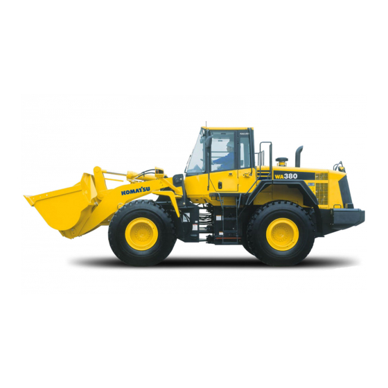
OPERATION GENERAL VIEW GENERAL VIEW GENERAL VIEW OF MACHINE Bucket Turn signal lamp Bell crank Head lamp Front wheel (10) Lift cylinder Bucket cylinder (11) Lift arm Front working lamp (12) Rear working lamp ROPS cab (13) Rear combination lamp Rear wheel 3 - 2... -
Page 60: General View Of Controls And Gauges
OPERATION GENERAL VIEW GENERAL VIEW OF CONTROLS AND GAUGES Gearshift lever stopper (13) Parking brake switch Rear wiper switch (14) Cigarette lighter Front wiper switch (15) Kickdown switch Gearshift lever (16) Lift arm control lever Front switch panel (17) Hold switch Directional lever (18) Bucket control lever... - Page 61 OPERATION GENERAL VIEW MACHINE MONITOR Central warning lamp (21) Auto-greasing pilot lamp (if equipped) Brake oil pressure caution lamp (22) Joystick pilot lamp (if equipped) Enigine oil pressure caution lamp (23) Directional selector pilot lamp Water separtor caution lamp (24) Shift indicator Radiator coolant level caution lamp (25)
- Page 62 OPERATION GENERAL VIEW SWITCH PANEL Right switch panel Front switch panel Transmission shift mode selector switch Machine monitor mode selector switch 1 Transmission cut-off switch (10) Machine monitor mode selector switch 2 Transmission cut-off set swtich (11) Front working lamp switch Emergency steering switch (12) Rear working lamp switch...
-
Page 63: Explanation Of Components
The indicator gauges and meters are actuated after the above system check is completed. The character display shows "KOMATSU" for 3 seconds. If the lamps do not light up, there is probably a failure or disconnection, so contact your Komatsu distributor for inspection. 3 - 6... - Page 64 OPERATION EXPLANATION OF COMPONENTS TYPES OF WARNING If an abnormality occurs on the machine, or if any switch or lever is operated accidently, the monitor display and buzzer give a warning to inform the operator. Following are the types of warning depending on the level of danger.
- Page 65 When the starting switch is at the OFF position, if the service meter is displayed even though the top ( ) of machine monitor mode selector switch 1 is not being pressed, there is probably a failure in the machine, so please contact your Komatsu distributor for inspection.
- Page 66 If action code E03 is displayed, stop the machine immediately and check the failure code. For details, see "FAILURE CODE DISPLAY (PAGE 3-11)". Inform your Komatsu distributor of the failure code and ask for repairs. If there is a failure on the machine, if it is necessary to change the method of operation, or if inspection or maintenance must be carried out, action code E01, E02, or E03 is displayed on the character display in display portion (2).
- Page 67 OPERATION OPERATION EXPLANATION OF COMPONENTS EXPLANATION OF COMPONENTS E01: When a failure occurs in the mechanical system, such as a drop in the level of the engine coolant, the maintenance location is displayed. If the maintenance caution lamp lights up at the same time, inspect and perform maintenance of the item indicated after completion of the day's work or when changing shifts.
- Page 68 If an action code is displayed on the character display, check the failure code according to the failure code display method given below. When contacting your Komatsu distributor to request repairs, inform your distributor of the failure code. Method of displaying failure code 1.
- Page 69 OPERATION EXPLANATION OF COMPONENTS FILTER, OIL REPLACEMENT TIME DISPLAY After completion of the system check and when the starting switch is in the ON position, if any filter or oil item is approaching the replacement time, this display (4) shows the item for approx. 30 seconds.
- Page 70 OPERATION EXPLANATION OF COMPONENTS REMARK See the section below for details of the procedure for replacing the filter and oil. Engine oil "CHANGE OIL IN ENGINE OIL PAN, REPLACE ENGINE OIL FILTER CARTRIDGE (PAGE 4-48)" Engine oil filter "CHANGE OIL IN ENGINE OIL PAN, REPLACE ENGINE OIL FILTER CARTRIDGE (PAGE 4-48)" Fuel pre-filter "REPLACE FUEL PRE-FILTER CARTRIDGE (PAGE 4-49)"...
- Page 71 OPERATION EXPLANATION OF COMPONENTS EMERGENCY STOP ITEMS CAUTION If these lamps light up and the buzzer sounds, stop operations immediately and carry out inspection and maintenance of the applicable location. If any abnormality is found in the emergency stop items, the alarm buzzer will sound intermittently, and the lamp for the location of the abnormality and the central warning lamp will light up.
- Page 72 OPERATION EXPLANATION OF COMPONENTS During operation (engine running) If the brake oil pressure goes down during operation, the brake oil pressure caution lamp and central warning lamp light up and the alarm buzzer sounds intermittently. At the same time, the top line of the character display displays "E03" and the bottom line displays "CHECK RIGHT NOW"...
- Page 73 OPERATION EXPLANATION OF COMPONENTS STEERING OIL PRESSURE CAUTION LAMP (If equipped) (Red) This lamp (4) lights up to warn the operator that the steering oil pressure has dropped. During checks before starting (when the starting switch is turned to the ON position but the engine is not started), this monitor does not light up.
- Page 74 OPERATION EXPLANATION OF COMPONENTS CAUTION ITEMS CAUTION If these lamps light up, stop operations quickly and carry out the following action. Brake oil temperature caution lamp Hydraulic oil temperature caution lamp Torque converter oil temperature caution lamp Fuel level caution lamp Engine coolant temperature caution lamp 3 - 17...
- Page 75 OPERATION EXPLANATION OF COMPONENTS BRAKE OIL TEMPERATURE CAUTION LAMP This lamp (1) lights up to warn the operator that the brake oil temperature has risen. During checks before starting (when the starting switch is turned to the ON position but the engine is not started), this monitor does not light up.
- Page 76 OPERATION EXPLANATION OF COMPONENTS ENGINE COOLANT TEMPERATURE CAUTION LAMP This lamp (3) warns the operator that the engine coolant temperature has risen. During checks before starting (when the starting switch is turned to the ON position but the engine is not started), this monitor does not light up.
- Page 77 OPERATION EXPLANATION OF COMPONENTS INSPECTION AND MAINTENANCE ITEMS CAUTION If these lamps light up, stop operations quickly and carry out the following action. Radiator coolant level caution lamp Water separtor caution lamp Engine oil level caution lamp Transmission oil filter clogging caution lamp Battery electrolyte level caution lamp(if equipped) Maintenance caution lamp Air cleaner clogging caurion lamp...
- Page 78 OPERATION EXPLANATION OF COMPONENTS ENGINE OIL LEVEL CAUTION LAMP This lamp (2) lights up to warn the operator that the oil level in the engine oil pan has gone down. During checks before starting (when the starting switch is turned to the ON position but the engine is not started), this monitor lights up if the oil level in the engine oil pan is low.
- Page 79 OPERATION EXPLANATION OF COMPONENTS AIR CLEANER CLOGGING CAUTION LAMP (Machines equipped with KOMTRAX) This lamp (5) lights up if the air cleaner element becomes clogged when the engine is running. During checks before starting (when the starting switch is turned to the ON position but the engine is not started), this monitor does not light up.
- Page 80 OPERATION EXPLANATION OF COMPONENTS PILOT DISPLAY PORTION When the starting switch is ON, the pilot display lights up when the display items are functioning. Parking brake pilot lamp Directional selector pilot lamp Cooling fan reverse rotation pilot lamp (10) Economy operation display lamp Emergency steering pilot lamp (if equipped) (11) Shift indicator...
- Page 81 OPERATION EXPLANATION OF COMPONENTS COOLING FAN REVERSE ROTATION PILOT LAMP This lamp (2) lights up when the direction of rotation of the cooling fan is reversed. At the same time, "COOLING FAN REVERSE" is displayed on the character display. For details of the method of operation, see "COOLING FAN REVERSE ROTATION SWITCH (PAGE 3-50)".
- Page 82 OPERATION EXPLANATION OF COMPONENTS PREHEATING PILOT LAMP This lamp (5) lights up when the engine preheating electric heater is actuated. In cold weather, when the starting switch is turned to the ON position, this lamp lights up. It goes out when preheating is completed.
- Page 83 OPERATION EXPLANATION OF COMPONENTS SHIFT INDICATOR This monitor (11) indicates the transmission gear range (actual travel speed range). AUTO-SHIFT PILOT LAMP This lamp (12) lights up when the auto-shift function is selected. Use the transmission shift mode selector switch to select the shift mode.
- Page 84 OPERATION EXPLANATION OF COMPONENTS SHIFT LEVER POSITION PILOT LAMP This lamp (15) displays the transmission position of the gearshift lever. TURN SIGNAL PILOT LAMP This lamp (16) flashes at the same time as the turn signal lamp flashes. REMARK If there is a disconnection in the turn signal lamp, the flashing interval becomes shorter.
- Page 85 OPERATION EXPLANATION OF COMPONENTS METER DISPLAY PORTION Torque converter oil temperature gauge Fuel gauge Engine coolant temperature gauge Speedometer Hydraulic oil temperature gauge Meter display pilot lamp TORQUE CONVERTER OIL TEMPERATURE GAUGE This meter (1) indicates the torque converter oil temperature. It should be in white range (A) during operations.
- Page 86 The display unit is indicated on meter display pilot lamp (6). It is also possible to display the engine speed by switching meter (5). If you wish to switch between the speedometer and tachometer, please contact your Komatsu distributor to have it switched. 3 - 29...
- Page 87 OPERATION EXPLANATION OF COMPONENTS METER DISPLAY PILOT LAMP This lamp (6) displays the unit for the travel speed or engine tachometer. 3 - 30...
- Page 88 OPERATION EXPLANATION OF COMPONENTS OTHER FUNCTIONS OF MACHINE MONITOR The machine monitor also has the following functions. Odometer, filter/oil replacement time reset, telephone number input, language selection, monitor brightness adjustment 3 - 31...
- Page 89 OPERATION EXPLANATION OF COMPONENTS METHOD OF DISPLAYING ODOMETER Use this when checking the total distance that the machine has traveled. 1. Check that the character display is displaying the service meter or an action code. If there is any other display, turn the starting switch OFF, then turn the starting switch ON again and wait for the service meter display or action code display to appear.
- Page 90 OPERATION EXPLANATION OF COMPONENTS RESET METHOD FOR FILTER, OIL REPLACEMENT TIME The filter and oil replacement time is displayed on the character display, so if the filter and oil have been replaced, reset the filter and oil change time. 1. Press the ( ) of machine monitor mode selector switch 1, and display the odometer. 2.
- Page 91 OPERATION EXPLANATION OF COMPONENTS INPUT METHOD FOR TELEPHONE NUMBER It is possible to display the telephone number on the right side of "CALL" displayed on the character display when action code "E03" is generated. 1. Press the ( ) of machine monitor mode selector switch 1, and display the odometer. 2.
- Page 92 OPERATION EXPLANATION OF COMPONENTS METHOD FOR SELECTING LANGUAGE Use this when switching the language displayed on the character display. The following explanation is for when English is set as the language for the character display. 1. Press the ( ) of machine monitor mode selector switch 1, and display the odometer. 2.
- Page 93 OPERATION EXPLANATION OF COMPONENTS METHOD OF ADJUSTING MONITOR BRIGHTNESS Do as follows to adjust the brightness of the monitor. 1. Press the ( ) of machine monitor mode selector switch 1, and display the odometer. 2. Press (>) or (<) of machine monitor mode selector switch 2 and display "BRIGHTNESS ADJUST".
- Page 94 OPERATION EXPLANATION OF COMPONENTS METHOD OF SWITCHING TRAVEL SPEED/ENGINE SPEED DISPLAY Use this when switching between the travel speed (km/h, MPH) and the engine speed display. 1. Press the ( ) portion of the machine monitor mode selector switch 1 to display "ODO" (odometer). 2.
- Page 95 OPERATION EXPLANATION OF COMPONENTS METHOD OF SWITCHING TRAVEL SPEED/ENGINE SPEED DISPLAY/NON-DISPLAY Use the following method to display the travel speed or engine speed or to have no display on the character display. 1. Press the ( ) portion of the machine monitor mode selector switch 1 to display "ODO"...
-
Page 96: Switches
OPERATION EXPLANATION OF COMPONENTS SWITCHES 3 - 39... - Page 97 OPERATION OPERATION EXPLANATION OF COMPONENTS EXPLANATION OF COMPONENTS Starting switch (13) Machine monitor mode selector switch 2 Power mode selector switch (14) Kickdown switch Transmission shift mode selector switch (15) Hold switch Transmission cut-off switch (16) Front wiper switch Transmission cut-off set switch (17) Rear wiper switch Lamp switch...
- Page 98 OPERATION EXPLANATION OF COMPONENTS POWER MODE SELECTOR SWITCH This switch (2) can be used to switch the engine output to match the purpose of the operation. When the P mode is selected, the power mode pilot lamp (P mode) on the machine monitor lights up. Position (a): E mode (engine output low);...
- Page 99 OPERATION EXPLANATION OF COMPONENTS TRANSMISSION CUT-OFF SWITCH WARNING When starting the machine off up a hill, turn the transmission cut-off switch to the OFF position, depress the brake pedal, then gradually depress the accelerator pedal and release the brake slowly to allow the machine to start off. This makes it possible to prevent the machine from rolling back.
- Page 100 OPERATION EXPLANATION OF COMPONENTS LAMP SWITCH This switch (6) is used to light up the front lamps, side clearance lamps, tail lamps, and instrument panel. Position (a): OFF Position (b): Side clearance lamps, tail lamps, and instrument panel light up Position (c): Head lamps light up in addition to lamps at (b) position REMARK The lamp switch can be operated regardless of the position of the...
- Page 101 Apply the parking brake only after the machine has stopped. If the parking brake has been used as an emergency brake when traveling at high speed, contact your Komatsu distributor to have the parking brake checked for any abnormality.
- Page 102 OPERATION EXPLANATION OF COMPONENTS FRONT WORKING LAMP SWITCH WARNING Always turn the working lamp off before traveling on public roads. This switch (10) is used to light up the front working lamp. Position (a): Working lamp lights up Position (b): Working lamp goes out If position (a) is pressed, the pilot lamp will light up and the working lamp circuit will be switched ON.
- Page 103 OPERATION EXPLANATION OF COMPONENTS MACHINE MONITOR MODE SELECTOR SWITCH 2 This switch (13) is used to switch the function of the character display. When the switch is released, it automatically returns to its original position. The basic operation is as follows. Position (>): Press here to go on to the next screen, or to move the cursor forward, or to increase the number when entering numerals...
- Page 104 OPERATION EXPLANATION OF COMPONENTS REMARK When canceling the kick-down, operate the directional lever. In manual shift, the kick-down can be canceled by operating the gearshift lever to any position other than 2nd. It is also possible to cancel the kick-down by turning the starting switch OFF.
- Page 105 OPERATION EXPLANATION OF COMPONENTS REAR WIPER SWITCH When lever (E) of this switch (17) is turned, the rear wiper will move. Position (A): Washer liquid is sprayed out Position (B): OFF Position (C): Wiper is operated Position (D): Washer liquid is sprayed out, wiper is operated CIGARETTE LIGHTER This is used to light cigarettes.
- Page 106 OPERATION EXPLANATION OF COMPONENTS E.C.S.S. (ELECTRONIC CONTROLLED SUSPENSION SYSTEM) SWITCH WARNING If the machine is traveling or the work equipment is raised, the moment the E.C.S.S. switch is turned ON, the work equipment will move. If operations are carried out with the E.C.S.S. switch at the ON position, the moment the E.C.S.S. is actuated, the work equipment may move.
- Page 107 OPERATION EXPLANATION OF COMPONENTS The time for operating the emergency steering continuously is a maximum of 60 seconds. When using the emergency steering, travel at a speed of less than 5 km/h (3.1 MPH). For details, see "EMERGENCY STEERING (PAGE 3-137)" in the OPERATION section. COOLING FAN REVERSE ROTATION SWITCH This switch (23) is used to rotate the cooling fan in the reverse direction when cleaning the radiator.
- Page 108 It is possible to adjust the following of the automatic reverse rotation functions: Cycle fan automatic reverse rotation (Standard: 2 hours) Continuous time fan automatic reverse rotation (Standard: 2 minutes) Please ask your Komatsu distributor to carry out the adjustment Conditions for switching fan rotation When using manual reverse rotation function Switching from normal rotation to reverse rotation The fan will switch from normal rotation to reverse rotation only if all the following conditions are fulfilled.
- Page 109 OPERATION EXPLANATION OF COMPONENTS Conditions More than 10 minutes have passed after the fan started to rotate in reverse and the engine speed has dropped to less than 1200 rpm. When portion (b) of the cooling fan automatic reverse rotation switch is pressed again when the fan is rotating in reverse, and the engine speed has dropped to less than 1200 rpm.
-
Page 110: Control Levers, Pedals
OPERATION EXPLANATION OF COMPONENTS CONTROL LEVERS, PEDALS Gearshift lever Bucket control lever Directional lever Lift arm control lever Gearshift lever stopper Brake pedal Work equipment lock lever Accelerator pedal GEARSHIFT LEVER This lever (1) changes the speed range of the transmission. MANUAL SHIFT This machine has a 4-FORWARD, 4-REVERSE speed transmission. - Page 111 EXPLANATION OF COMPONENTS REMARK The lever length can be set to 3 levels (positions (A), (B), and (C)). For adjustment, consult your Komatsu distributor. (The lever is installed to position (B) when delivered.) AUTOMATIC SHIFT Automatic gear shifting can be carried out in the 2nd through 4th speed range of the four forward and reverse speeds depending on the travel conditions.
- Page 112 Position (R): Reverse REMARK The lever length can be set to 2 levels (positions (A), (B)). For adjustment, consult your Komatsu distributor. (The lever is installed to position (A) when delivered.) GEARSHIFT LEVER STOPPER This stopper (3) prevents the gearshift lever from entering the 3rd or 4th positions when working.
- Page 113 OPERATION EXPLANATION OF COMPONENTS WORK EQUIPMENT LOCK LEVER WARNING Before standing up from the operator's seat, set the work equipment lock lever securely to the LOCK position. If the work equipment lock lever is not at the LOCK position, and work equipment control lever(A) is touched by mistake, it may lead to a serious accident.
- Page 114 OPERATION EXPLANATION OF COMPONENTS LIFT ARM CONTROL LEVER This lever (6) is used to operate the lift arm. NOTICE Do not use the FLOAT position when lowering the bucket. Use the FLOAT position when leveling, see "LEVELING OPERATIONS (PAGE 3-145)". Position (a): RAISE When the lift arm control lever is pulled further from the RAISE position, the lever is stopped in this...
-
Page 115: Steering Tilt Lock Lever
OPERATION EXPLANATION OF COMPONENTS ACCELERATOR PEDAL This pedal (8) controls the engine speed and output. The engine speed can be freely controlled between low idle and full speed. STEERING TILT LOCK LEVER WARNING Stop the machine before adjusting the tilt of the steering wheel. If this operation (adjustment) is carried out while the machine is moving, it may lead to a serious accident or personal injury. - Page 116 OPERATION EXPLANATION OF COMPONENTS METHOD OF OPENING AND CLOSING CAP WITH LOCK (FOR THE FUEL TANK FILLER PORT) TO OPEN THE CAP 1. Insert the key into the key slot. 2. Turn the key clockwise, align the key groove with mark (1) on the cap, then open the cap.
-
Page 117: Frame Lock Bar
OPERATION EXPLANATION OF COMPONENTS FRAME LOCK BAR WARNING When carrying out maintenance or transporting the machine, always set the frame lock bar to the LOCK position. Always remove the frame lock bar for travel operations. If it is not removed, the steering wheel cannot be used for steering, and this may lead to serious damage or injury. -
Page 118: Grease Pump
OPERATION EXPLANATION OF COMPONENTS GREASE PUMP The grease pump is installed in the holder on the left radiator side of the engine bulkhead at the rear of the machine. After using it, wipe off the grease from its outside and install it in position. Insert the grease pump in the holder and fix it with the rubber band. - Page 119 OPERATION EXPLANATION OF COMPONENTS OPENING, CLOSING CAB DOORS, WINDOWS CAUTION Always check that the cab door is locked, both when it is open and when it is closed. Always stop the machine on level ground before opening or closing the door.
- Page 120 OPERATION EXPLANATION OF COMPONENTS DOOR OPEN LOCK When getting in or out of the operator's compartment, or when operating with the door open, use this lock to hold the door in position. 1. Push the door against catch (1) to lock it in position. 2.
- Page 121 OPERATION EXPLANATION OF COMPONENTS OPEN LOCK KNOB FOR CAB EMERGENCY ESCAPE DOOR CAUTION The door on the right side of the cab is provided as an emergency escape door for use when it is impossible to exit from the door on the left side. Do not use it as the door for normal entry and exit from the cab. Never operate the machine with the door open to around 90 degrees.
- Page 122 OPERATION OPERATION EXPLANATION OF COMPONENTS EXPLANATION OF COMPONENTS 2. Grip open lock knob (1) and pull it towards the rear of the machine. 3. Remove the open lock guide rail from the window pillar guide to free the right window lock. 4.
-
Page 123: Backup Alarm
OPERATION EXPLANATION OF COMPONENTS BACKUP ALARM This sounds an alarm when the directional lever is set to the R position. It is used to warn people behind the machine that the machine will travel in reverse. 3 - 66... -
Page 124: Fuse
OPERATION EXPLANATION OF COMPONENTS FUSE NOTICE Before replacing a fuse, be sure to turn off the starting switch. The fuses protect the electrical equipment and wiring from burning out. If the fuse becomes corroded, or white powder can be seen, or the fuse is loose in the fuse holder, replace the fuse. Replace the fuse with another of the same capacity. -
Page 125: Slow Blow Fuse
OPERATION EXPLANATION OF COMPONENTS FUSE BOX B Fuse Name of circuit capacity Engine control B Rear heated wire glass Air suspension seat Yellow rotating lamp(if equipped) Turn signal indicator Car radio, cigarette lighter, 12V power source Rear working lamp Front working lamp Spare 1 (10) Engine control A... -
Page 126: Power Outlet
OPERATION EXPLANATION OF COMPONENTS POWER OUTLET NOTICE There are two power sources: 12V (if equipped) and 24V Check the voltage of the electrical equipment and select the appropriate power source. Mistaken use, such as using 24V as the power source for 12V equipment, will cause failure of the equipment. When using the electric power source, do not install any equipment which will exceed the maximum amperage. -
Page 127: Am/Fm Radio
OPERATION EXPLANATION OF COMPONENTS AM/FM RADIO (If equipped) EXPLANATION OF COMPONENTS Power switch/Volume Preset switch Tone control knob Seek Display Band selector switch Clock button/Displaying frequency Tuning switch POWER SWITCH/VOLUME When this switch (1) is turned to the right, it clicks and the power is turned on. - Page 128 OPERATION EXPLANATION OF COMPONENTS TONE CONTROL KNOB If this knob (2) is turned to the right, the high tone is emphasized; if it is turned to the left, the high tone is reduced. DISPLAY This display (3) shows the radio reception frequency and the operating mode.
- Page 129 OPERATION EXPLANATION OF COMPONENTS PRESET SWITCH With this switch (6), each button can be preset to one station each for FM and MW (AM). (For details of the method of presetting, see Section "METHOD OF PRESETTING STATION (PAGE 3-74)".) SEEK When this switch (7) ("SEEK") is pressed, it automatically searches for stations that can be received, and when it receives a station, it stops.
- Page 130 OPERATION EXPLANATION OF COMPONENTS METHOD OF OPERATION LISTENING TO RADIO 1. Turn radio power switch (1) ON. 2. "BAND" switch (2) is used to select MW (AM) or FM. 3. Use the preset switch or tuning switch (3) to select the station. 4.
- Page 131 OPERATION EXPLANATION OF COMPONENTS METHOD OF PRESETTING STATION 1. Select the desired preset station. Use the "BAND" button to select MW (AM) or FM, and use the "TUNE" button to select the frequency of the broadcasting station. 2. Decide the number of the button to be preset, and keep it pressed for 2 seconds.
- Page 132 OPERATION EXPLANATION OF COMPONENTS METHOD OF SETTING TIME 1. Turn radio power (1) ON. If the display (2) is set to a frequency, press TIME button (3) to display the time. 2. With TIME button (3) kept pressed: Press button (4) to set the minutes. Press button (5) to set the hours.
-
Page 133: Am/Fm Radio-Cassette Stereo
OPERATION EXPLANATION OF COMPONENTS AM/FM RADIO-CASSETTE STEREO (If equipped) EXPLANATION OF COMPONENTS Power switch/volume Cassette door Auto-store/preset scan button Fast forward, rewind buttons Bass control knob (10) Preset buttons Treble control knob (11) Metal tape button Loudness button (12) Manual tuning buttons Time/radio display selector button (13) Seek tuning buttons... - Page 134 OPERATION EXPLANATION OF COMPONENTS POWER SWITCH/VOLUME Turn this knob (1) to the right until it clicks to turn the power on. Turn it further to increase the volume. AUTO-STORE/PRESET SCAN BUTTON Use this button (2) to actuate the preset scan and auto-store functions.
- Page 135 OPERATION EXPLANATION OF COMPONENTS TREBLE CONTROL KNOB Turn this button (4) to the left to reduce the low tones; turn it to the right to emphasize the high tones. Direction (a): High tone reduced Direction (b): High tone emphasized LOUDNESS BUTTON This button (5) is used when playing at low volume.
- Page 136 OPERATION EXPLANATION OF COMPONENTS TAPE EJECT BUTTON This button (7) is used to stop the tape and to eject the cassette. When this button is pressed, the tape is ejected and the radio plays. CASSETTE DOOR Set the cassette with the exposed portion of the tape on the right side and insert it through the cassette door (8).
- Page 137 OPERATION EXPLANATION OF COMPONENTS METAL TAPE BUTTON (used also for preset button No. 5) This button (11) is used when playing a metal or chrome tape. This button is also used for preset button No. 5. When it is pressed, "MTL"...
- Page 138 OPERATION EXPLANATION OF COMPONENTS METHOD OF OPERATION METHOD OF SETTING PRESET BUTTONS It is possible to preset 6 MW (AM) stations and 12 FM stations (FM1: 6 stations, FM2: 6 stations). REMARK If you are playing the cassette, press the tape eject button to stop the tape. METHOD OF AUTO PRESET 1.
- Page 139 OPERATION EXPLANATION OF COMPONENTS LISTENING TO RADIO 1. Turn the starting switch ON, then turn power switch (1) ON. 2. Use band selector button (2) to select MW (AM), FM1 or FM2. 3. Select the station with the preset buttons (3). REMARK In case you do not promptly remember the number assigned to a certain preset station, press auto-store/preset scan button (4) for...
- Page 140 If the sound cannot be heard, nothing is displayed, or any other problem occurs, turn off the power switch and ask your Komatsu distributor to make repairs without delay. Stow the antenna when traveling in places with low overhead clearance.
-
Page 141: Handling Auto Air Conditioner
OPERATION EXPLANATION OF COMPONENTS HANDLING AUTO AIR CONDITIONER By taking fresh air into the cab through a filter, it is possible to raise the pressure inside the cab. This makes it possible to provide a pleasant working environment even on dusty jobsites. NAMES AND FUNCTIONS OF ITEMS ON CONTROL PANEL Main power switch Temperature control switch... -
Page 142: Main Power Switch
OPERATION EXPLANATION OF COMPONENTS MAIN POWER SWITCH Use the switch (1) to turn the main power of the air conditioner ON/OFF. When the switch is pressed, display monitor (A) lights up. The fan begins operation. When the switch is pressed again, the air conditioner is turned OFF and the display monitor goes out. -
Page 143: Fan Switch
OPERATION EXPLANATION OF COMPONENTS FAN SWITCH Use this switch (2) to adjust the air flow from the fan. The air flow can be adjusted to 4 levels. When this switch (A) is pressed, the air flow increases; when switch (B) is pressed, the air flow decreases. The setting for the air flow is displayed on the display monitor. -
Page 144: Air Conditioner Switch
OPERATION EXPLANATION OF COMPONENTS AIR CONDITIONER SWITCH Use this switch (3) to start and stop the cooling or dehumidifying heating function. When the main power switch is ON, if the air conditioner switch is pressed, the air conditioner is turned ON and (A) is displayed on the display monitor. - Page 145 OPERATION EXPLANATION OF COMPONENTS RECIRC/FRESH SELECTOR SWITCH Use this switch (6) to switch between recirculation of the air inside the cab and intake of fresh air from outside. When this switch is pressed, recirculation of inside air is selected and (A) lights up on the display monitor. If the switch is pressed again, intake of fresh air is selected and (B) lights up on the display monitor.
- Page 146 OPERATION EXPLANATION OF COMPONENTS HEATING OPERATION 1. Press main power switch (1) of the air conditioner to turn the power ON. 2. Press fan switch (2) and set the air flow to "Hi". 3. Press temperature control switch (3) to set to the desired temperature.
- Page 147 To allow the air conditioner to show its full performance and provide a comfortable environment, have inspection and maintenance carried out periodically. When adding refrigerant or carrying out other maintenance, special tools and instruments are needed, so ask your Komatsu distributor to carry out inspection and repair. 3 - 90...
-
Page 148: Air Conditioner
OPERATION EXPLANATION OF COMPONENTS AIR CONDITIONER (If equipped) By taking fresh air into the cab through a filter, it is possible to raise the pressure inside the cab. This makes it possible to provide a pleasant working environment even on dusty jobsites. GENERAL LOCATIONS AND FUNCTION OF CONTROL PANEL Main power switch Temperature control switch... - Page 149 OPERATION EXPLANATION OF COMPONENTS MAIN POWER SWITCH Use the switch (1) to turn the main power of the air conditioner ON/OFF. When the switch is pressed, display monitor (A) lights up. The fan begins operation. When the switch is pressed again, the air conditioner is turned OFF and the display monitor goes out.
- Page 150 OPERATION EXPLANATION OF COMPONENTS FAN SWITCH Use this switch (2) to adjust the air flow from the fan. The air flow can be adjusted to 4 levels. When this switch (A) is pressed, the air flow increases; when switch (B) is pressed, the air flow decreases. The setting for the air flow is displayed on the display monitor.
- Page 151 OPERATION EXPLANATION OF COMPONENTS AIR CONDITIONER SWITCH Use this switch (3) to start and stop the cooling or dehumidifying heating function. When the main power switch is ON, if the air conditioner switch is pressed, the air conditioner is turned ON and (A) is displayed on the display monitor.
-
Page 152: Fresh/Recirc Selector Switch
OPERATION EXPLANATION OF COMPONENTS FRESH/RECIRC SELECTOR SWITCH Use this switch (5) to switch between recirculation of the air inside the cab and intake of fresh air from outside. When this switch is pressed, recirculation of inside air is selected and (A) lights up on the display monitor. If the switch is pressed again, intake of fresh air is selected and (B) lights up on the display monitor. - Page 153 OPERATION EXPLANATION OF COMPONENTS METHOD OF OPERATION COOLING OPERATION 1. Press main power switch (1) of the air conditioner to turn the power ON. 2. Press fan switch (2) and set the air flow to "Hi". 3. Press temperature control switch (3) and set the display monitor to COOL (A).
- Page 154 When adding refrigerant or carrying out other maintenance, special tools and instruments are needed, so ask your Komatsu distributor to carry out inspection and repair. COOL BOX When the cooling is being used, this can be used for keeping drinks and other things cool.
-
Page 155: Handling Cab Wiper
OPERATION EXPLANATION OF COMPONENTS HANDLING CAB WIPER PREVENTING DAMAGE TO WIPER ARM BRACKET NOTICE When angling the wiper arm (1) to the front, check that the wiper blade is hanging free. When angling the wiper arm (1) to the front, such as when wiping the glass clean, if the wiper arm (1) is angled with the wiper blade (2) locked to the arm (the bottom of the blade is caught on the arm), abnormal force is brought to bear on the mounting bracket and the... -
Page 156: Operation
Remove any flammable materials from around the battery, engine, muffler, turbocharger, or other high temperature engine parts. Leakage of fuel or oil will cause the machine to catch fire. Check carefully, be sure to repair any problem, or contact your Komatsu distributor. - Page 157 OPERATION OPERATION 8. Check for damage and loose bolts on the handrail and steps. Repair any damage and tighten any loose bolts. 9. Check for damage to gauges, lamps on the instrument panel and loose bolts. Check for damage to the panel, gauges and lamps. If any problem is found, replace the parts. Clean off any dirt on the surface.
- Page 158 OPERATION OPERATION 12. Check for damage to the seat belt and mounting clamps. WARNING Before fitting the seat belt, check that there is no problem in the belt mount bracket or mounting belt. If it is worn or damaged, replace the seat belt. Even if there are no signs of damage, replace belts in accordance with the following schedule: 5 years after the date of seat belt manufacture, or every 3 years after the start of actual usage, whichever date comes first.
- Page 159 OPERATION OPERATION 14. Inspect tires. WARNING If worn or damaged tires are used, they may burst and cause serious injury or death. To ensure safety, do not use the following tires. Wear: Tires with a tread grooves of less than 15% of that of a new tire Tires with extreme uneven wear or with stepped-type wear Damage: Tires with damage that has reached the cords (1), or with cracks in the...
- Page 160 2. Check that all the monitors, gauges, and the central warning lamp light up for approx. 2 seconds, and that the alarm buzzer sounds for approx. 2 seconds. If the lamps do not light up, there is probably a failure or disconnection. Contact your Komatsu distributor inspection. 3 - 103...
- Page 161 OPERATION OPERATION CHECK COOLANT LEVEL, ADD COOLANT WARNING Do not open the radiator cap unless necessary. Wait for the engine to cool down before checking the coolant in the sub-tank. Immediately after the engine is stopped, the coolant is at a high temperature and the radiator is under high internal pressure. If the cap is removed to check the coolant level in this condition, there is a hazard of burns.
- Page 162 OPERATION OPERATION CHECK OIL LEVEL IN ENGINE OIL PAN, ADD OIL WARNING Parts and oil are at high temperature immediately after the engine is stopped and may cause serious burns. Wait for the oil temperature to go down before performing this operation. 1.
- Page 163 OPERATION OPERATION CHECK WATER SEPARATOR WARNING Each part of the engine is still highly heated immediately after the engine is stopped. Do not attempt to drain cooling water or remove the filter element cup. High pressure is generated inside the engine fuel piping, while the engine is running. Wait for more than 30 seconds after the engine stop for the engine to sufficiently cool down.
- Page 164 OPERATION OPERATION OPERATION OPERATION REMARK If plug (2) is stiff, coat O-ring (5) of plug (2) with grease. 1) Set a fuel container under drain hose (4). 2) Loosen plug (2), then drain all the sediment together with the fuel from drain hose (4). 3) Check that nothing comes out from drain hose (4), then remove plug (2).
- Page 165 OPERATION OPERATION CHECK AIR CLEANER WARNING If inspection, cleaning, or maintenance is carried out with the engine running, dirt will get into the engine and damage it. Always stop the engine before carrying out these operations. When using compressed air, there is danger that dirt may be blown around and cause serious injury. Always use protective glasses, dust mask, and other protective equipment.
- Page 166 OPERATION OPERATION CHECK FUEL LEVEL, ADD FUEL WARNING When filling with fuel, do not add any more fuel after the fuel supply has automatically stopped. If too much fuel is added, there is danger that the fuel may expand because of the rise in the ambient temperature and cause the fuel to overflow. Spilled fuel may cause fire, so always wipe off any spilled fuel completely.
- Page 167 If the fluid does not spray out properly, clean the washer nozzle with a safety pin or thin wire. If the condition is still not improved, please ask your Komatsu distributor to carry out inspection and repair. CHECK WIPING EFFICIENCY OF WIPER Operate the wiper and check that it wipes the window properly under each operating speed: Intermittent, low speed, high speed.
- Page 168 OPERATION CHECK EMERGENCY EXIT Operate the knob for opening and closing the emergency exit, and check that it works properly. If any abnormality is found, please ask your Komatsu distributor to carry out inspection and repair. ADJUSTMENT SEAT ADJUSTMENT WARNING When adjusting the position of the operator's seat, always set the work equipment lock lever to the LOCK position to prevent any accidental contact with the control levers.
- Page 169 OPERATION OPERATION (D) Adjusting fore-and-aft position of seat cushion Push in lever (4), set the seat cushion to the desired position, then release the lever. Amount of adjustment: 60 mm (2.4 in) (E) Setting seat for weight Sit on the seat, raise your body slightly, then operate switch (5) to adjust the strength of the suspension. Amount of adjustment: 50 - 130 kg (110 - 287 lb)(target) When + is pressed: Suspension becomes stronger When - is pressed: Suspension becomes weaker...
- Page 170 OPERATION OPERATION REMOVAL AND INSTALLATION OF HEADREST REMOVAL If the headrest is not needed, remove it as follows. 1. Pull up the headrest to the position where it stops. 2. From the top of the seat back, turn stopper (1) (under the material at the top of the seat) of the headrest bar on one side in the direction of the arrow, and pull up the headrest.
- Page 171 OPERATION OPERATION ADJUST SEAT BELT Always wear the seat belt. WARNING Before fastening the seat belt, check that there is no abnormality in the belt-mounting bracket or mounting of the belt. If the belt is worn or damaged, replace it. Even if there are no signs of damage, replace belts in accordance with the following schedule: 5 years after the date of seat belt manufacture, or every 3 years after the start of actual usage, whichever date comes first.
- Page 172 OPERATION OPERATION OPERATION OPERATION To make belt longer: Set the fixed end of the tether belt at 90 degrees to the holder, and pull. ADJUST LEVER STAND WARNING When adjusting the lever stand, check that the work equipment lock lever is securely at the LOCK position. If it is not at the LOCK position, and the work equipment control levers are touched by accident when adjusting the lever stand, the work equipment may suddenly move and cause serious personal injury.
- Page 173 Tightening torque Mirrors A, B :2.0 to 2.5Nm{0.2 to 0.25 kgm} Mirrors C :8.8 to 9.8Nm{0.9 to 1.0 kgm} If the tightening torque cannot be controlled, ask your Komatsu distributor for tightening the bolts. 3 - 116...
- Page 174 OPERATION OPERATION OPERATIONS AND CHECKS BEFORE STARTING ENGINE WARNING When starting the engine, check that the work equipment lock lever are placed securely at the LOCK position. If the work equipment control lever is touched by accident when the engine is started, the work equipment may move unexpectedly and cause serious injury or damage.
- Page 175 If any monitor does not light up, there is probably a failure or disconnection. Contact your Komatsu distributor inspection. In addition, after all the monitors, gauges, and central warning lamp light up, a self check is carried out to check that the emergency steering function works properly.
-
Page 176: Starting Engine
OPERATION OPERATION STARTING ENGINE NORMAL STARTING WARNING Sit down in the operator's seat before starting the engine. Do not attempt to start the engine by short-circuiting the engine starting circuit. Such an act may cause serious bodily injury or fire. Check that there are no persons or obstacles in the surrounding area, then sound the horn and start the engine. - Page 177 OPERATION OPERATION OPERATION OPERATION 2. If the preheating pilot lamp (2) does not light up, or it lights up and then goes out to inform that the engine preheating has been completed, turn the key in starting switch (1) to the START position (C).
- Page 178 OPERATION OPERATION STARTING IN COLD WEATHER WARNING Sit down in the operator's seat before starting the engine. Do not attempt to start the engine by short-circuiting the engine starting circuit. Such an act may cause serious bodily injury or fire. Check that there are no persons or obstacles in the surrounding area, then sound the horn and start the engine.
- Page 179 OPERATION OPERATION 4. Method of starting engine in temperatures of approx. -20°C (-4°F). 1) Keep the engine starting motor running for the max. 20 seconds, holding the key of engine starting switch (1) in the START position (C), until the engine starts up. 2) If the engine fails to start up even after running the engine starting motor for about 20 seconds, stop the engine starting motor once (release the engine starting switch (1) key), and try the same process again after a pause for a minute or so.
-
Page 180: Checks After Starting Engine
Set to the machine on level ground with no obstacles in the surrounding area, then drive the machine slowly forward and in reverse and check the braking effect of the brakes. If there is any abnormality in the operation of the brakes, please ask your Komatsu distributor to carry out adjustment. -
Page 181: Operations And Checks After Starting Engine
BREAKING-IN THE MACHINE CAUTION Your Komatsu machine has been thoroughly adjusted and tested before shipment. However, operating the machine under severe conditions at the beginning can adversely affect the performance and shorten the machine life. Be sure to break-in the machine for the initial 100 hours (as indicated by the service meter). - Page 182 (3) are in the green range. 6. Check for abnormal exhaust gas color, noise, or vibration. If any problem is found, contact your Komatsu distributor. REMARK The rotating speed of the cooling fan differs according to the following conditions, but this does not indicate any abnormality.
-
Page 183: Stopping Engine
OPERATION OPERATION STOPPING ENGINE NOTICE If the engine is abruptly stopped before it has cooled down, engine life may be greatly shortened. Consequently, do not abruptly stop the engine except for an emergency. In particular, if the engine has overheated, do not abruptly stop it but run it at medium speed to allow it to cool gradually, then stop it. -
Page 184: Moving The Machine (Directional, Speed), Stopping The Machine
OPERATION OPERATION MOVING THE MACHINE (DIRECTIONAL, SPEED), STOPPING THE MACHINE WARNING Always remove the frame lock bar for travel operations. If it is not removed, the steering wheel cannot be used for steering, and this may lead to serious damage or injury. When moving the machine off, check that the area around the machine is safe, then sound the horn before starting. - Page 185 Position (F): Forward Position (N): Neutral Position (R): Reverse Check that the backup alarm sounds when the directional lever is set to REVERSE. If the backup alarm does not sound, please contact your Komatsu distributor for repairs. 3 - 128...
- Page 186 OPERATION OPERATION OPERATION OPERATION 7. Release right brake pedal (5), then depress accelerator pedal (9) to move the machine off. REMARK When moving the machine off on a hill, turn transmission cut-off switch (10) OFF, depress left brake pedal (11), operate the gearshift lever to the low speed range, then depress accelerator pedal (9) and gradually release left brake pedal (11) to let the machine move off.
- Page 187 OPERATION OPERATION CHANGING GEAR SPEED WARNING When traveling at high speed, do not shift gear suddenly. Use the brake to reduce the travel speed before shifting gear. Shift gear as follows. Move the gearshift lever (1) to the desired position to shift gear. When carrying out digging or loading operations, the operation is carried out in 1st or 2nd, so use the gearshift lever stopper (2).
- Page 188 Check that the backup alarm sounds when the directional lever is set to REVERSE. If the backup alarm does not sound, please contact your Komatsu distributor for repairs. REMARK If the directional lever is operated slowly or is stopped midway between the forward and reverse directions, "E01 MAINTENANCE"...
- Page 189 OPERATION OPERATION WHEN USING AUTO-SHIFT If an attempt is made to switch the direction between forward and reverse when the auto-shift is ON, normally, the gearshift range will switch F3 -> R2, F4 -> R2, or R3 -> F2, R4 -> F2 to make it possible to move the machine off quickly.
- Page 190 OPERATION OPERATION STOPPING THE MACHINE WARNING Avoid stopping suddenly. Give yourself ample room when stopping. Even if the parking brake switch is turned ON, there is danger until the parking brake pilot lamp lights up, so keep the brake pedal depressed. NOTICE Never use the parking brake switch to brake the machine when traveling except in an emergency.
- Page 191 OPERATION OPERATION TRANSMISSION CUT-OFF FUNCTION When the transmission cut-off switch is turned ON, the pilot lamp lights up and the following transmission cut-off function is actuated. Position (a): OFF Position (b): ON When the brake pedal is depressed, the brakes are actuated and the transmission is returned to Neutral when the brake pedal is depressed to the set position.
- Page 192 OPERATION OPERATION ADJUSTING TRANSMISSION CUT-OFF POSITION CAUTION Apply the parking brake before adjusting the transmission cut-off position. Adjust the amount that the brake pedal is depressed for the set position to return the transmission to Neutral. 1. Start the engine with starting switch (1), then set parking brake switch (2) to the ON position.
-
Page 193: Turning
Check that there is a play of 50 to 100 mm (2.0 to 3.9 in) in the steering wheel. Check also that the steering works properly. If any abnormality is found, please contact your Komatsu distributor for inspection. 3 - 136... - Page 194 OPERATION OPERATION EMERGENCY STEERING (If equipped) CAUTION Never actuate the emergency steering except during emergencies or when checking the function. The emergency steering can be used continuously for a maximum of 60 seconds. Operating it continuously for more than 60 seconds may damage the system.
- Page 195 If the steering oil pressure caution lamp (red) or emergency steering pilot lamp (green) do not light up, there is an abnormality, so please ask your Komatsu distributor to carry out inspection. CAUTION If the machine is steered during the steering self-check, it may move.
-
Page 196: Operation Of Work Equipment
OPERATION OPERATION OPERATION OF WORK EQUIPMENT Lift arm control lever (1) and bucket control lever (2) can be used to operate the lift arm and bucket as follows. LIFT ARM CONTROL LEVER NOTICE Do not use the FLOAT position when lowering the bucket. Use the FLOAT position when leveling, see "LEVELING OPERATIONS (PAGE 3-145)". - Page 197 OPERATION OPERATION BUCKET CONTROL LEVER Position (a): TILT When the bucket control lever is pulled further from the TILT position, the lever is stopped in this position until the bucket reaches the preset position of the positioner, and the lever is returned to the HOLD position.
-
Page 198: Work Possible Using Wheel Loader
OPERATION OPERATION WORK POSSIBLE USING WHEEL LOADER In addition to the following, it is possible to further increase the range of applications by using various attachments. DIGGING OPERATIONS WARNING Never carry out digging or scooping operations with the machine articulated. There is danger that the machine may tip over. When the machine is traveling or the work equipment is raised, the moment that the E.C.S.S. - Page 199 OPERATION OPERATION OPERATION OPERATION Stock pile Blasted rock 4. At the same time as thrusting the bucket into the material, raise the lift arm to prevent the bucket from going in too far. By raising the lift arm, ample traction will be produced by the front tires.
- Page 200 OPERATION OPERATION OPERATION OPERATION 6. If there is too much material loaded in the bucket, dump and tilt the bucket quickly to remove the excessive load. This prevents spillage of the load during hauling. 3 - 143...
- Page 201 OPERATION OPERATION DIGGING AND LOADING ON LEVEL GROUND When digging and loading on level ground, set the bucket edge facing down slightly as follows and drive the machine forward. Always be careful not to load the bucket on one side and cause an unbalanced load. This operation should be carried out in 1st gear.
- Page 202 OPERATION OPERATION LEVELING OPERATIONS NOTICE Always operate the machine in reverse when carrying out leveling operations. If it is necessary to carry out leveling operations when traveling forward, do not set the bucket dumping angle to more than 20 degrees. Turn the E.C.S.S.
- Page 203 OPERATION OPERATION LOADING OPERATIONS Select the method of operation which will give the minimum amount of turning and travel in order to provide the most efficient method for the jobsite. WARNING Always keep the jobsite flat, and do not operate the steering wheel suddenly or apply the brakes suddenly when the lift arm is raised with a loaded bucket.
- Page 204 OPERATION OPERATION V-SHAPE LOADING Position the dump truck so that the direction of approach of the wheel loader is approx. 60 degrees from the direction of approach to the stockpile. After loading the bucket, drive the wheel loader in reverse, then turn it to face the dump truck and travel forward to load the dump truck.
-
Page 205: Precautions For Operation
If the machine is not stopped by depressing the brake pedal, use the parking brake to stop the machine. NOTICE If the parking brake has been used as an emergency brake, contact your Komatsu distributor to have the parking brake checked for any abnormality. - Page 206 The most suitable tire pressure, travel speed, or tire type differ according to the condition of the travel surface. Contact your Komatsu distributor or tire dealer for information. The following is a guide to suitable tire pressures and speeds when traveling on a paved surface with standard tires.
-
Page 207: Adjusting Work Equipment Posture
OPERATION OPERATION ADJUSTING WORK EQUIPMENT POSTURE WARNING Stop the machine on flat ground and put blocks in front of and behind the tires. Set the parking brake switch to the ON position (A) to apply the parking brake. Set the frame lock bar to LOCK position (L) to lock the front and rear frames. - Page 208 OPERATION OPERATION ADJUSTING BUCKET POSITIONER 1. Lower the bucket to the ground, set it to the desired digging angle, return the bucket control lever to the HOLD position, set the work equipment lock lever to the LOCK position, then stop the engine.
-
Page 209: Parking Machine
OPERATION OPERATION PARKING MACHINE WARNING Avoid stopping suddenly. Give yourself ample room when stopping. Do not park the machine on slopes. If the machine has to be parked on a slope, set it facing directly down the slope, then dig the bucket into the ground and put blocks under the tires to prevent the machine from moving. - Page 210 OPERATION OPERATION OPERATION OPERATION 3. Set parking brake switch (4) to the ON position (A) to apply the parking brake. NOTICE When the parking brake is applied, the transmission is automatically returned to neutral. 4. Operate lift arm control lever (5) to lower the bucket to the ground.
-
Page 211: Checks After Completion Of Operation
OPERATION OPERATION CHECKS AFTER COMPLETION OF OPERATION BEFORE STOPPING ENGINE Check the engine water temperature, engine oil pressure, torque converter oil temperature, and fuel level with the machine monitor. If the engine has overheated, do not stop it suddenly. Run the engine at a midrange speed to allow the engine to cool down before stopping it. -
Page 212: Locking
OPERATION OPERATION LOCKING Always lock the following parts. (1) Fuel tank filler cap (2) Engine side panel (2 points) (3) Cab door (4) Hydraulic tank (5) Rear grille (6) Air conditioner fresh air filter (7) Transmission filter cover REMARK The starting switch key is used also for locks (1) to (7). 3 - 155... -
Page 213: Handling The Tires
For tubeless tires, when there is air leakage or improper repair Do not install a tire protector (mesh chain) to the rear tires. Please contact your Komatsu distributor when replacing the tires. It is dangerous to jack up the machine without taking due care. - Page 214 When traveling continuously with load and carry operations, choose the correct tires to match the operating conditions, or choose the operating conditions to match the tires. If this is not done, the tires will be damaged, so contact your Komatsu distributor or tire dealer when selecting tires. 3 - 157...
-
Page 215: Transportation
OPERATION TRANSPORTATION TRANSPORTATION When transporting the machine, observe all related laws and regulations, and be careful to assure safety. TRANSPORTATION PROCEDURE When transporting the machine, choose the optimum transportation method in reference to the weight and dimensions shown in "SPECIFICATIONS (PAGE 5-2)". Note that machine specifications (weight and dimensions) vary depending on the kind of tire and bucket. - Page 216 OPERATION TRANSPORTATION SECURING MACHINE Load the machine onto a trailer as follows: 1. Lower the work equipment slowly. 2. Check that the work equipment control lever is at the HOLD position, then set the work equipment lock lever to the LOCK position (L).
- Page 217 OPERATION TRANSPORTATION 6. Put blocks in front and behind the wheels, and secure the machine with chains or wire rope to prevent the machine from moving during transportation. In particular, attach the machine securely to prevent it from slipping sideways. Fastening positions 7.
- Page 218 OPERATION TRANSPORTATION UNLOADING 1. Load and unload on firm level ground only. Maintain a safe distance from the edge of a road. 2. Apply the brakes on the trailer securely and insert blocks (1) under the tires to hold the trailer in position. Set the distance (3) between ramps (2) to match the distance between the left and right tires, and make angle (4) of the ramps a maximum of 15°.
-
Page 219: Lifting Machine
The lifting procedure applies to machines with standard specifications. The method of lifting differs according to attachments and options actually installed on the machine. For the proper lifting procedures, contact your Komatsu distributor. For details of the weight, see "SPECIFICATIONS (PAGE 5-2)". - Page 220 OPERATION TRANSPORTATION Lifting work can be carried out only for machines with lifting marks. Before starting the lifting operation, stop the machine in a horizontal place and do as follows. 1. Start the engine, make sure that the machine is horizontal, then set the work equipment to the travel posture.
-
Page 221: Cold Weather Operation
NOTICE Please use Komatsu genuine SUPERCOOLANT (AF-NAC) for the COOLANT. As a basic rule, we do not recommend the use of any COOLANT other than SUPERCOOLANT (AF-NAC). -
Page 222: Precautions After Completion Of Work
OPERATION COLD WEATHER OPERATION BATTERY WARNING The battery generates flammable gas. Do not bring fire or sparks near the battery. Battery electrolyte is dangerous. If it gets in your eyes or on your skin, wash it off with a large amount of water and consult a doctor. -
Page 223: Long-Term Storage
AFTER STORAGE NOTICE If the machine has been stored without carrying out the monthly rust-prevention operation, consult your Komatsu distributor before using it. When using the machine after long-term storage, do as follows before using it. -
Page 224: Troubleshooting
For details of the permissible towing load for this machine, see Section "SPECIFICATIONS (PAGE 5-2)". For details of the procedure for towing a machine when it has broken down, please contact your Komatsu distributor. This machine must not be towed except in emergencies. When towing the machine, take the following precautions. - Page 225 OPERATION TROUBLESHOOTING When towing a machine downhill, it may be necessary to connect another machine to the rear of the machine being towed in order to provide ample rimpull and braking power. This makes it possible to prevent the machine from losing control.
- Page 226 OPERATION TROUBLESHOOTING RELEASING PARKING BRAKE WARNING When releasing the parking brake, stop the machine on level ground and check that the surrounding area is safe. If it is necessary to release the brake on a slope in an emergency, block the tires before starting the operation. If the parking brake is released, the brake cannot be used, so check the safety carefully when moving the machine.
- Page 227 OPERATION OPERATION TROUBLESHOOTING TROUBLESHOOTING 3. Turn starting switch to the ON position (B). 4. Move the parking brake switch to the ON (A) position (actuated), then move it to the OFF (B) position (released). The parking brake is released. 5. To restore the function of the parking brake, turn grip (2) of the release valve clockwise to close the release valve, then turn locknut (1) clockwise to lock it.
- Page 228 EMERGENCY TRAVEL OPERATION The normal gear shifting operation is carried out by electric signals. If there should be a failure in the electrical system and the machine does not move, please contact your Komatsu distributor to have the machine moved. NOTICE Always request your Komatsu distributor to carry out the emergency travel operation.
-
Page 229: If Battery Is Discharged
OPERATION TROUBLESHOOTING IF BATTERY IS DISCHARGED WARNING It is dangerous to charge a battery when installed on a machine. Make sure that it is removed before charging. When checking or handling the battery, stop the engine and turn the starting switch key to the OFF position. The battery generates hydrogen gas, so there is a hazard of explosion. - Page 230 OPERATION TROUBLESHOOTING PRECAUTIONS FOR CHARGING BATTERY When charging the battery, if the battery is not handled correctly, there is danger that the battery may explode. Always follow the instructions in "BATTERY (PAGE 3-165)" and the instruction manual accompanying the charger, and do as follows. Do not use or charge the battery if the battery electrolyte level is below the LOWER LEVEL line.
- Page 231 OPERATION TROUBLESHOOTING CONNECTING THE BOOSTER CABLE Keep the starting switch of the normal machine and problem machine in the OFF position. Connect the booster cable as follows, in the order of the numbers marked in the diagram. 1. Connect the clip of booster cable (A) to the positive (+) terminal of battery (C) on the problem machine.
-
Page 232: Other Trouble
TROUBLESHOOTING OTHER TROUBLE ELECTRICAL SYSTEM ( ): Always contact your Komatsu distributor when dealing with these items. In cases of problems or causes which are not listed below, contact your Komatsu distributor for repairs. Problem Main causes Remedy Lamp does not glow brightly even... - Page 233 OPERATION TROUBLESHOOTING CHASSIS ): Always contact your Komatsu distributor when dealing with these items. In cases of problems or causes which are not listed below, contact your Komatsu distributor for repairs. Problem Main causes Remedy Transmission Engine is running but machine...
- Page 234 OPERATION OPERATION TROUBLESHOOTING TROUBLESHOOTING Problem Main causes Remedy Steering Steering wheel is heavy Lack of oil in hydraulic tank Add oil to specified level. See EVERY 100 HOURS SERVICE Steering wheel is loose Play in steering cylinder pin Grease bearing or replace pin and bushing where there is play Lack of oil in hydraulic tank...
- Page 235 OPERATION TROUBLESHOOTING ENGINE ( ): Always contact your Komatsu distributor when dealing with these items. In cases of problems or causes which are not listed below, contact your Komatsu distributor for repairs. Problem Main causes Remedy Engine oil pressure caution lamp...
- Page 236 OPERATION TROUBLESHOOTING Problem Main causes Remedy Exhaust gas occasionally turns Clogged air cleaner element Clean or replace, see WHEN black REQUIRED Defective injector ( Replace injector) Defective compression ( See defective compression above) Defective turbocharger ( Clean or replace turbocharger) Combustion noise occasionally Defective nozzle ( Replace nozzle)
- Page 238 4 - 1...
-
Page 239: Maintenance
KOMATSU GENUINE REPLACEMENT PARTS: Use Komatsu genuine parts specified in the Parts Book as replacement parts. KOMATSU GENUINE OILS: Use Komatsu genuine oils and grease. Choose oils and grease with proper viscosities specified for ambient temperature. ALWAYS USE CLEAN WASHER FLUID: Use automobile window washer fluid, and be careful not to let any dirt get into it. - Page 240 MAINTENANCE GUIDES TO MAINTENANCE DUSTY WORKSITES: When working at dusty worksites, do as follows: Clean the radiator core frequently to avoid clogging. Clean and replace the fuel filter frequently. Clean electrical components, especially the starting motor and alternator, to avoid accumulation of dust. When inspecting or changing the oil, move the machine to a place that is free of dust to prevent dirt from getting into the oil.
-
Page 241: Outlines Of Service
Komatsu distributor. When using commercially available oil, it may be necessary to reduce the oil change interval. We recommend that you use the Komatsu oil clinic to carry out a detailed checks of the characteristics of the oil. 4 - 4... - Page 242 COOLANT AND WATER FOR DILUTION Komatsu genuine SUPERCOOLANT (AF-NAC) has the important function of preventing corrosion as well as preventing freezing. Even in the areas where freezing is not an issue, the use of antifreeze COOLANT is essential.
- Page 243 Be particularly careful to wipe off the old grease in places where sand or dirt sticking in the grease would cause wear of the rotating parts. CARRYING OUT KOWA (Komatsu Oil Wear Analysis) KOWA is a maintenance service that makes it possible to prevent machine failures and downtime. With KOWA, the oil is periodically sampled and analyzed.
-
Page 244: Outline Of Electric System
Service relating to the electric system is checking fan belt tension, checking damage or wear to the fan belt and checking battery fluid level. Never install any electric components other than those specified by Komatsu. External electro-magnetic interference may cause malfunction of the control system controller, before installing a radio receiver or other wireless equipment, contact your Komatsu distributor. -
Page 245: Wear Parts
When replacing parts, always use Komatsu genuine parts. As a result of our continuous efforts to improve product quality, the part number may change, so inform your Komatsu distributor of the machine serial number and check for the latest part number when ordering parts. WEAR PARTS LIST The parts in parentheses are to be replaced at the same time. -
Page 246: Recommended Fuel, Coolant, And Lubricant
RECOMMENDED FUEL, COOLANT, AND LUBRICANT RECOMMENDED FUEL, COOLANT, AND LUBRICANT Komatsu genuine oils are adjusted to maintain the reliability and durability of Komatsu construction equipment and components. In order to keep your machine in the best conditioner for long periods of time, it is essential to follow the instructions in this Operation and Maintenance Manual. -
Page 247: Use Of Fuel, Coolant And Lubricants According To Ambient Temperature
MAINTENANCE RECOMMENDED FUEL, COOLANT, AND LUBRICANT USE OF FUEL, COOLANT AND LUBRICANTS ACCORDING TO AMBIENT TEMPERATURE 4 - 10... -
Page 248: Recommended Brands, Recommended Quality For Products Other Than Komatsu Genuine Oil
G2-T or G2-TE is recommended. Note 6: COOLANT 1) Komatsu genuine SUPERCOOLANT (AF-NAC) has the important function of preventing corrosion as well as preventing freezing. Even in the areas where freezing is not an issue, the use of antifreeze COOLANT is essential. -
Page 249: Standard Tightening Torques For Bolts And Nuts
Unless otherwise specified, tighten the metric nuts and bolts to the torque shown in the table below. If it is necessary to replace any nut or bolt, always use a Komatsu genuine part of the same size as the part that was replaced. -
Page 250: Periodic Replacement Of Safety Critical Parts
Also perform the following checks with hydraulic hoses which need to be replaced periodically. Tighten all loose clamps and replace defective hoses, as required. When replacing hoses, always replace O-rings, gaskets, and other such parts at the same time. Have your Komatsu distributor replace the critical parts. 4 - 13... - Page 251 MAINTENANCE MAINTENANCE PERIODIC REPLACEMENT OF SAFETY CRITICAL PARTS PERIODIC REPLACEMENT OF SAFETY CRITICAL PARTS Safety critical parts Q'ty Replacement interval 1 Fuel hose (fuel tank - fuel pre-filter) 2 Fuel hose (fuel pre-filter - supply pump) 3 Fuel hose (supply pump - fuel main filter) 4 Fuel hose (fuel main filter - supply pump) 5 Fuel hose (supply pump - common rail overflow) 6 Fuel hose (engine - fuel tank)
-
Page 252: Maintenance Schedule Chart
MAINTENANCE MAINTENANCE SCHEDULE CHART MAINTENANCE SCHEDULE CHART MAINTENANCE SCHEDULE CHART INITIAL 10 HOURS SERVICE (SERVICE FOR FIRST 50 HOURS ON NEW MACHINE) LUBRICATING 4- 47 INITIAL 250 HOURS SERVICE (ONLY AFTER THE FIRST 250 HOURS) CHANGE TRANSMISSION OIL FILTER CARTRIDGE 4- 54 REPLACE HYDRAULIC TANK FILTER ELEMENT 4- 57... - Page 253 MAINTENANCE MAINTENANCE SCHEDULE CHART EVERY 500 HOURS SERVICE CHANGE OIL IN ENGINE OIL PAN, REPLACE ENGINE OIL FILTER CARTRIDGE 4- 48 REPLACE FUEL PRE-FILTER CARTRIDGE 4- 49 EVERY 1000 HOURS SERVICE REPLACE FUEL MAIN FILTER CARTRIDGE 4- 52 CHANGE OIL IN TRANSMISSION CASE AND TRANSMISSION OIL FILTER CARTRIDGE, CLEAN STRAINER 4- 54 CLEAN TRANSMISSION CASE BREATHER...
-
Page 254: Service Procedure
MAINTENANCE SERVICE PROCEDURE SERVICE PROCEDURE INITIAL 10 HOURS SERVICE (SERVICE FOR FIRST 50 HOURS ON NEW MACHINE) Carry out the following maintenance every 10 hours for the first 50 hours of operation of a new machine. Lubricating For details of the method of replacing or maintaining, see the section on EVERY 250 HOURS SERVICE. INITIAL 250 HOURS SERVICE Perform the following maintenance only after the first 250 hours. -
Page 255: When Required
MAINTENANCE SERVICE PROCEDURE WHEN REQUIRED CLEAN, REPLACE AIR CLEANER ELEMENT WARNING If inspection, cleaning, or maintenance is carried out with the engine running, dirt will get into the engine and damage it. Always stop the engine before carrying out these operations. When using compressed air, there is danger that dirt may be blown around and cause serious injury. - Page 256 MAINTENANCE MAINTENANCE SERVICE PROCEDURE SERVICE PROCEDURE NOTICE The inner element must not be used again even after cleaning. When replacing the outer element, replace the inner element at the same time. 5. Direct dry compressed air (less than 0.2 MPa (2.1 kg/cm , 30.0 PSI)) to the outer element from inside along its folds, then direct it from outside along its folds and again from inside.
- Page 257 MAINTENANCE SERVICE PROCEDURE REPLACING ELEMENT 1. Open the engine side cover on the right side of the chassis. 2. Remove three clips (1), then remove cover (2). 3. Remove outer element (3). Do not remove inner element (4) at this time, however. 4.
-
Page 258: Clean Inside Of Cooling System
Stop the machine on level ground when cleaning or changing the coolant. Komatsu genuine SUPERCOOLANT (AF-NAC) has the important function of preventing corrosion as well as preventing freezing.Even in the areas where freezing is not an issue, the use of antifreeze COOLANT is essential. - Page 259 When changing the coolant or when handling the coolant containing COOLANT that has been drained during repair of radiator, please contact your Komatsu distributor or request a specialist company to carry out the operation. COOLANT is toxic. Do not let it flow into drainage ditches or spray it onto the ground surface.
- Page 260 MAINTENANCE MAINTENANCE SERVICE PROCEDURE SERVICE PROCEDURE 11. After draining off the coolant of sub tank (3), clean the inside of the sub tank and refill the water between FULL and LOW level. 12. Stop the engine, wait for approximately 3 minutes, add coolant up to the mouth of the filler port, and tighten the cap.
-
Page 261: Check Transmission Oil Level, Add Oil
MAINTENANCE SERVICE PROCEDURE CHECK TRANSMISSION OIL LEVEL, ADD OIL WARNING The parts and oil are at high temperature immediately after the engine is stopped, and may cause burns. Wait for the temperature to go down before starting the work. Carry out this procedure if there is any sign of oil on the transmission case, or if there is oil mixed with the cooling water. -
Page 262: Check Axle Oil Level, Add Oil
MAINTENANCE SERVICE PROCEDURE CHECK AXLE OIL LEVEL, ADD OIL WARNING When checking the oil level, apply the parking brake and secure the front and rear frames with the frame lock bar. After stopping the engine, the parts and oil are at a high temperature. Wait for the temperature to go down before starting the operation. -
Page 263: Clean Axle Case Breather
MAINTENANCE SERVICE PROCEDURE CLEAN AXLE CASE BREATHER WARNING When cleaning the axle breather, apply the parking brake and secure the front and rear frames with the frame lock bar. A: Front B: Rear Remove all mud and dirt from around the breather with a brush. After removing the mud or dirt from around the breather, remove the breather, immerse it in cleaning fluid and clean it. -
Page 264: Check Window Washing Fluid Level, Add Fluid
MAINTENANCE SERVICE PROCEDURE CHECK WINDOW WASHING FLUID LEVEL, ADD FLUID Check the washing fluid levels in washer tank (1). When the fluid has run low, add automotive window washing fluid. Be careful not to let dust get into the fluid. CLEAN RADIATOR FINS AND COOLER FINS WARNING Never open the engine side cover when the engine is running. - Page 265 MAINTENANCE SERVICE PROCEDURE MANUAL FAN REVERSING METHOD NOTICE Never rotate the fan in reverse by hand when carrying out the operation. Before operating the fan reverse rotation switch, run the engine at low idling. 1. Set the directional lever to the Neutral position. 2.
- Page 266 MAINTENANCE MAINTENANCE SERVICE PROCEDURE SERVICE PROCEDURE 9. After the cooling fan reverse rotation pilot lamp on the machine monitor flashes, check that it goes out. The fan is set to rotate in the normal direction. 10. Run the engine at low idling for approx. 10 seconds. AUTOMATIC FAN REVERSING METHOD (If equipped) 1.
- Page 267 MAINTENANCE SERVICE PROCEDURE CLEAN FINS WITH COMPRESSED AIR Insert the jet nozzle through the gap between the radiator, oil cooler, aftercooler (1) and air conditioner condenser (2) to clean the fins. When cleaning the face behind the radiator, or oil cooler, and aftercooler (1), remove bolt (4) and plate (3), then insert the jet nozzle through the opening to clean the fins.
-
Page 268: Turn, Replace Bolt-On Cutting Edge
MAINTENANCE SERVICE PROCEDURE TURN, REPLACE BOLT-ON CUTTING EDGE WARNING It is dangerous if the work equipment moves by mistake during the turning or replacement operation. Set the work equipment in a stable condition, stop the engine, then set the work equipment lock lever securely to the LOCK position. -
Page 269: Replace Bucket Teeth
MAINTENANCE SERVICE PROCEDURE REPLACE BUCKET TEETH (If equipped) When the bucket teeth are worn, replace them as follows. 1. Raise the bucket to a suitable height, then put blocks (A) under the bucket to prevent the bucket from coming down. Raise the bucket so that the bottom surface of the bucket is horizontal. -
Page 270: Check Air Conditioner
MAINTENANCE SERVICE PROCEDURE CHECK AIR CONDITIONER CHECK LEVEL OF REFRIGERANT (GAS) WARNING If the refrigerant used in the air conditioner gets into your eyes or on your hands, it may cause loss of sight or frostbite. Do not touch the refrigerant. Never loosen any part of the refrigerant circuit. -
Page 271: Replace Slow Blow Fuse
MAINTENANCE SERVICE PROCEDURE MAINTENANCE AND INSPECTION AND TIME TO EXECUTE THEM Maintenance interval Inspection location Item to check for Check before Replacement 6 months operating interval Filter Clogging, dirt Carry out check 2 years Condenser Clogging, dirt Carry out check Belt Looseness, damage Carry out check... -
Page 272: Checking Function Of Accumulator
If there is no change in the up-and-down movement of the machine, the gas pressure in the accumulator has probably dropped. Please contact your Komatsu distributor to have the accumulator inspected. REMARK Carry out the inspection with the speed range set to 2 - 4, with the machine traveling at a speed of at least 5 km/h. -
Page 273: Selection And Inspection Of Tires
Select the tires according to the conditions of use and the weight of the attachments of the machine. Use the following table. Since the travel speed indicated on the speedometer varies with the tire size, consult your Komatsu distributor when using optional tires. - Page 274 MAINTENANCE SERVICE PROCEDURE CHECK INFLATION PRESSURE OF TIRES WARNING When inflating a tire, check that no one will enter the working area. Use an air chuck which has a clip and which can be fixed to the air valve. While inflating the tire, check the inflation pressure occasionally so that it will not rise too high.
-
Page 275: Check Before Starting
MAINTENANCE SERVICE PROCEDURE CHECK BEFORE STARTING For the following items, see "CHECK BEFORE STARTING (PAGE 3-103)". Check machine monitor Check coolant level, add coolant Check oil level in engine oil pan, add oil Check water separator Check air cleaner Check fuel level, add fuel Check electric wiring Check inflation pressure of tires Check window washer spray condition... -
Page 276: Every 50 Hours Service
MAINTENANCE SERVICE PROCEDURE EVERY 50 HOURS SERVICE DRAIN WATER, SEDIMENT FROM FUEL TANK Loosen valve (1) on the right side of the tank so that the sediment and water will be drained together with fuel. 4 - 39... -
Page 277: Every 100 Hours Service
MAINTENANCE SERVICE PROCEDURE EVERY 100 HOURS SERVICE Maintenance for every 50 hours service should be carried out at the same time. LUBRICATE REAR AXLE PIVOT PIN (3 places) 1. Using a grease pump, pump in grease through the grease fittings marked by the arrows. 2. -
Page 278: Clean Element In Air Conditioner Fresh Air Filter
MAINTENANCE SERVICE PROCEDURE CLEAN ELEMENT IN AIR CONDITIONER FRESH AIR FILTER WARNING If compressed air is used, there is danger that dirt may fly and cause personal injury. Always wear protective glasses, dust mask, and other protective equipment. If the air conditioner has been used, the air filter should be cleaned. Stop the air conditioner before cleaning the element. -
Page 279: Every 250 Hours Service
If distilled water is added to above the UPPER LEVEL (U.L.) line, use a syringe to lower the level to the UPPER LEVEL (U.L.) line. Neutralize the removed fluid with baking soda (sodium bicarbonate), then flush it away with a large amount of water or consult your Komatsu distributor or battery maker. 4 - 42... -
Page 280: Check Parking Brake
Neutralize the removed fluid with baking soda (sodium bicarbonate), then flush it away with a large amount of water or consult your Komatsu distributor or battery maker. WHEN IT IS POSSIBLE TO USE INDICATOR TO CHECK ELECTROLYTE LEVEL If it is possible to use an indicator to check the electrolyte level, follow the instructions given. -
Page 281: Check Air Conditioner Compressor Belt Tension, Adjust
V-belt. In particular, be sure to check that the V-belt is not touching the bottom of the V-groove. In case any of the following occurs, ask the Komatsu distributor in your territory to replace the belts with new ones. • The fan belt has elongated, leaving little allowance for adjustment. -
Page 282: Check For Loose Wheel Hub Bolts, Tighten
MAINTENANCE SERVICE PROCEDURE CHECK FOR LOOSE WHEEL HUB BOLTS, TIGHTEN If wheel hub nuts (1) are loose, tire wear will be increased and accidents may be caused. 1. Check for loose nuts, and tighten if necessary. When checking for loose nuts, always turn the nuts in the direction of tightening to check. -
Page 283: Checking Function Of Accumulator
If the brake oil pressure caution lamp lights up when the brake has been depressed 5 or less times, the gas pressure in the accumulator has probably dropped. Please contact your Komatsu distributor to have the accumulator inspected. -
Page 284: Lubricating
MAINTENANCE SERVICE PROCEDURE LUBRICATING 1. Using a grease pump, pump in grease through the grease fittings marked by the arrows. 2. After greasing, wipe off any old grease that was pushed out. NOTICE When working on jobsites where heavy-duty operations are frequent or when working continuously for more than eight hours, shorten the lubrication interval and carry out lubrication more frequently. -
Page 285: Every 500 Hours Service
3. Place a container to catch the oil under drain plug (P). 4. Loosen drain plug (P), and drain the oil. 5. Check the drained oil, and if there are excessive metal particles or foreign material, please contact your Komatsu distributor. 6. Install drain plug (P). -
Page 286: Replace Fuel Pre-Filter Cartridge
The common rail fuel injection system used on this machine consists of more precise parts than the conventional injection pump and nozzle. If any part other than a genuine Komatsu filter cartridge is used, dust or dirt may get in and cause problems with the injection system. Always avoid using substitute parts. - Page 287 MAINTENANCE MAINTENANCE SERVICE PROCEDURE SERVICE PROCEDURE 5. Using a filter wrench, turn filter cartridge (2) counterclockwise on remove it. 6. Take water separator cup (3) installed to the bottom of the cartridge and turn it to the left to remove it. (This cup is used again.
- Page 288 MAINTENANCE SERVICE PROCEDURE PROCEDURE FOR BLEEDING AIR 1. Fill the fuel tank with fuel. 2. Open the engine side cover on the right side of the chassis. 3. Loosen and pull out feed pump knob (1) and move it forward and backward.
-
Page 289: Every 1000 Hours Service
The common rail fuel injection system used on this machine consists of more precise parts than the conventional injection pump and nozzle. If any part other than a genuine Komatsu filter cartridge is used, dust or dirt may get in and cause problems with the injection system. Always avoid using substitute parts. - Page 290 MAINTENANCE SERVICE PROCEDURE 7. When installing, tighten until the packing surface contacts the seal surface of the filter holder, then tighten it 3/4 of a turn. If the filter cartridge is tightened too far, the packing will be damaged and this will lead to leakage of fuel. If the filter cartridge is too loose, fuel will also leak from the packing, so always tighten the correct amount.
-
Page 291: Change Oil In Transmission Case And Transmission Oil Filter Cartridge, Clean Strainer
MAINTENANCE SERVICE PROCEDURE CHANGE OIL IN TRANSMISSION CASE AND TRANSMISSION OIL FILTER CARTRIDGE, CLEAN STRAINER WARNING The parts and oil are at high temperature immediately after the engine is stopped, and may cause burns. Wait for the temperature to go down before starting the work. When removing the oil filler cap, turn it slowly to release the internal pressure, then remove it. -
Page 292: Clean Transmission Case Breather
MAINTENANCE MAINTENANCE SERVICE PROCEDURE SERVICE PROCEDURE 11. Refill the specified quantity of oil through oil filler (F). 12. After filling with oil, check that the oil is at the specified level. For details, see "CHECK TRANSMISSION OIL LEVEL, ADD OIL (PAGE 4-24)". 13. -
Page 293: Check Of Engine Air Intake Piping Clamps For Looseness
SERVICE PROCEDURE CHECK OF ENGINE AIR INTAKE PIPING CLAMPS FOR LOOSENESS Please ask your Komatsu distributor to check the tightening of the clamps between the air cleaner - turbocharger - aftercooler - engine. CHECK ALTERNATOR DRIVING BELT TENSION AND REPLACEMENT Since inspection and replacement of the fan belt requires special tools, contact your Komatsu distributor. -
Page 294: Every 2000 Hours Service
MAINTENANCE SERVICE PROCEDURE EVERY 2000 HOURS SERVICE Maintenance for every 50, 100, 250, 500 and 1000 hours service should be carried out at the same time. CHANGE OIL IN HYDRAULIC TANK, REPLACE HYDRAULIC FILTER ELEMENT WARNING The parts and oil are at high temperature immediately after the engine is stopped, and may cause burns. Wait for the temperature to go down before starting the work. - Page 295 MAINTENANCE MAINTENANCE SERVICE PROCEDURE SERVICE PROCEDURE 7. Remove mounting bolt (5) of filter cover (4) at the top of the tank, then remove the cover. When doing this, the cover may fly off under the force of spring (6), so keep the cover pressed down when removing the bolts. 8.
-
Page 296: Replace Hydraulic Tank Breather Element
MAINTENANCE MAINTENANCE SERVICE PROCEDURE SERVICE PROCEDURE 18. Next, operate the steering, bucket, and lift arm cylinders fully 3 - 4 times, then stop the engine and loosen air bleed plug (13). After bleeding the air from the hydraulic tank, tighten plug (13). Keep the engine running at low idling when bleeding the air. -
Page 297: Change Axle Oil
MAINTENANCE SERVICE PROCEDURE CHANGE AXLE OIL WARNING When changing the oil, apply the parking brake and secure the front and rear frames with the frame lock bar. After the engine is stopped, the parts and oil are at high temperature, and may cause burns. Wait for the temperature to go down before starting the operation. -
Page 298: Check Brake Disc Wear
Permitted wear limit (B) of the disc is the point where groove (E) of the rod is in line with end face (D) of the guide. When this point is reached, please ask your Komatsu distributor to carry out inspection and replacement of parts. -
Page 299: Checking Function Of Accumulator
If the engine is started frequently, have this inspection carried out every 1000 hours. CHECK ENGINE VALVE CLEARANCE, ADJUST As special tool is required for removing and adjusting the parts, request your Komatsu distributor for service. CHECK VIBRATION DAMPER Check that there are no cracks or peeling in the outside surface of the rubber. -
Page 300: Every 4000 Hours Service
MAINTENANCE SERVICE PROCEDURE EVERY 4000 HOURS SERVICE Maintenance for every 50, 100, 250, 500, 1000 and 2000 hours service should be carried out at the same time. LUBRICATING Carry out the greasing once every two years, regardless of whether the 4000 hour interval has passed. 1. -
Page 301: Check Water Pump
(4) Center drive shaft (2 places) View from rear of machine CHECK WATER PUMP Check the water pump and its relative parts for water leak, and if anything abnormal is found, call on your Komatsu distributor for repairs or replacement. CHECK STARTING MOTOR Contact your Komatsu distributor to have the starting motor checked. -
Page 302: Check For Loose Engine High-Pressure Piping Clamps, Hardening Of Rubber
Check visually and touch by hand to check that there is no hardening of the rubber and no loose bolts of the mounting clamps (2 places) for the high-pressure piping between the supply pump and the common rail. If there are any problems, the parts must be replaced. In this case, please ask your Komatsu distributor to carry out replacement. -
Page 303: Every 8000 Hours Service
Maintenance for every 50, 250, 500, 1000, 2000 and 4000 hours service should be carried out at the same time. REPLACE HIGH-PRESSURE PIPING CLAMP Contact your Komatsu distributor to have the engine high-pressure clamps replaced. REPLACE FUEL SPRAY PREVENTION CAP Contact your Komatsu distributor to have the fuel spray prevention cap replaced. 4 - 66... - Page 304 5 - 1...
-
Page 305: Specifications
SPECIFICATIONS SPECIFICATIONS SPECIFICATIONS (Machines fitted with 23.5R25A L3 tires) WA380-6 standarad specification machine Item Item (when using POWER mode) Machine weight kg (lb) 17,500 (38,588) (with bolt on cutting edge) Normal load kg (lb) 5,280 (11,642) Bucket capacity Heaped (cu.yd) 3.3 (2.5) - Page 306 SPECIFICATIONS SPECIFICATIONS 5 - 3...
- Page 308 6 - 1...
-
Page 309: Attachments, Options
Soft ground with 23.5-25-16PR (L3 Rock) many light rocks BOC indicates a bolt-on type cutting edge. The displayed travel speed changes according to the tire size, so when installing optional tires, please contact your Komatsu distributor. 6 - 2... -
Page 310: Handling Torque Converter Lock-Up
ATTACHMENTS, OPTIONS HANDLING TORQUE CONVERTER LOCK-UP HANDLING TORQUE CONVERTER LOCK-UP WARNING When traveling down slopes of a grade of more than 6°, never depress the accelerator pedal fully, regardless of whether the torque converter lock-up switch is ON or OFF. It is extremely dangerous to drive too fast. The travel speed shown in this section is the value when the tire size is 23.5-20. - Page 311 ATTACHMENTS, OPTIONS HANDLING TORQUE CONVERTER LOCK-UP TORQUE CONVERTER LOCK-UP SWITCH This switch (1) is the control switch for the torque converter lock-up function. Position (a): ON The pilot lamp inside the switch lights up and the lock-up is actuated according to the travel speed. While the lock-up is engaged, the lock-up pilot lamp on the machine monitor lights up.
-
Page 312: Method Of Operation
ATTACHMENTS, OPTIONS HANDLING TORQUE CONVERTER LOCK-UP METHOD OF OPERATION 1. Press the top (a) of the torque converter lock-up switch to turn it ON. The pilot lamp inside the switch lights up. 2. When the actual speed range is 3rd or 4th in either FORWARD or REVERSE, the torque converter lock-up function is actuated according to the travel speed and sets to direct drive. -
Page 313: Warning/Limit Functions For Travel Speed
ATTACHMENTS, OPTIONS HANDLING TORQUE CONVERTER LOCK-UP WARNING/LIMIT FUNCTIONS FOR TRAVEL SPEED TRAVEL SPEED WARNING FUNCTION (This functions even when the torque converter lock-up switch is OFF.) When the travel speed goes above 40.0 km/h (24.9 MPH) {36.5 km/h (22.7 MPH)}, the central warning lamp lights up and the alarm buzzer sounds. -
Page 314: Handling Joystick Steering System
ATTACHMENTS, OPTIONS HANDLING JOYSTICK STEERING SYSTEM HANDLING JOYSTICK STEERING SYSTEM To enable you to use the joystick steering safely and efficiently, please read the following before using it. EXPLANATION OF COMPONENTS Shift up switch Horn switch Shift down switch Console tilt lever Directional selector switch Console fore-and-aft adjustment lever Joystick steering lever... - Page 315 ATTACHMENTS, OPTIONS HANDLING JOYSTICK STEERING SYSTEM SHIFT UP, SHIFT DOWN SWITCHES These switches (1) and (2) are used to shift up or down in the manual shift mode. Press (1): Shift up Press (2): Shift down These switches are not used in the auto shift mode. DIRECTIONAL SELECTOR SWITCH This directional selector switch (3) on the head of the joystick steering lever is used to switch the transmission between forward...
- Page 316 ATTACHMENTS, OPTIONS HANDLING JOYSTICK STEERING SYSTEM HI/LOW SELECTOR SWITCH This switch (6) is used to switch the steering speed between HIGH and LOW. Position (a): HI The articulating speed of the machine is high in relationship to the operation of the joystick, so this setting is suitable for comparatively fast cycle times.
- Page 317 ATTACHMENTS, OPTIONS HANDLING JOYSTICK STEERING SYSTEM JOYSTICK PILOT LAMP This lamp (10) lights up when the joystick ON/OFF switch is at the ON position and the joystick console is moved to the front to make it possible to use the joystick. ARMREST ADJUSTMENT LEVER Pull this lever (12) to adjust the height of the armrest within range (a) of 26 mm (1.0 in).
-
Page 318: Structure And Function Of Joystick Steering
ATTACHMENTS, OPTIONS HANDLING JOYSTICK STEERING SYSTEM STRUCTURE AND FUNCTION OF JOYSTICK STEERING The joystick steering system is a system used to steer wheel loaders with a lever instead of a steering wheel. The joystick enables steering with small, light movements, and helps to reduce operator fatigue. -
Page 319: Getting In Or Out Of Operator's Cab
ATTACHMENTS, OPTIONS HANDLING JOYSTICK STEERING SYSTEM GETTING IN OR OUT OF OPERATOR'S CAB WARNING Before getting in or out of the operator's cab, turn the joystick ON/OFF switch to the OFF position, then grip console fore-and-aft adjustment lever (A) and slide the joystick console fully to the rear. When the console fore-and-aft adjustment lever is gripped, the joystick console lever portion moves together and tilts to the rear, the joystick steering system power is turned OFF, and the joystick becomes inactive. -
Page 320: Seat Adjustment
ATTACHMENTS, OPTIONS HANDLING JOYSTICK STEERING SYSTEM SEAT ADJUSTMENT WARNING When adjusting the operator's seat, stop the machine in a safe place before starting the operation. Adjust the seat before starting operations for the day or when changing operators. When adjusting the seat, put your back against the backrest and adjust to a position where the brake pedal can be fully depressed. - Page 321 ATTACHMENTS, OPTIONS HANDLING JOYSTICK STEERING SYSTEM (D) Setting seat for weight Pull lever (3) up fully (pull it until a click can be felt). When the lever is released, the weight adjustment is carried out automatically. To ensure that the weight adjustment is carried out correctly, the operator should sit in the normal operating position when operating the lever.
-
Page 322: Adjustment Of Joystick Console
ATTACHMENTS, OPTIONS ATTACHMENTS, OPTIONS HANDLING JOYSTICK STEERING SYSTEM HANDLING JOYSTICK STEERING SYSTEM (K) Adjusting hardness of suspension damper Operate knob (7) to adjust the strength of the suspension damper. Turn knob (7) towards the front of the seat (a) to make the damping force harder;... -
Page 323: Operation Using Joystick Lever And Operation Using Steering Wheel
ATTACHMENTS, OPTIONS HANDLING JOYSTICK STEERING SYSTEM OPERATION USING JOYSTICK LEVER AND OPERATION USING STEERING WHEEL CAUTION Set the joystick lever to the Neutral position when starting the engine. If the directional lever and joystick directional selector switch are not at the neutral position, the neutral interlock circuit makes it impossible to switch the transmission directional control (when the joystick ON/OFF switch is ON, it is switched from the directional lever to the joystick directional selector swicth;... -
Page 324: Precautions For Steering With Joystick
Before starting the operation of the machine again, find out and repair the troubled part and confirm that the function is normal. For the troubleshooting and repair, please contact your Komatsu distributor. Never operate the machine before it is repaired completely. - Page 325 ATTACHMENTS, OPTIONS ATTACHMENTS, OPTIONS HANDLING JOYSTICK STEERING SYSTEM HANDLING JOYSTICK STEERING SYSTEM 1. When starting the engine, check that the joystick lever is at the N position, that the transmission directional lever is at the N position, and that the surrounding area is safe. REMARK Under the following conditions, a warning may be given when the engine is started.
- Page 326 ATTACHMENTS, OPTIONS ATTACHMENTS, OPTIONS HANDLING JOYSTICK STEERING SYSTEM HANDLING JOYSTICK STEERING SYSTEM 7. Use the directional selector switch at the top of the joystick lever to set the transmission to the direction of travel. N position: NEUTRAL F position: FORWARD R position: REVERSE If the position of the directional lever and the directional selector switch are different, the joystick pilot lamp flashes, the...
-
Page 327: Handling Multi Function Mono-Lever
ATTACHMENTS, OPTIONS HANDLING MULTI FUNCTION MONO-LEVER HANDLING MULTI FUNCTION MONO-LEVER EXPLANATION OF COMPONENTS Work equipment lever FNR switch Kickdown switch Directional selector switch actuation switch Hold switch Directional selector pilot lamp Work equipment lock switch 6 - 20... - Page 328 ATTACHMENTS, OPTIONS HANDLING MULTI FUNCTION MONO-LEVER WORK EQUIPMENT LEVER This lever (1) is used to control the lift arm and bucket. LIFT ARM OPERATION NOTICE Do not use the FLOAT position when lowering the bucket. Use the FLOAT position when leveling, see "LEVELING OPERATIONS (PAGE 3-145)". Position (a): RAISE When the work equipment control lever is pulled further beyond the RAISE position, the lever is...
- Page 329 ATTACHMENTS, OPTIONS HANDLING MULTI FUNCTION MONO-LEVER KICKDOWN SWITCH When the gearshift lever is in 2nd, if switch (2) is pressed, the transmission will shift down to 1st. Use this when you need to increase the drawbar pull in digging operations. If the transmission is in auto-shift, and the travel speed is below 10.5 km/h (6.5 MPH) in any speed range when traveling in either forward or in reverse, the kick-down switch is actuated and it is...
- Page 330 ATTACHMENTS, OPTIONS HANDLING MULTI FUNCTION MONO-LEVER FNR SWITCH This switch (4) is used to change the direction of travel of the machine. Position (F): FORWARD Position (N): Neutral Position (R): REVERSE Before operating this switch, check that the condition is as follows. Directional lever is at N Directional selector switch actuation switch is at ON If the condition is not as above, the switch will not work.
- Page 331 ATTACHMENTS, OPTIONS HANDLING MULTI FUNCTION MONO-LEVER WORK EQUIPMENT LOCK SWITCH WARNING Before standing up from the operator's seat, set the work equipment lock switch securely to the LOCK position. If the work equipment lock switch is not at the LOCK position, and work equipment control lever(1) is touched by mistake, it may lead to a serious accident.
-
Page 332: Using Fnr Switch To Change Between Forward And Reverse
ATTACHMENTS, OPTIONS HANDLING MULTI FUNCTION MONO-LEVER USING FNR SWITCH TO CHANGE BETWEEN FORWARD AND REVERSE WARNING When changing direction between FORWARD and REVERSE, check that the new direction of travel is safe. There is a blind spot behind the machine, so be particularly careful when changing direction to travel in reverse. When the directional selector switch actuation switch is at the ON position, if the directional lever is operated to F or R, the machine will travel in forward or reverse according to the operation of the directional lever, regardless of the position of the FNR switch on the head of the multi-function lever. - Page 333 ATTACHMENTS, OPTIONS ATTACHMENTS, OPTIONS HANDLING MULTI FUNCTION MONO-LEVER HANDLING MULTI FUNCTION MONO-LEVER 3. Push the FNR switch on the head of the multi-function lever to the desired position. If the directional selector pilot lamp on the machine monitor flashes, the switch or the lever is in one of the following conditions.
-
Page 334: Handling Machines Equipped With Komtrax
Komatsu distributor before selling or exporting any machine equipped with KOMTRAX. When selling or exporting the machine or at other times when your Komatsu distributor considers it necessary, it may be necessary for your Komatsu distributor to remove the KOMTRAX equipment or to carry out action to stop communications. -
Page 336: Index
INDEX INDEX <A> PRECAUTIONS WHEN RUNNING ADJUSTING WORK EQUIPMENT ENGINE INSIDE BUILDING 2- 20 POSTURE 3-150 PREPARATIONS FOR SAFE AIR CONDITIONER 3- 91 OPERATION 2- 13 AM/FM RADIO 3- 70 UNAUTHORIZED MODIFICATION 2- 19 AM/FM RADIO-CASSETTE STEREO 3- 76 GENERAL VIEW GENERAL VIEW OF CONTROLS AND <B>... - Page 337 BEFORE STORAGE 3-166 RECOMMENDED BRANDS, DURING STORAGE 3-166 RECOMMENDED QUALITY FOR PRODUCTS OTHER THAN <M> KOMATSU GENUINE OIL 4- 11 MACHINE MONITOR USE OF FUEL, COOLANT AND MAINTENANCE SCHEDULE CHART 4- 15 LUBRICANTS ACCORDING TO MOVING THE MACHINE AMBIENT TEMPERATURE...
- Page 338 INDEX STARTING ENGINE 3-119 STEERING TILT LOCK LEVER 3- 58 STOPPING ENGINE 3-126 SWITCHES 3- 39 <T> TABLE TO ENTER SERIAL NO. AND DISTRIBUTOR TORQUE LIST 4- 12 TOWING PIN 3- 60 TRANSPORTATION 3-158 TRANSPORTATION PROCEDURE 3-158 TROUBLESHOOTING 3-167 IF BATTERY IS DISCHARGED 3-172 METHOD OF TOWING MACHINE 3-167...
- Page 339 WA380-6 WHEEL LOADER Form No. TEN00490-02 © 2011 KOMATSU All Rights Reserved Printed in Japan 02-11...
Need help?
Do you have a question about the WA380-6 and is the answer not in the manual?
Questions and answers