Table of Contents
Advertisement
Quick Links
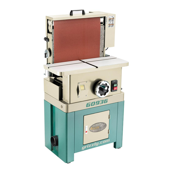
MODEL G0936
20" VERTICAL OSCILLATING
BELT SANDER
OWNER'S MANUAL
(For models manufactured since 06/21)
COPYRIGHT © NOVEMBER, 2021 BY GRIZZLY INDUSTRIAL, INC.
WARNING: NO PORTION OF THIS MANUAL MAY BE REPRODUCED IN ANY SHAPE
OR FORM WITHOUT THE WRITTEN APPROVAL OF GRIZZLY INDUSTRIAL, INC.
#CS21947 PRINTED IN TAIWAN
V1.11.21
Advertisement
Chapters
Table of Contents

Related Manuals for Grizzly G0936


Summary of Contents for Grizzly G0936
- Page 1 (For models manufactured since 06/21) COPYRIGHT © NOVEMBER, 2021 BY GRIZZLY INDUSTRIAL, INC. WARNING: NO PORTION OF THIS MANUAL MAY BE REPRODUCED IN ANY SHAPE OR FORM WITHOUT THE WRITTEN APPROVAL OF GRIZZLY INDUSTRIAL, INC. #CS21947 PRINTED IN TAIWAN V1.11.21...
- Page 2 This manual provides critical safety instructions on the proper setup, operation, maintenance, and service of this machine/tool. Save this document, refer to it often, and use it to instruct other operators. Failure to read, understand and follow the instructions in this manual may result in fire or serious personal injury—including amputation, electrocution, or death.
-
Page 3: Table Of Contents
Table of Contents INTRODUCTION ..........2 SECTION 5: ACCESSORIES ......24 Contact Info............ 2 SECTION 6: MAINTENANCE ......25 Manual Accuracy ........... 2 Schedule ............25 Identification ........... 3 Cleaning & Protecting ........25 Controls & Components ......... 4 Lubrication ........... 26 Machine Data Sheet ........ -
Page 4: Introduction
ID label (see below). This information is required for us to provide proper tech support, and it helps us determine if updated documentation is available for your machine. Manufacture Date Serial Number Model G0936 (Mfd. Since 06/21) -
Page 5: Identification
If normal safety pre- respect. Failure to do so could result in cautions are overlooked or ignored, seri- serious personal injury, damage to equip- ous personal injury may occur. ment, or poor work results. Model G0936 (Mfd. Since 06/21) -
Page 6: Controls & Components
Tighten to secure cover. Table: Supports workpiece against sanding belt and provides T-slot tracks for included miter gauge. Model G0936 (Mfd. Since 06/21) -
Page 7: Machine Data Sheet
MACHINE DATA SHEET Customer Service #: (570) 546-9663 · To Order Call: (800) 523-4777 · Fax #: (800) 438-5901 MODEL G0936 20" VERTICAL OSCILLATING BELT SANDER Product Dimensions: Weight................................362 lbs. Width (side-to-side) x Depth (front-to-back) x Height............31-1/2 x 27-1/2 x 54-1/2 in. - Page 8 The information contained herein is deemed accurate as of 12/1/2021 and represents our most recent product specifications. Model G0936 PAGE 2 OF 2 Due to our ongoing improvement efforts, this information may not accurately describe items previously purchased. Model G0936 (Mfd. Since 06/21)
-
Page 9: Section 1: Safety
Never operate under the influence of drugs or injury or blindness from flying particles. Everyday alcohol, when tired, or when distracted. eyeglasses are NOT approved safety glasses. Model G0936 (Mfd. Since 06/21) - Page 10 Make sure they are properly installed, you experience difficulties performing the intend- undamaged, and working correctly BEFORE ed operation, stop using the machine! Contact our operating machine. Technical Support at (570) 546-9663. Model G0936 (Mfd. Since 06/21)
-
Page 11: Additional Safety For Belt Sanders
To avoid these hazards, keep all control when sanding force is applied. guards in place and closed. DO NOT wear loose clothing, gloves, or jewelry, and tie back long hair. Model G0936 (Mfd. Since 06/21) -
Page 12: Section 2: Power Supply
To reduce the risk of these hazards, avoid over- loading the machine during operation and make sure it is connected to a power supply circuit that meets the specified circuit requirements. -10- Model G0936 (Mfd. Since 06/21) - Page 13 Minimum Gauge Size ......14 AWG all local codes and ordinances. Maximum Length (Shorter is Better)..50 ft. -11- Model G0936 (Mfd. Since 06/21)
-
Page 14: Section 3: Setup
IMPORTANT: Save all packaging materials until you are completely satisfied with the machine and have resolved any issues between Grizzly or the shipping agent. You MUST have the original pack- aging to file a freight claim. It is also extremely Wear safety glasses during helpful if you need to return your machine later. -
Page 15: Inventory
NOTICE Avoid harsh solvents like acetone or brake parts cleaner that may damage painted sur- faces. Always test on a small, inconspicu- ous location first. -13- Model G0936 (Mfd. Since 06/21) -
Page 16: Site Considerations
Only install in an Shadows, glare, or strobe effects that may distract access restricted location. or impede the operator must be eliminated. 31½" Electrical Connection 41½" Min. 30" for Maintenance Figure 6. Minimum working clearances. -14- Model G0936 (Mfd. Since 06/21) -
Page 17: Assembly
Install handwheel handle in handwheel, as Machine Base shown in Figure 8. Lag Shield Anchor Concrete Drilled Hole Figure 9. Popular method for anchoring machinery to a concrete floor. Handwheel Figure 8. Handwheel handle installed. -15- Model G0936 (Mfd. Since 06/21) -
Page 18: Dust Collection
Tug hose to make sure it does not come off. — If machine does not run smoothly, imme- diately turn machine OFF and call Tech Note: A tight fit is necessary for proper Support for help. performance. -16- Model G0936 (Mfd. Since 06/21) -
Page 19: Section 4: Operations
Regardless of the content in this sec- in this manual are easier to understand. tion, Grizzly Industrial will not be held liable for accidents caused by lack of training. Due to the generic nature of this overview, it is not intended to be an instructional guide. -
Page 20: Disabling & Locking Switch
The padlock shaft diameter is important to lifespan. the disabling function of the switch. With any padlock used to lock the switch, test the switch after installation to ensure that it is properly disabled. Figure 12. Minimum lock shaft requirements. -18- Model G0936 (Mfd. Since 06/21) -
Page 21: Sanding Tips
Always support workpiece against table and/or miter gauge when sanding. Use extreme care to provide safe distance between belt and any body part. -19- Model G0936 (Mfd. Since 06/21) -
Page 22: Installing/Changing Sanding Belt
Latch belt guard latch and tighten guard lock knob to secure latch. 10. Install belt cover and tighten (2) belt cover lock knobs to secure cover. 11. Install lock block and lock post thumb screw. -20- Model G0936 (Mfd. Since 06/21) -
Page 23: Tensioning Sanding Belt
Figure 17. Angle adjustment components. Turn belt tension handwheel (see Figure 16) to adjust belt tension. Tighten lock knob to secure setting. — Turn handwheel clockwise to tension belt. — Turn handwheel counterclockwise to detension belt. -21- Model G0936 (Mfd. Since 06/21) -
Page 24: Adjusting Platen Tilt
Measure gap between table and sanding belt (see Figure 18). — If gap is less than ⁄ ", no adjustment is required. ", proceed to Step 5. — If gap is more than ⁄ -22- Model G0936 (Mfd. Since 06/21) -
Page 25: Bevel Sanding
Maintain control of workpiece, as shown in Figure 22. DO NOT force workpiece against belt. Figure 20. Typical edge sanding operation. Figure 22. Typical bevel sanding operation. Figure 21. Typical end sanding operation. -23- Model G0936 (Mfd. Since 06/21) -
Page 26: Section 5: Accessories
" x 41 " Sanding Belts ⁄ ⁄ collection components for 4" dust ports. These tough, aluminum oxide sanding belts come in a variety of grits to fit the Model G0936. D4206 T33211—60-Grit, 1-Pk. T33212—80-Grit, 1-Pk. T33213—100-Grit, 1-Pk. T33214—120-Grit, 1-Pk. -
Page 27: Section 6: Maintenance
To reduce risk of shock or accidental startup, always disconnect machine from power before adjustments, Cleaning the Model G0936 is relatively easy. maintenance, or service. Vacuum excess sawdust, and wipe off the remain- ing dust with a dry cloth. If any resin has built up, use a resin dissolving cleaner to remove it. -
Page 28: Lubrication
Lubrication To lubricate leadscrew and trunnions: DISCONNECT MACHINE FROM POWER! Since all the bearings on the Model G0936 are Remove (4) Phillips head screws and flat sealed and permanently lubricated, simply leave washers shown in Figure 27 to remove pul- them until they need to be replaced. -
Page 29: Checking & Replacing V-Belt
To check and replace V-belt: V-belt from pulleys. DISCONNECT MACHINE FROM POWER! Place new belt around pulleys, then lower motor and close cabinet door. Install pulley cover. -27- Model G0936 (Mfd. Since 06/21) -
Page 30: Section 7: Service
7. Fix/replace fan cover; replace loose/damaged fan. 8. Centrifugal switch. 8. Adjust centrifugal switch. Replace if at fault. 9. Motor bearings at fault. 9. Test by rotating shaft; rotational grinding/loose shaft requires bearing replacement. -28- Model G0936 (Mfd. Since 06/21) -
Page 31: Dust Collection System
2. Sanding belt has been folded or crushed. Platen tilt 1. Platen angle leadscrew and trunnions 1. Clean and lubricate leadscrew and trunnions handwheel is clogged with sawdust/need lubrication. (Page 26). hard to rotate. -29- Model G0936 (Mfd. Since 06/21) -
Page 32: Adjusting Oscillation Timing & Speed
— If oscillation time to the left is longer than Items Needed to the right, tighten left limit switch screw Phillips Head Screwdriver #2 ......1 shown in Figure 35 until proper tracking is Open-End Wrench 8mm........1 achieved. -30- Model G0936 (Mfd. Since 06/21) -
Page 33: Squaring Platen To Table
90° Square ............1 Phillips Head Screwdriver #2 ......1 Hex Wrench 3mm ..........1 Open-End Wrench 29mm........1 Figure 37. Location of left side cover and To square platen to table: fasteners. DISCONNECT MACHINE FROM POWER! -31- Model G0936 (Mfd. Since 06/21) -
Page 34: Adjusting 45° Stop
0°, angle scale scale displays 45°, proceed to Step 5. needs to be calibrated (perform Steps 2–3 from Calibrating Platen Angle Scale on Page 33 before proceeding). Install back cover and left side cover. -32- Model G0936 (Mfd. Since 06/21) -
Page 35: Calibrating Platen Angle Scale
— If platen is 45° to table, but angle scale Install back cover and left side cover. does not display 45°, angle scale needs to be calibrated (perform Step 7 then refer to Calibrating Platen Angle Scale). Install pulley cover. -33- Model G0936 (Mfd. Since 06/21) -
Page 36: Calibrating Miter Gauge Scale
Step 3. Loosen set screw securing pointer, adjust pointer until it displays 90° when bar and body are square (see Figure 44), then tight- 45° Stop en set screw. Figure 45. Stop adjustment components. -34- Model G0936 (Mfd. Since 06/21) -
Page 37: Section 8: Wiring
Technical Support at (570) 546-9663. The photos and diagrams included in this section are best viewed in color. You can view these pages in color at www.grizzly.com. -35- Model G0936 (Mfd. Since 06/21) -
Page 38: Wiring Diagram
ON/OFF Switch KEDU HY56-4 Right KEDU HY50 Belt Tracking Limit Switches Ground KEDU Left HY50 Ground Run Capacitor 30uF 250V Start Capacitor 400MFD 125V 6-15 Plug Main Motor READ ELECTRICAL SAFETY -36- Model G0936 (Mfd. Since 06/21) ON PAGE 35! -
Page 39: Electrical Component Photos
Electrical Component Photos Figure 46. Oscillation limit switches. Figure 47. ON/OFF switch. Figure 48. Contactors. READ ELECTRICAL SAFETY -37- Model G0936 (Mfd. Since 06/21) ON PAGE 35! - Page 40 Figure 49. Oscillation motor junction box. Figure 52. Run capacitor. Figure 50. Main motor junction box. Figure 53. Left tracking limit switch. Figure 51. Start capacitor. Figure 54. Right tracking limit switch. READ ELECTRICAL SAFETY -38- Model G0936 (Mfd. Since 06/21) ON PAGE 35!
-
Page 41: Section 9: Parts
SECTION 9: PARTS We do our best to stock replacement parts when possible, but we cannot guarantee that all parts shown are available for purchase. Call (800) 523-4777 or visit www.grizzly.com/parts to check for availability. Cabinet 80-2 80-1 80-3 80-4... -
Page 42: Hose Clamp 4
MOTOR 2HP 220V 1-PH P0936119 FLAT WASHER 5/16 80-1 P0936080-1 MOTOR FAN COVER P0936143 LOCK WASHER 5MM 80-2 P0936080-2 MOTOR FAN BUY PARTS ONLINE AT GRIZZLY.COM! -40- Model G0936 (Mfd. Since 06/21) Scan QR code to visit our Parts Store. -
Page 43: Lower Roller
Lower Roller 328-1 328-2 BUY PARTS ONLINE AT GRIZZLY.COM! -41- Model G0936 (Mfd. Since 06/21) Scan QR code to visit our Parts Store. - Page 44 KEY 5 X 5 X 30 RE P0936372 FLAT HANDLE P0936277 STRAIN RELIEF TYPE-3 M20-1.5 P0936377 FLAT HD SCR M8-1.25 X 20 BUY PARTS ONLINE AT GRIZZLY.COM! -42- Model G0936 (Mfd. Since 06/21) Scan QR code to visit our Parts Store.
-
Page 45: Upper Roller
Upper Roller BUY PARTS ONLINE AT GRIZZLY.COM! -43- Model G0936 (Mfd. Since 06/21) Scan QR code to visit our Parts Store. - Page 46 P0936574 CAP SCREW M10-1.5 X 25 P0936503 SET SCREW 1/4-20 X 1/4 P0936575 LOCK WASHER 10MM P0936512 WORM SHAFT BUSHING (UPPER) BUY PARTS ONLINE AT GRIZZLY.COM! -44- Model G0936 (Mfd. Since 06/21) Scan QR code to visit our Parts Store.
-
Page 47: Electrical Box
Electrical Box BUY PARTS ONLINE AT GRIZZLY.COM! -45- Model G0936 (Mfd. Since 06/21) Scan QR code to visit our Parts Store. - Page 48 OSC LIMIT SWITCH (L) CORD 18G 2W 48" P0936742 CAP SCREW M5-.8 X 10 P0936776 OSC LIMIT SWITCH (R) CORD 16G 2W 9" P0936743 LOCK WASHER 5MM BUY PARTS ONLINE AT GRIZZLY.COM! -46- Model G0936 (Mfd. Since 06/21) Scan QR code to visit our Parts Store.
-
Page 49: Miter Gauge
SET SCREW 1/4-20 X 1/4 809 P0936809 PHLP HD SCR 8-32 X 3/4 805 P0936805 STOP LINK 810 P0936810 HEX NUT #8-32 BUY PARTS ONLINE AT GRIZZLY.COM! -47- Model G0936 (Mfd. Since 06/21) Scan QR code to visit our Parts Store. -
Page 50: Labels & Cosmetics
Safety labels help reduce the risk of serious injury caused by machine hazards. If any label comes off or becomes unreadable, the owner of this machine MUST replace it in the original location before resuming operations. For replacements, contact (800) 523-4777 or www.grizzly.com. BUY PARTS ONLINE AT GRIZZLY.COM! -48- Model G0936 (Mfd. -
Page 51: Warranty & Returns
WARRANTY & RETURNS Grizzly Industrial, Inc. warrants every product it sells for a period of 1 year to the original purchaser from the date of purchase. This warranty does not apply to defects due directly or indirectly to misuse, abuse, negligence, accidents, repairs or alterations or lack of maintenance.
Need help?
Do you have a question about the G0936 and is the answer not in the manual?
Questions and answers