
Related Manuals for MRC INE-DDBJ-350F


Summary of Contents for MRC INE-DDBJ-350F
- Page 1 INE-DDBJ-350F Portable Conductivity Meter Instruction Manual PLEASE READ THIS MANUAL CAREFULLY BEFORE OPERATION Hagavish st. Israel 58817 Tel: 972 3 5595252, Fax: 972 3 5594529 mrc@mrclab.com MRC.12.20...
- Page 2 TIPS Please read this instruction in detail before operating the meter. The meter must be sent to metrological service or other qualified departments to recheck after being used for one year, and only those qualified ones can be used again ...
-
Page 3: Table Of Contents
CONTENT 1. Installation 1.1 Unpacking 1.2 Structure 1.3 Installation 1.3.1 The installation of measuring probe 1.3.2 The installation of the power charger 1.3.3 The installation of the USB cable 1.3.4 Daily use 2. Operation 2.1 Introduction 2.1.1 Terms 2.1.2 Features 2.1.3 Technical specifications 2.1.4 Operation 2.1.5 Operation diagram... -
Page 4: Installation
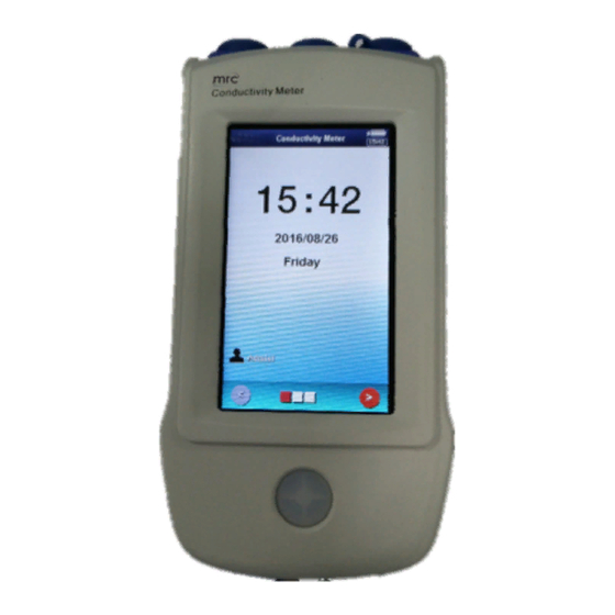
1 INSTALLATION 1.1 Unpacking In the packing box, users can find below parts: 1. INE-DDBJ-350F Portable conductivity meter 1set 2. Accessories 1set 1.2 Structure 1.2.1 Front view Front View Of The Meter (Figure1) The meter is composed of main unit and electrode system, both are indispensable. The meter supports conductive probe and ATC probe, allows the measurement of conductivity, TDS, resistivity, salinity value and temperature value. -
Page 5: Installation
2. The ATC probe 3. The charger 4. The USB cable 1.3 Installation Open the meter package, take out INE-DDBJ-350F portable conductivity meter and related accessories. 1.3.1 The installation of measuring electrode 1.3.1.1 The installation of conductive probe Find measuring electrode socket (8 pins) above the meter (Mini type socket, pay attention to the number of pins, don’t mistake with temperature... -
Page 6: Terms
2 When the meter is not used for a long time, the li-on may be low battery because of standing long time and unable operation, user need to connect the AC adapter and then switch on. 3 When connected to PC, the meter will automatically start charging function. 1.3.3 The installation of USB cable Users need to connect the USB cable if use our company's data acquisition software. -
Page 7: Features
2.1.2 Features INE-DDBJ-350F portable conductivity meter is a new design meter with following features: It adopts new microprocessor technology, 4.3 "TFT touch screen, reach 65k color gamut; It adopts li-on to stand long time for operation; It adopts new UI design specification, navigational operation and sliding operations;... -
Page 8: Operation
Resistivity: automatic grade; TDS: automatic grade; Salinity: 0.01%; Temperature: 0.1 . 3. Error of the meter Conductivity: ±1.0%FS; Resistivity: ±1.0%FS; TDS: ±1.0%FS; Salinity: ±0.2%; Temperature: ±0.2 . 4. Normal operating conditions: ... -
Page 9: Measurement Parameters
2.1.5 Operation chart Power on, self-test Enter into the initial interface. The initial interface has three parts: Basic information, measuring signal monitoring, system System menu Basic information Measuring signal System Display monitoring settings Shows current current time ... - Page 10 Reading method: it is the reading method of current measurement parameters. The meter supports three reading methods, continuous reading method, smart reading methods and timed reading method. Continuous reading method: This reading method is suitable for continuous monitoring of the sample data, observing the change trend of sample.
- Page 11 Set Cell constant, this parameter is corresponding to conductivity and salinity measurement parameters. Usually there are two ways to get Cell constant: Calibrate the conductive probe with standard conductivity solution, or set the Cell constant value directly. Set TDS factor, this parameter is corresponding to the TDS measurements. Usually there are two ways to get TDS : Calibrate the conductive probe with standard conductivity solution, or set the TDS factor directly .
-
Page 12: Start-Up, Shutdown And Buttons
Sample ID, its the name of the sample, maximum 10 characters. Alarm switch, the meter supports alarm function. When the measured value exceeds the alarm value, the meter will alert to remind users, the default display numbers turn to yellow. If user doesn’t need this function, close the alarm switch. ... - Page 13 Measuring signal monitoring interface displays the current measurement signal and the last conductive probe calibration results; Click measurement window can start formal measurement, click the ">" button on the right to switch to view other parameters; Click ">" button in the last correction result window to calibrate electrode directly .
-
Page 14: System Setup
2.5 Operation 2.5.1 System settings System settings includes function modules, such as system time, buzzer, automatic backlight, automatic shutdown, user ID management, touch screen, language selection, about, etc. In the initial state, select menu item "System Settings" to enter, as shown in figure 7. System Setup Diagram (Figure 7) ... -
Page 15: Conductive Probe Calibration
Brightness control is for the purpose of saving power consumption, the meter also allows user to set the brightness of the backlight. The higher brightness, the greater the power consumption, but showed the best effect. Automatic shutdown: The meter has automatic shutdown function. There are ten options: off, 1 min, 2 min, 3 min, 5 min, 10 min, 15 min, 20 min, 30 min, 60 min;... -
Page 16: Before Calibration
in figure. If user wants to restart correction, choose to delete, or else choose to keep. For example, the last calibration use 146μS/cm and 1408μS/cm to complete two point correction, but user only wants to re-calibrate point 1408μS/cm, then can choose to keep current calibration data. Keep Last Calib Data Diagram (Figure 8) The meter adopts the navigational direction calibration, users complete the correction in accordance with the instructions step by step. - Page 17 Relation of KCl solution concentration and conductivity value (unit:μS/cm) Temp 15.0 18.0 20.0 25.0 35.0 Concentration (mol/L) 92120 97800 101700 111310 131100 10455 11163 11644 12852 15353 0.01 1141.4 1220.0 1273.7 1408.3 1687.6 0.001 118.5 126.7 132.2 146.5 176.5 The composition of standard solution Concentration Volume concentration KCl(g/L)solution (20 in air) (mol/L)
-
Page 18: Check Calibration Parameters
2.6.3 Check calibration parameters The meter supports automatic identification function of the conductivity solution, the default four JJG standard solution, standard data using potassium chloride solution, nominal concentration respectively is 1 mol/L , 0.1 mol/L, 0.01 mol/L, 0.001 mol/L. If user adopts non-standard solution for the meter, set the recognition type as "Manual identification", and manually enter the nominal value. -
Page 19: Calibration Results Report
"Calibrate" button to complete the correction. The meter supports repeating calibrate of the same standard solution, that is support the function of matching the same solution, if the current correction solution differ 50uS/cm with previous standard solution, the meter consider to be the same solution, will automatically cover the calibration data of previous standard solution. -
Page 20: Measurement
Calibration Result Diagram (Figure 12) Measurement 2.7.1 Preparation Before measurement, user should understand better the nature and character of measured sample; the basic operation and application of the meter; understand the use and maintenance of conventional electrodes. To prepare conductive probe before measurement, if need calibration, then purchase or self prepare. -
Page 21: Check Measurement Parameters
adsorbed sample components, must be washed after measurement. Placed in a period of time or use after period of time, the constant of conductive probe may change and need to be re-calibrated. The meter provides two ways to start measurement. One is to Start measurement according to the last configuration, the other is to view or modify before measurement. -
Page 22: Check Reading Mode
Check Measurement Parameter Diagram (Figure 14) 2.7.3 Check reading mode Check Reading Mode Diagram (Figure 15) The navigation page includes the current measuring parameters, reading method, conductivity compensation method, conductivity reference temperature, data stability condition, etc., related parameters varies with reading method, shown in Figure 15. -
Page 23: Check Calibration Result
2.7.4 Check calibration result This navigation page shows the last conductive probe calibration result, this data is also the electrode parameters to be used in current measurement. If user needs to re-calibrate, then double-click the last calibration results data area, confirm to the re-calibrate probes, the meter guide the user to complete calibration, detailed calibration please refer to electrode adjustment section, as shown in Figure 16. -
Page 24: Check Temperature Options
2.7.5 Check temperature options This navigation page sets temperature display type, temperature compensation method. Check Temp Option diagram (Figure 17) 2.7.6 Check sample, alarm setting This navigation page sets measuring sample alarm option. If necessary, set the alarm switch, high limit alarm and low limit alarm, when measuring results exceeded the set alarm value, the meter will express with visible mark, yellow digital display in order to prompt the user by default, as shown in Figure 18. -
Page 25: Start Measurement
2.7.7 Start measurement After all of the above operation is completed, click on "Next" to start formal measurement, display as shown in figure 19. Measurement Display Diagram (Figure 19) In the figure, above is the measurement window, also shows the results of the measuring parameters and measuring results of related auxiliary parameters. -
Page 26: End Measuring, Result Report
When the reading mode is continuous measurement mode, the meter always monitoring the whole measurement process, until user manually end the measurement. The meter allows users to store measurement results manually. During the measurement process, press the "End" key to terminate at any time. 2.7.8 End measuring, result report When the measuring is finished or terminated, the meter provides a simple... -
Page 27: View Stored Result
Check Calibration Data Diagram (Figure 21) 2.8.2 View stored result In the initial state, click the menu item "View stored results" to enter. 2.8.2.1 View settings The meter supports multiple view modes, view stored data according to store numbers and storage time. User sets view modes according to the actual needs, then press "Start search";... -
Page 28: View Result
2.8.2.2 View result The meter shows the matching results that meet the consulting conditions in curve, shown in figure. The figure includes view content, current view method, view scope, the number of matching results, the beginning number of current curve, the end number of current curve, etc. Buttons are show on the right side of the curve. - Page 29 Result Report Diagram (Figure 24)
-
Page 30: Maintenance
Product ordering information Product name and type Specifications A new generation of conductivity meter, meet the measurement INE-DDBJ-350F Portable requirements of portable conductivity, TDS, salinity, resistivity, Conductivity Meter temperature, measuring range: 1.0 grade, measurement range: 0.000 mu S/cm ~ 1000 ms/cm; Accuracy: ± 1.0% (FS);... - Page 31 Packing List INE-DDBJ-350F Portable Conductivity Meter Number Description Quantity INE-DDBJ-350F Portable Conductivity Meter DJS-1-L Conductive probe T-818-L ATC probe USB Power Supply(5V/1A) Mini USB Line Stylus Manual...
Need help?
Do you have a question about the INE-DDBJ-350F and is the answer not in the manual?
Questions and answers