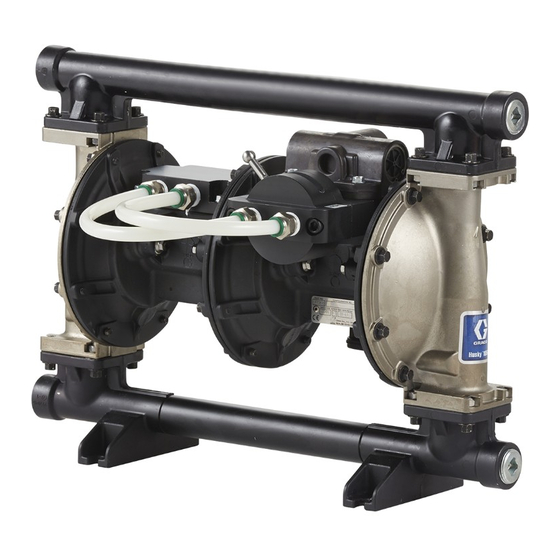
Graco Husky 1050HP Repair Parts
2:1 air-operated diaphragm pump
Hide thumbs
Also See for Husky 1050HP:
- Repair parts (48 pages) ,
- Operation (22 pages) ,
- Repair parts (46 pages)
Table of Contents
Advertisement
Quick Links
Repair/Parts
Husky™ 1050HP
1050HP 2:1
Husky™
Husky™
1050HP
Air
Air
Air - - - Operated
Operated Diaphragm
Operated
1 1 1 - - - inch
inch high
inch
high- - - pressure
high
pressure
pressure pump
pump
pump with
only.
only.
only.
Important
Important Safety
Important
Safety Instructions
Safety
Read all warnings and instructions in this manual and in your
Operation manual. Save
Maximum Fluid Working Pressure:
250 psi (1.72 MPa, 17.2 bar)
Maximum Air Input Pressure: 125 psi
(0.86 MPa, 8.6 bar)
See page 4 for approvals.
All manuals and user guides at all-guides.com
2:1
2:1
Diaphragm Pump
Diaphragm
with modular
with
modular air
modular
air
air valve
valve
valve for
Instructions
Instructions
Save
Save these
these instructions.
these
instructions.
instructions.
PROVEN QUALITY. LEADING TECHNOLOGY.
Pump
Pump
for fluid
for
fluid transfer
fluid
transfer applications.
transfer
applications. For
applications.
334390E
EN
For professional
For
professional use
professional
use
use
Advertisement
Table of Contents

Related Manuals for Graco Husky 1050HP


Summary of Contents for Graco Husky 1050HP
- Page 1 All manuals and user guides at all-guides.com Repair/Parts Husky™ 1050HP 1050HP 2:1 Husky™ Husky™ 1050HP 334390E Air - - - Operated Operated Diaphragm Operated Diaphragm Diaphragm Pump Pump Pump 1 1 1 - - - inch inch high inch high- - - pressure high pressure pressure pump...
-
Page 2: Table Of Contents
Replace Seals or Rebuild Air Valve ....12 Replace Complete High/Low Valve ....14 Graco Standard Husky Pump Warranty....46 Related Related Related Manuals Manuals Manuals Manual Manual Manual No. Description Description Description 334014 Husky 1050HP 2:1 Air-Operated Diaphragm Pump, Operation 334390E... -
Page 3: Ordering Information
Please Please Please call call call your your distributor. your distributor. distributor. ordering information, as needed. 2. Please call Graco Customer Service to order. To Order Order Order Replacement Replacement Parts Replacement Parts Parts Please Please Please call... -
Page 4: Configuration Number Matrix
All manuals and user guides at all-guides.com Configuration Number Matrix Configuration Number Number Matrix Matrix Configuration Configuration Number Matrix Check the identification plate (ID) for the 20–digit Configuration Number of your pump. Use the following matrix to define the components of your pump. -
Page 5: Warnings
All manuals and user guides at all-guides.com Warnings Warnings Warnings Warnings The following warnings are for the setup, use, grounding, maintenance, and repair of this equipment. The exclamation point symbol alerts you to a general warning and the hazard symbols refer to procedure-specific risks. - Page 6 All manuals and user guides at all-guides.com Warnings WARNING WARNING WARNING EQUIPMENT MISUSE MISUSE HAZARD HAZARD EQUIPMENT EQUIPMENT MISUSE HAZARD Misuse can cause death or serious injury. • Do not operate the unit when fatigued or under the influence of drugs or alcohol. •...
- Page 7 All manuals and user guides at all-guides.com Warnings WARNING WARNING WARNING PLASTIC PARTS PARTS CLEANING CLEANING SOLVENT SOLVENT HAZARD HAZARD PLASTIC PLASTIC PARTS CLEANING SOLVENT HAZARD Many solvents can degrade plastic parts and cause them to fail, which could cause serious injury or property damage.
-
Page 8: Troubleshooting
All manuals and user guides at all-guides.com Troubleshooting Troubleshooting Troubleshooting Troubleshooting Problem Problem Problem Cause Cause Cause Solution Solution Solution Pump cycles but will not prime. Pump is running too fast, causing Reduce air inlet pressure. cavitation before prime. Check valve ball severely worn or Replace ball and seat. - Page 9 All manuals and user guides at all-guides.com Troubleshooting Problem Cause Solution Problem Problem Cause Cause Solution Solution Air bubbles in fluid. Suction line is loose. Tighten. Diaphragm ruptured. Replace. Loose manifolds, damaged seats or Tighten manifold bolts or replace o-rings. seats or o-rings.
-
Page 10: Repair
All manuals and user guides at all-guides.com Repair Repair Repair Repair Pressure Relief Relief Procedure Procedure Replace Complete Complete Air Air Valve Valve Pressure Pressure Relief Procedure Replace Replace Complete Valve Follow the Pressure Relief Procedure Follow these instructions to install Air Valve whenever you see this symbol. - Page 11 All manuals and user guides at all-guides.com Repair Apply thread lubricant to threads before assembly. Torque screws to 80 in-lb (9 N•m). 334390E...
-
Page 12: Replace Seals Or Rebuild Air Valve
Reassemble Reassemble the the Air Air Valve Valve Valve housing. NOTE: NOTE: NOTE: Apply lithium-based grease when instructed 6. Install a retaining ring (310‡) on each end to hold to grease. Order Graco PN 111920. end caps in place. 334390E... - Page 13 All manuals and user guides at all-guides.com Repair 7. Grease and install the detent assembly (303♦) into the piston. Install the o-ring (314♦) on the cup (313♦). Apply a light film of grease to the outside surface of the o-ring and the inside mating surface of the base (312♦).
-
Page 14: Replace Complete High/Low Valve
All manuals and user guides at all-guides.com Repair Replace Complete Complete High/Low High/Low Valve Valve Replace Replace Complete High/Low Valve 1. Stop the pump. Follow the Pressure Relief Procedure, page 2. Disconnect the main air line. Release the quick disconnect fittings to remove the air manifold hoses (108). -
Page 15: Valve
All manuals and user guides at all-guides.com Repair Replace Seals Seals or or or Rebuild Rebuild the the High/Low High/Low Valve Valve Replace Replace Seals Rebuild High/Low Valve Follow these instructions to service the High/Low 3. Grease and install three o-rings (402 and 405) valve. -
Page 16: Check Valve Repair
All manuals and user guides at all-guides.com Repair Check Valve Valve Repair Repair Check Check Valve Repair NOTE: Kits are available for new check valve balls NOTE: NOTE: and seats. See Seats and Check Balls to order kits in the material(s) desired. O-ring and fastener kits also are available. -
Page 17: Diaphragm And Center Section Repair
All manuals and user guides at all-guides.com Repair Diaphragm and and Center Center Section Section Repair Repair Diaphragm Diaphragm Center Section Repair Disassemble the the Center Center Section Section Disassemble Disassemble Center Section 1. Use a 10 mm socket wrench to remove the screws (5), then separate the primary air module (101) from the secondary air module (102). - Page 18 All manuals and user guides at all-guides.com Repair Reassemble the the Center Center Section Section Reassemble Reassemble Center Section 3. Grease and install the pilot valves (205*, primary side) or secondary pilot plugs (220*, secondary side). Torque to 20–25 in-lb (2–3 N•m) at 100 Follow all notes in the illustrations.
- Page 19 All manuals and user guides at all-guides.com Repair Primary Primary Primary Air Air Module Module Module Secondary Air Air Module Module Secondary Secondary Module Apply lithium based grease. Lips must face out of housing. Cartridges (204) must be installed before pilot valves (205) or secondary pilot plugs (220). Torque to 20-25 in.-lb (2-3 N•m).
- Page 20 All manuals and user guides at all-guides.com Repair Reassemble the the Fluid Fluid Diaphragms Diaphragms Reassemble Reassemble Fluid Diaphragms Follow all notes in the illustrations. These notes 1. Assemble the center diaphragm section: contain important important information. important a. Assemble the primary side air plate (105*), NOTE: Apply lithium-based grease whenever NOTE: NOTE:...
- Page 21 All manuals and user guides at all-guides.com Repair 2. Grease the shaft u-cups (202*) and the length of 5. Bolt-Through Bolt-Through Diaphragms Bolt-Through Diaphragms Diaphragms both diaphragm shafts (206*). Slide the shaft on a. Assemble the o-ring (28), the fluid side the primary side (closest to air plate 105*) into diaphragm plate (10), the diaphragm (12), the primary air module.
- Page 22 All manuals and user guides at all-guides.com Repair 6. Overmolded Overmolded Overmolded Diaphragms Diaphragms Diaphragms a. If the diaphragm setscrew comes loose or is replaced, apply permanent (red) thread sealant to the diaphragm-side threads. Screw into the diaphragm until tight. b.
- Page 23 All manuals and user guides at all-guides.com Repair 7. Reattach the secondary side fluid cover (2). 8. To ensure proper seating and extend diaphragm The arrow must point toward the air valve. See life, apply air pressure to the pump prior to Torque Instructions, page attaching the fluid cover on the primary air module.
-
Page 24: Torque Instructions
All manuals and user guides at all-guides.com Torque Instructions Torque Torque Torque Instructions Instructions Instructions NOTE: All fasteners for the fluid covers, center Fluid cover, cover, center center diaphragm diaphragm joint, joint, and and manifold manifold NOTE: NOTE: Fluid Fluid cover, center diaphragm... -
Page 25: Notes
All manuals and user guides at all-guides.com Notes Notes Notes Notes 334390E... -
Page 26: Parts
All manuals and user guides at all-guides.com Parts Parts Parts Parts 334390E... - Page 27 All manuals and user guides at all-guides.com Parts Parts/Kits Quick Quick Reference Reference Parts/Kits Parts/Kits Quick Reference Use this table as a quick reference for parts/kits. Go to the pages indicated in the table for a full description of kit contents. Description Qty.
- Page 28 All manuals and user guides at all-guides.com Parts Center Section Section Center Center Section Sample Configuration Configuration Number Number Sample Sample Configuration Number Pump Pump Pump Center Center Center Fluid Fluid Fluid Seats Seats Seats Balls Balls Balls Diaphragms Diaphragms Diaphragms Seat Seat and...
- Page 29 All manuals and user guides at all-guides.com Parts Notes Notes Notes 334390E...
- Page 30 All manuals and user guides at all-guides.com Parts Primary Primary Primary Air Air Module Module Module Sample Sample Sample Configuration Configuration Configuration Number Number Number Pump Center Fluid Seats Balls Diaphragms Seat and Pump Pump Center Center Fluid Fluid Seats Seats Balls Balls...
- Page 31 All manuals and user guides at all-guides.com Parts Description Description Description Description Description Description HOUSING, center, not sold O-RING, Buna-N, 1.125 in. (29 mm) see page 37 separately 202* U-CUP, center shaft VALVE, High/Low, see page 38 VALVE, air, see page 37 203* BEARING, center shaft 204*...
- Page 32 All manuals and user guides at all-guides.com Parts Secondary Air Air Module Module Secondary Secondary Module Sample Configuration Configuration Number Number Sample Sample Configuration Number Pump Pump Pump Center Center Center Fluid Fluid Fluid Seats Seats Seats Balls Balls Balls Diaphragms Diaphragms Diaphragms...
- Page 33 All manuals and user guides at all-guides.com Parts Description Description Description Description Description Description HOUSING, center, not sold 213* GASKET, air valve separately PLUG, pipe, order PN 102726 202* U-CUP, center shaft 217* SCREW, M6 x 25, thread forming 203* BEARING, center shaft 219* O-RING, receiver cartridge, Buna-N,...
- Page 34 All manuals and user guides at all-guides.com Parts Center Section Section Kits Kits Center Center Section Kits Sample Configuration Number Pump Center Fluid Seats Balls Diaphragms Seat and Model Covers and Section and Manifold Manifolds Air Valve Seal 1050HP A01A A01A A01A Center Section...
- Page 35 All manuals and user guides at all-guides.com Parts Air Valve Valve Valve Sample Configuration Configuration Number Number Sample Sample Configuration Number Pump Pump Pump Center Center Center Fluid Fluid Fluid Seats Seats Seats Balls Balls Balls Diaphragms Diaphragms Diaphragms Seat Seat and Seat Model...
- Page 36 All manuals and user guides at all-guides.com Parts Description Description Description Description Description Description HOUSING, not sold 308F= U-CUP, carboxylated nitrile separately 309F= SCREW, M3, thread forming 302F PISTON 310‡ RETAINING RING 303F PISTON ASSEMBLY, detent 311F SPRING, detent 304F CAM, detent 312F BASE, cup...
- Page 37 All manuals and user guides at all-guides.com Parts Sample Configuration Number Pump Center Fluid Seats Balls Diaphragms Seat and Model Section and Covers and Manifold Manifolds Air Valve Seal 1050HP A01A A01A A01A = = = Air Air Valve Valve Seals Seals Kit Kit 24K859 24K859...
- Page 38 All manuals and user guides at all-guides.com Parts High/Low High/Low High/Low Valve Valve Valve Sample Configuration Configuration Number Number Sample Sample Configuration Number Pump Pump Pump Center Center Center Fluid Fluid Fluid Seats Seats Seats Balls Balls Balls Diaphragms Diaphragms Diaphragms Seat Seat and...
- Page 39 All manuals and user guides at all-guides.com Parts Fluid Covers Covers and and Manifolds Manifolds Fluid Fluid Covers Manifolds Sample Sample Sample Configuration Configuration Configuration Number Number Number Pump Pump Pump Center Fluid Fluid Fluid Seats Balls Balls Balls Diaphragms Diaphragms Diaphragms Seat and...
- Page 40 All manuals and user guides at all-guides.com Parts Seats and and Check Check Balls Balls Seats Seats Check Balls Sample Sample Sample Configuration Configuration Configuration Number Number Number Pump Pump Pump Center Fluid Fluid Fluid Seats Balls Balls Balls Diaphragms Diaphragms Diaphragms Seat and...
- Page 41 All manuals and user guides at all-guides.com Parts Diaphragms Diaphragms Diaphragms Sample Configuration Configuration Number Number Sample Sample Configuration Number Pump Pump Pump Center Center Center Fluid Fluid Fluid Seats Seats Seats Balls Balls Balls Diaphragms Diaphragms Diaphragms Seat Seat and Seat Model Model...
- Page 42 All manuals and user guides at all-guides.com Parts Aluminum Manifold Manifold Pumps: Pumps: Aluminum Aluminum Manifold Pumps: Overmolded Diaphragm Diaphragm Kits Kits Overmolded Overmolded Diaphragm Kits 24B625 Air and and Fluid Fluid Fluid Plate Plate Kit Plate Kit 24C035 24C035 24C035 Kit includes: Kit includes:...
- Page 43 All manuals and user guides at all-guides.com Parts Manifold Seals Seals Manifold Manifold Seals Sample Sample Sample Configuration Configuration Configuration Number Number Number Pump Pump Pump Center Fluid Fluid Fluid Seats Balls Balls Balls Diaphragms Diaphragms Diaphragms Seat and Center Center Seats Seats...
-
Page 44: Technical Data
All manuals and user guides at all-guides.com Technical Data Technical Technical Technical Data Data Data Metric Metric Metric Maximum Maximum fluid Maximum fluid fluid working working pressure working pressure pressure 250 psi 1.72 MPa,17.2 bar Air pressure pressure pressure operating operating range operating range... -
Page 45: Fluid Temperature Range
All manuals and user guides at all-guides.com Fluid Temperature Range Sound Power Power (measured per ISO-9614–2) Sound Sound Power At 70 psi (0.48 MPa, 4.8 bar) and 50 cpm Low Pressure Setting 78 dBa High Pressure Setting 91 dBa At 100 psi (0.7 MPa, 7.0 bar) and full flow Low Pressure Setting 90 dBa High Pressure Setting... -
Page 46: Graco Standard Husky Pump Warranty
Graco to be defective. This warranty applies only when the equipment is installed, operated and maintained in accordance with Graco’s written recommendations. This warranty does not cover, and Graco shall not be liable for general wear and tear, or any malfunction, damage or wear caused by faulty installation, misapplication, abrasion, corrosion, inadequate or improper maintenance, negligence, accident, tampering, or substitution of non-Graco component parts.