Table of Contents
Advertisement
Quick Links
ON/OFF BUTTON
USED TO TURN
DEHUMIDIFIER ON
CHANGE HUMIDITY
AND OFF
MODE BUTTON
USED FOR OPTIONAL
VENTILATION FEATURE
90-1853
TABLE OF CONTENTS
SAFETY INSTRUCTIONS . . . . . . . . . . . . . . . . . . . . . . . . . . . . . . . . . . . . . . . . . . 2
SPECIFICATIONS . . . . . . . . . . . . . . . . . . . . . . . . . . . . . . . . . . . . . . . . . . . . . . . . . 3
SET UP DEHUMIDIFIER FOR INSTALLATION . . . . . . . . . . . . . . . . . . . . . . . . 4
Packaging Content . . . . . . . . . . . . . . . . . . . . . . . . . . . . . . . . . . . . . . . . . . . . . 4
Duct Collars . . . . . . . . . . . . . . . . . . . . . . . . . . . . . . . . . . . . . . . . . . . . . . . . . . . . 4
Control Location . . . . . . . . . . . . . . . . . . . . . . . . . . . . . . . . . . . . . . . . . . . . . . . . 5
LOCATION CONSIDERATIONS . . . . . . . . . . . . . . . . . . . . . . . . . . . . . . . . . . . . . 5
DRAIN INSTALLATION . . . . . . . . . . . . . . . . . . . . . . . . . . . . . . . . . . . . . . . . . . . . 6
Leveling . . . . . . . . . . . . . . . . . . . . . . . . . . . . . . . . . . . . . . . . . . . . . . . . . . . . . . . 7
Condensate Pan, Condensate Pump and Float Switch . . . . . . . . . . . . . . 7
MODEL A77 - REMOTE CONTROL AND WIRING . . . . . . . . . . . . . . . . . . . . 8
Alternate External Controls . . . . . . . . . . . . . . . . . . . . . . . . . . . . . . . . . . . . . . 8
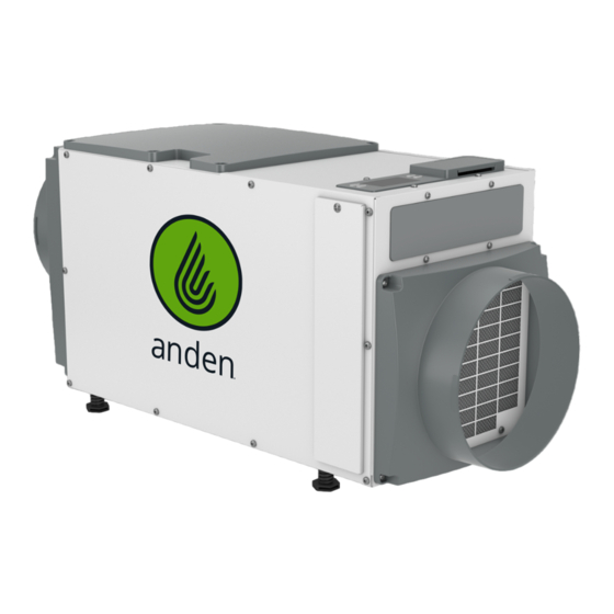
Model A100 Dehumidifier
Installation and Operating Instructions
UP/DOWN
BUTTONS USED TO
SETTING
INLET
READ AND SAVE THESE INSTRUCTIONS
DEHUMIDIFIER CONTROL
FILTER
DRAIN
ACCESS DOOR
SYSTEM SET UP & CHECKOUT . . . . . . . . . . . . . . . . . . . . . . . . . . . . . . . . . . . . . 9
Installer Test Mode . . . . . . . . . . . . . . . . . . . . . . . . . . . . . . . . . . . . . . . . . . . . . 10
START UP AND SEQUENCE OF OPERATION . . . . . . . . . . . . . . . . . . . . . . . . 11
Using the Dehumidifier Control . . . . . . . . . . . . . . . . . . . . . . . . . . . . . . . . . . 11
Using Model A77 Remote Control . . . . . . . . . . . . . . . . . . . . . . . . . . . . . . . . 11
MAINTENANCE . . . . . . . . . . . . . . . . . . . . . . . . . . . . . . . . . . . . . . . . . . . . . . . . . . . 11
Clean or Replace the Filter . . . . . . . . . . . . . . . . . . . . . . . . . . . . . . . . . . . . . . 11
Drain and Drain Insert Inspection . . . . . . . . . . . . . . . . . . . . . . . . . . . . . . . . 12
Removing and Reinstalling the Drain Insert . . . . . . . . . . . . . . . . . . . . . . 12
TROUBLESHOOTING . . . . . . . . . . . . . . . . . . . . . . . . . . . . . . . . . . . . . . . . . . . . 13
Table 2 - Diagnostic Codes . . . . . . . . . . . . . . . . . . . . . . . . . . . . . . . . . . . . . 13
Table 3 - Troubleshooting Guide . . . . . . . . . . . . . . . . . . . . . . . . . . . . . . . . 14
SERVICE PARTS . . . . . . . . . . . . . . . . . . . . . . . . . . . . . . . . . . . . . . . . . . . . . . . . . 15
LIMITED WARRANTY . . . . . . . . . . . . . . . . . . . . . . . . . . . . . . . . . . . . . . . . . . . . 16
OUTLET
POWER
SWITCH
Advertisement
Table of Contents

Related Manuals for Anden A100


Summary of Contents for Anden A100
-
Page 1: Table Of Contents
Model A100 Dehumidifier Installation and Operating Instructions ON/OFF BUTTON UP/DOWN DEHUMIDIFIER CONTROL OUTLET USED TO TURN BUTTONS USED TO DEHUMIDIFIER ON CHANGE HUMIDITY AND OFF SETTING MODE BUTTON USED FOR OPTIONAL VENTILATION FEATURE 90-1853 INLET FILTER DRAIN POWER ACCESS DOOR... -
Page 2: Safety Instructions
SAFETY INSTRUCTIONS WARNING 1. 120 Volts may cause serious injury from electric shock. Disconnect electrical power before starting installation or servicing. Leave power disconnected until installation/service is completed. 2. Sharp edges may cause serious injury from cuts. Use care when cutting plenum openings and handling duct work. 3. -
Page 3: Specifications
SPECIFICATIONS Model A100 TABLE 1 – SPECIFICATIONS Unit Weight 64 lbs Shipping Weight 82 lbs Capacity (AHAM DH-1-2008 80°F, 60% RH) 100 pints per day @ 280 CFM Efficiency 2 . 6 L/kW-hr (5 . 7 pints/kW-hr) @ 80°F, 60% RH Power (115 VAC, Single Phase, 60Hz) 6 . -
Page 4: Set Up Dehumidifier For Installation
SET UP DEHUMIDIFIER FOR INSTALLATION IMPORTANT: Cut the strap securing the compressor shipping support bracket and remove the strap and shipping bracket . See FIGURE 1 . FIGURE 1 – REMOVE SHIPPING BRACKET PACKAGING CONTENT REMOVE SHIPPING BRACKET 1. Dehumidifier 2. -
Page 5: Control Location
CONTROL LOCATION The on-board control can be located on the top of the dehumidifier or can be relocated to the front of the FIGURE 5 – CONTROL LOCATION dehumidifier if the control cannot be seen/accessed in CONTROL PANEL COVER the top orientation . It may also be rotated 180 degrees CONTROL in either orientation as shown in FIGURE 6 . -
Page 6: Drain Installation
DRAIN INSTALLATION The drain outlet on the dehumidifier can be hard piped using a 3/4" PVC Slip x 3/4" MNPT fitting and 3/4" nominal drain tubing or the provided 3/4" MNPT x 3/4" hose barb fitting . 3/4" clear PVC tubing can be used to drain the dehumidifier . Always maintain a constant downward slope from the dehumidifier to the drain and do not allow soft tubing to curl up which may result in air lock . -
Page 7: Leveling
LEVELING The feet can be adjusted to level the unit and accommodate drain fittings and secondary condensate FIGURE 8 – LEVEL THE UNIT BUBBLE LEVEL pans as required . Refer to top mounted bubble level and adjust feet until bubble is within the outer circle . Leveling is required to ensure proper drainage from the dehumidifier . -
Page 8: Model A77 - Remote Control And Wiring
MODEL A77 – REMOTE CONTROL AND WIRING NOTE: Use 18-22 AWG wire for control wiring . FIGURE 10 – MODEL A77 REMOTE CONTROL WIRING Humidity can be controlled using the internal dehumidifier control, a Model A77 control or a different external control like a thermostat . Installing an external control eliminates the need to run the dehumidifier blower for sampling as the control is constantly measuring the humidity close to the canopy . -
Page 9: System Set Up & Checkout
SYSTEM SET-UP & CHECKOUT Skip set up and proceed to INSTALLER TEST MODE on page 10 unless: REMOTE CONTROL • A Model A77 or other external control is to be installed If not installing an A77, leave • changing the air sampling rate DISABLED and press MODE to go 1. -
Page 10: Installer Test Mode
AIR SAMPLING INSTALLER TEST MODE Use the UP or DOWN button to If everything is properly wired, the dehumidifier and all of the adjust how frequently the wired components will turn on and off during Installer Test dehumidifier samples the air to Mode to demonstrate that all are properly operating . -
Page 11: Start Up And Sequence Of Operation
START UP AND SEQUENCE OF OPERATION USING THE DEHUMIDIFIER CONTROL 1. Press the ON/OFF button to turn the dehumidifier control ON . The display will show the current setting, and the dehumidifier blower will turn on to start sampling the air . The setting will be replaced by the measured humidity and “AIR SAMPLING”... -
Page 12: Drain And Drain Insert Inspection
DRAIN AND DRAIN INSERT INSPECTION The drain and drain insert should be checked annually to ensure there are no blockages or air lock in the drain system . IMPORTANT The drain insert is a critical feature of the dehumidifier drain management system. This component is required for the dehumidifier to run properly. -
Page 13: Troubleshooting
TROUBLESHOOTING Technical Support is available Monday through Friday, 7:00 a . m . to 5:00 p . m . CST, at (800) 972-3710 . Use the guides on the following pages to identify and correct system faults . Contact Technical Support before replacing the unit or any components and for additional troubleshooting . DIAGNOSTIC CODES When an error occurs, the Diagnostic Code along with SERVICE REQUIRED will be displayed on the control screen . - Page 14 TABLE 3 – TROUBLESHOOTING GUIDE Symptom Possible Reason Troubleshooting Procedure Dehumidifier does not No power to unit . • Check that the dehumidifier is plugged in . turn on/run . • Check that the power switch is turned ON . •...
-
Page 15: Service Parts
SERVICE PARTS 90-2595 Part Description Part No. Part Description Part No. Filter, 11 . 8 8" x 13 . 5 " x 1", MERV 11 5895 Wire Harness, Power, Deh 5884 Internal Control Board, Deh 5444 Sensor, Low Temperature, Deh 5455 User Interface Assembly, Deh 5738... -
Page 16: Limited Warranty
WARRANTY REGISTRATION Visit us online at anden.com to register your Anden product . If you do not have online access, please mail a postcard with your name, address, phone number, email address, product purchased, model number, date of purchase, and dealer name and address to: Research Products Corporation, P .
Need help?
Do you have a question about the A100 and is the answer not in the manual?
Questions and answers