
Related Manuals for Johnson Controls York YCRL0200HE


Summary of Contents for Johnson Controls York YCRL0200HE
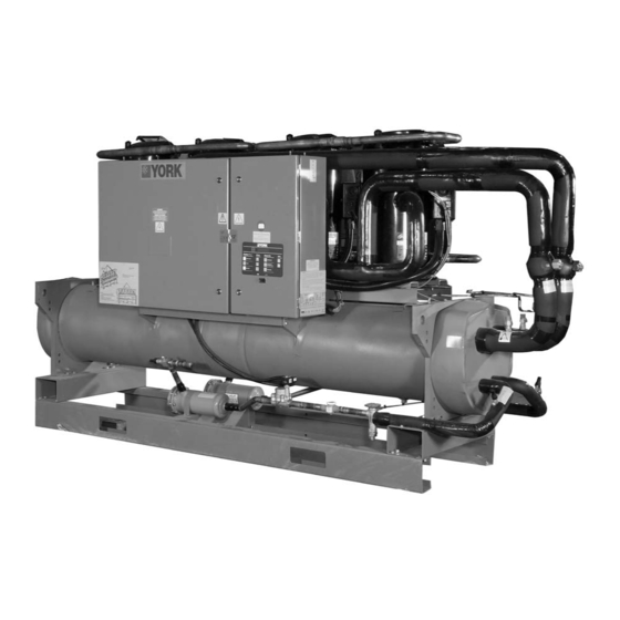
- Page 1 YCRL0200HE-YCRL0610HE Revision 0 Form 150.27-NM2.EN.CE (0312) INSTALLATION, OPERATION & MAIN TE NANCE 035-21965-100 REMOTE CONDENSER SCROLL LIQUID CHILLERS STYLE A (50 HZ) (178-556 KW) HE - HIGH EFFICIENCY R410A...
- Page 2 No external wiring is al lowed to be run through the micro panel. All wir ing must be in ac cor dance with Johnson Controls pub lished spec i fi ca tions and must be per formed only by qual i fi...
- Page 3 CHANGEABILITY OF THIS DOCUMENT In complying with Johnson Controls policy for continuous product improvement, the in for ma tion con tained in this document is subject to change without notice. While Johnson Controls makes no com mit ment to update or provide current information au to mat i cal ly to the manual owner, that information, if ap pli ca ble, can be ob tained by con tact ing the nearest Johnson Controls Service Centre.
-
Page 4: Table Of Contents
FORM 150.27-NM2.EN.CE (0312) TABLE OF CONTENTS GENERAL CHILLER INFORMATION & SAFETY HANDLING AND STORAGE INTRODUCTION ..........6 DELIVERY AND STORAGE ......20 WARRANTY ............6 INSPECTION ............ 20 SAFETY .............. 6 MOVING THE CHILLER ........ 20 Standards for Safety ..........6 Lifting by Crane/Hoist ........ - Page 5 FORM 150.27-NM2.EN.CE (0312) COMMISSIONING MAINTENANCE PREPARATION ..........31 GENERAL REQUIREMENTS ......47 Preparation - Power Off ........31 DAILY MAINTENANCE ......... 47 Soft Start (Option) ..........32 SCHEDULED MAINTENANCE ..... 47 THE MACHINE IS NOW LIVE! ..... 32 Evaporator In-Service Inspection ...... 48 FIRST TIME START-UP ........
-
Page 6: General Chiller Information & Safety
Service Centre. See Section 5, Commissioning. and manufactured to the highest design and construction standards to ensure high performance, reliability and • Only genuine Johnson Controls approved spare parts, adaptability to all types of air conditioning installations.. oils, coolants, and refrigerants must be used. -
Page 7: Fluorinated Greenhouse Gases
(R410A) that will be used in this unit is 1720. This manual and any other document supplied with the unit are the property of Johnson Controls which reserves • The refrigerant quantity required will be dependant all rights. They may not be reproduced, in whole or on system design. -
Page 8: Pressure Systems
FORM 150.27-NM2.EN.CE (0312) Pressure Systems Safety Labels The unit will contain refrigerant vapour and liquid under The following labels are fi xed to each unit to give pressure, release of which can be a danger and cause instruction, or to indicate potential hazards which may injury. -
Page 9: Material Safety Data
FORM 150.27-NM2.EN.CE (0312) MATERIAL SAFETY DATA Refrigerant Safety Data R410A: COMPOSITION/INFORMATION ON INGREDIENTS Components Material PENTAFLUOROETHANE (HFC-125) DIFLUOROMETHANE (HFC-32) CAS Number 354-33-6 75-10-5 HAZARDS IDENTIFICATION Potential Health Effects Inhalation of high concentrations of vapour is harmful and may cause heart irregularities, unconsciousness, or death. - Page 10 FORM 150.27-NM2.EN.CE (0312) Refrigerant Safety Data R410A: Extinguishing Media As appropriate for combustibles in area. Fire Fighting Instructions Cool cylinder with water spray or fog. Self-contained breathing apparatus (SCBA) is required if cylinders rupture and contents are released under fire conditions. Water runoff should be contained and neutralized prior to release.
- Page 11 FORM 150.27-NM2.EN.CE (0312) Refrigerant Safety Data R410A: Polymerization Polymerization will not occur. Other Hazards Decomposition : Decomposition products are hazardous. This material can be decomposed by high temperatures (open flames, glowing metal surfaces, etc.) forming hydrofluoric acid, and possibly carbonyl halides. TOXICOLOGICAL INFORMATION Animal Data The blend is untested.
- Page 12 FORM 150.27-NM2.EN.CE (0312) Oil Safety Data YORK 'V' Oil: Section 1 Substance Product Information Product Trade Name: YORK "V" Oil. Chemical Name: Carboxylic Ester. Section 2 Components and Hazard Statement This product is non-hazardous. This material has no known hazards under applicable laws. Section 3 Safe Handling and Storage Handling: Keep containers closed when not in use.
-
Page 13: Product Description
FORM 150.27-NM2.EN.CE (0312) PRODUCT DESCRIPTION COMPRESSOR COMPRESSOR INTRODUCTION COOLER CONTROL PANEL POWER SECTION YORK YCRL chillers are designed for water or water- Compressors glycol cooling. The unit has suction-cooled, hermetic scroll compressors. High effi ciency is achieved through a controlled orbit and All models are designed for indoor installation. -
Page 14: Evaporator
The condenser can be either a fi eld supplied YORK VDC remote air-cooled condenser (available separately from • Software is loaded into the microprocessor controller Johnson Controls) or an evaporative condenser. via a SD card, with programmed setpoints retained in a lithium battery backed real time clock (RTC) memory. -
Page 15: Programmable Setpoints
FORM 150.27-NM2.EN.CE (0312) Programmable setpoints: System Safeties: Cause individual compressors to perform auto shut • Chilled liquid temperature setpoint and range down and require manual reset in the event of 3 trips in • Remote reset temperature range a 90-minute time period: •... -
Page 16: Options & Accessories
FORM 150.27-NM2.EN.CE (0312) ACCESSORIES AND OPTIONS Compressor Acoustic Blankets Each compressor is individually enclosed in an acoustic Soft Starters sound blanket. The sound blankets are made with one layer of acoustical absorbent textile fi bre of 15 mm Factory mounted soft starters reduce the inrush current to the last compressor on each refrigerant circuit. -
Page 17: Refrigerant Flow Diagram
FORM 150.27-NM2.EN.CE (0312) REFRIGERANT FLOW DIAGRAM Low-pressure liquid refrigerant enters the cooler tubes and is evaporated and superheated by the heat energy absorbed from the chilled liquid pass- ing through the cooler shell. Low-pressure vapour enters the compressor where pressure and super- heat are increased. -
Page 18: Unit Components
FORM 150.27-NM2.EN.CE (0312) UNIT COMPONENTS CONTROL PANEL WITH KEYPAD AND SINGLE SPEED SCROLL DISPLAY COMPRESSORS ISOLATION VALVES (OPT) POWER PANEL EVAPORATOR FORMED STEEL BASE RAILS FILTER DRIERS LIQUID SIGHT LINE LIQUID LINE GLASS SOLENOID STUB-OUT VALVE VALVE SINGLE SPEED SCROLL OPTIONAL ISOLATION VALVE COMPRESSORS COMPRESSOR... -
Page 19: Model Number Nomenclature
FORM 150.27-NM2.EN.CE (0312) UNIT MODEL NUMBER NOMENCLATURE NOMENCLATURE The model number denotes the following characteristics of the unit. Y C R L - 0445 - H - E - 50 - X - AB YORK DESIGN SERIES/ CHILLER DEVELOPMENT LEVEL DOL STARTING REMOTE CONDENSER VOLTAGE CODE 50=380 - 415/3/50... -
Page 20: Handling And Storage
To ensure consistent quality and maximum reliability, Major damage must be reported immediately to your all units are tested and inspected before leaving the local Johnson Controls representative. factory. Units are shipped completely assembled and MOVING THE CHILLER containing a nitrogen holding charge. Units are shipped without export crating unless crating has been specifi... -
Page 21: Installation
FORM 150.27-NM2.EN.CE (0312) INSTALLATION Location Requirements For installation in equipment rooms near noise-critical areas, common walls should be of adequate sound To achieve optimum performance and trouble-free attenuating construction, all doors should be tightly service, it is essential that the proposed installation site gasketed, and the unit should have vibration isolators meet with the location and space requirements for the fi... -
Page 22: Water Treatment
Aerated, brackish or salt water is not recommended for exchanger should be readily de-mountable to enable use in the water systems. Johnson Controls recommends cleaning prior to operation, and to facilitate visual that a water treatment specialist be consulted to inspection of the exchanger nozzles. -
Page 23: Refrigerant Relief Valve Piping
FORM 150.27-NM2.EN.CE (0312) Refrigerant Relief Valve Piping The Installer should refer to JOHNSON CONTROLS (Yorkworks selection) for part load and full load The cooler (evaporator) is protected against internal capacities for pipe sizing / oil return issues. refrigerant over-pressure and fi re by refrigerant relief JOHNSON CONTROLS ASSUMES NO valves. - Page 24 FORM 150.27-NM2.EN.CE (0312) DISCHARGE AND LIQUID LINE CAPACITIES IN TONS FOR REFRIGERANT 410A LIQUID LINES DISCHARGE LINES (DELTA T = 1°F, DELTA P = 4.75 PSI) LINE SIZE LINE SIZE DELTA T DELTA T SATURATED SUCTION TEMPERATURE, °F DELTA P = TYPE L TYPE L VEL.
- Page 25 FORM 150.27-NM2.EN.CE (0312) MINIMUM REFRIGERATION CAPACITY IN TONS FOR OIL ENTRAINMENT UP HOT GAS RISERS (TYPE L COPPER TUBING) PIPE O.D., IN. DISCHARGE 1-1/8 1-3/8 SATURATION REFRIGERANT GAS TEMP. TEMP. °F AREA, IN2 °F 0.233 0.348 0.484 0.825 1.256 0.30 0.54 0.88 1.33...
-
Page 26: Refrigerant Line Sizing
FORM 150.27-NM2.EN.CE (0312) Refrigerant Line Sizing Refrigerant Charge Refrigerant piping systems must be designed to The chiller is charged and shipped with a dry nitrogen provide practical line sizes without excessive pressure holding charge. The chiller and the remote piping drops, prevent compressor oil from being “trapped”... -
Page 27: Ycrl Connection Sizes
FORM 150.27-NM2.EN.CE (0312) Type “K” pipe (thicker wall), per ASME B31.5-2006 The connection sizes should not be used section 504.1.2, has a rating of 50 bar (725 psi) before as a guide for sizing remote piping, since the additional 20% allowance is taken. sizing of the remote piping will vary to assure oil return and limit pressure drop. -
Page 28: Electrical Connection
This common electrical noise could cause malfunctions or damage the point of isolation is not supplied by Johnson Controls. unit and its controls. In accordance with EN 60204 it is recommended that the Power Wiring customer wiring to these terminals uses orange wires. -
Page 29: Chilled Liquid Pump Starter
FORM 150.27-NM2.EN.CE (0312) Chilled Liquid Pump Starter Remote Start/Stop Terminals 23 and 24 close to start the liquid pump. Connect a remote switch to terminals 13 and 51 to This contact is closed if there is a ‘Leaving Liquid provide remote start/stop control if required. Temperature Cutout’... -
Page 30: Connection Diagram
FORM 150.27-NM2.EN.CE (0312) CONNECTION DIAGRAM 50 Hz 400 V CUSTOMER POWER SUPPLY... -
Page 31: Commissioning
On position before commissioning then it must be Control panel: Check the panel to see that it is free of reported to Johnson Controls otherwise the warranty foreign materials (wire, metal chips, etc.) and clean out may be invalidated. -
Page 32: Soft Start (Option)
FORM 150.27-NM2.EN.CE (0312) Flow switch: Verify a chilled liquid fl ow switch is Soft Start (Option) correctly fi tted in the customer’s pipework on the cooler Due to vibration during transport the soft starter internal outlet, and wired into the control panel correctly. bypass contactor may be in a undefi... -
Page 33: First Time Start-Up
FORM 150.27-NM2.EN.CE (0312) FIRST TIME START-UP Thermal Expansion valve (when fi tted) adjustment: The expansion valves are factory set and should not need During the commissioning period there should be adjustment. If any superheat values are out of range, suffi cient heat load to run the unit under stable full however, the expansion valve adjusting screw should be load operation to enable the unit controls, and system adjusted no more than 1 turn at a time (‘in’... -
Page 34: Technical Data
FORM 150.27-NM2.EN.CE (0312) TECHNICAL DATA EVAPORATOR PRESSURE DROP GRAPH 40 50 Evaporator Flow Rate (l/s) PRESSURE DROP FORMULAE High Efficiency (HE) Models Evaporator Pressure Drop (kPa) Line YCRL0200 P= 0.3651 x Flow Rate (l/s) ^ 1.8204 YCRL0230 P= 0.2240 x Flow Rate (l/s) ^ 1.8204 YCRL0260 P= 0.2542 x Flow Rate (l/s) ^ 1.8425 YCRL0300... -
Page 35: Operating Limitations - Ycrl-He
FORM 150.27-NM2.EN.CE (0312) OPERATING LIMITATIONS - YCRL-HE 0200 0230 0260 0300 0345 YCRL Condenserless Models Min. Max. Min. Max. Min. Max. Min. Max. Min. Max. 4.5 to 15 Liquid Outlet Temperature (Water) °C 3 to 8 Liquid Outlet Temperature Range °C Chilled Liquid Evaporator Flow Rate... -
Page 36: Physical Data - Ycrl-He
FORM 150.27-NM2.EN.CE (0312) PHYSICAL DATA - YCRL-HE Condenserless YCRL-HE Models 0200 0230 0260 0300 0345 Number of refrigerant circuits Oil Charge Circuit 1 / Circuit 2 8.3/8.3 12.4/12.4 9.3/8.3 14/12.4 9.3/9.3 Number of Compressors Scroll Type Compressor 100/74/ 100/71/ 100/74/ 100/74/ 100/71/ Capacity Control... -
Page 37: Electrical Data - Ycrl He
FORM 150.27-NM2.EN.CE (0312) ELECTRICAL DATA - YCRL HE High Efficiency Units Start up Start up Nominal Running Maximum Running Amps Amps Conditions Conditions YCRL Direct Optional Amps Amps Amps on Line Soft Start at 400 V at 360V at 400V 0200 0230 0260... - Page 38 FORM 150.27-NM2.EN.CE (0312) DIMENSIONS - YCRL0200HE, 0230HE, 0260HE, 0300HE AND 0345HE...
- Page 39 FORM 150.27-NM2.EN.CE (0312)
-
Page 40: Dimensions - Ycrl0200He, Ycrl0230He, Ycrl0260He, Ycrl0300He, Ycrl0345He 38 Dimensions - Ycrl0385He, Ycrl0445He, Ycrl0530He And Ycrl0610He
FORM 150.27-NM2.EN.CE (0312) DIMENSIONS - YCRL0385HE, 0445HE, 0530HE AND 0610HE... - Page 41 FORM 150.27-NM2.EN.CE (0312)
-
Page 42: Durulene Isolator Specifications
FORM 150.27-NM2.EN.CE (0312) DURULENE ISOLATOR SPECIFICATIONS MOLDED DURULENE DIA. AD THRU TYP 2 PLACES Dimensions (inches) Mount Type 5.50 3.38 2.88 4.13 0.56 0.25 1/2-13UNC x 1 2.50 6.25 4.63 2.75 5.00 0.56 0.38 1/2-13UNC x 1 3.00 Weight Range (kgs)* Type Colour York P/N... -
Page 43: Durulene Isolator Installation
FORM 150.27-NM2.EN.CE (0312) DURULENE ISOLATOR INSTALLATION TOP BOLT ("B") TOP WASHER ("C") ("B") ("A") SECTION D-D 4. Bolt or anchor all isolators to supporting structure 1. Read the following instructions before beginning utilising base thru holes (“B”). installation. 5. Remove top bolt and top washer. Place equipment on 2. -
Page 44: 25 Mm Isolator Specification
FORM 150.27-NM2.EN.CE (0312) 25 MM ISOLATOR SPECIFICATION 5/8" Ø1/2" H" C" T" B" L" D" W" Dimensions (inches) Mount Type 0.625 7.75 4.75 5.625 0.625 10.5 9.25 7.75 0.5625 Weight Range (kgs)* Type Colour York P/N 345 to 463 Grey 029-25334-004 463 to 525 White... -
Page 45: 25 Mm Isolator Installation
FORM 150.27-NM2.EN.CE (0312) 25 MM ISOLATOR INSTALLATION EQUIPMENT POSITIONING BASE UPPER PIN (H) HOUSING 0.25” min - 0.5” max LOWER HOUSING NON-SKID ELASTOMERIC 5. Place equipment on top of isolators making sure that 1. Read the following instructions before beginning mounting holes of the equipment line up with isolator installation. -
Page 46: Unit Operation
FORM 150.27-NM2.EN.CE (0312) UNIT OPERATION GENERAL DESCRIPTION NORMAL RUNNING AND CYCLING The units are designed to work independently, or in Once the unit has been started, all operations are fully conjunction with other equipment via a YORK ISN automatic. After an initial period of operation with the building management system or other automated control lead compressor, the control system will adjust the unit system. -
Page 47: General Requirements
Johnson Controls Service Centre. out every three to six months and a ‘major’ service once a year. It is recommended that your local Johnson Controls Unit status: Press the ‘STATUS’ key on the keypad Service Centre is contacted for recommendations for and ensure no fault messages are displayed (refer to individual sites. -
Page 48: Evaporator In-Service Inspection
This allowance is suffi cient to cover the lifetime of the unit. Johnson Controls believes that periodic in service proof testing (e.g.; hydro tests) is not required. However, Johnson Controls recognises that national regulations... -
Page 49: Trouble Shooting
FORM 150.27-NM2.EN.CE (0312) TROUBLE SHOOTING Competent Persons Trouble Shooting Guide PROBLEM POSSIBLE CAUSE ACTION No display on panel — Unit will not Mains supply to unit off. Switch on mains supply if safe to do so. operate Emergency stop device off. Check if remote emergency stop device is in the ‘OFF’... - Page 50 FORM 150.27-NM2.EN.CE (0312) PROBLEM POSSIBLE CAUSE ACTION SYS X HIGH DSCH PRES displayed Discharge pressure cut-out incorrectly Adjust in accordance with recommended set. setting. Air in refrigerant system. Check for non-condensables (air) in system. Evacuate and recharge system. Excessive refrigerant charge. Remove refrigerant.
-
Page 51: Sensor Calibration Charts
FORM 150.27-NM2.EN.CE (0312) Sensor Calibration Charts Liquid Temperature (-BLCT and BECT) Discharge Pressure (-BDP) and Suction (-BSP) Transducers Temperature Resistance Microboard Sensor 0 - 400 PSI Transducer 0 - 600 PSI Transducer °C ohms Voltage Voltage Pressure Voltage Pressure Voltage barg barg 14896... -
Page 52: Spare Parts
Details of unit spare parts are given in the Renewal Parts List 035-21977-000. Contact your local Johnson Controls Sales and Service Centre for information and please quote the unit model number and serial number. -
Page 53: Decommissioning. Dismantling And Disposal
FORM 150.27-NM2.EN.CE (0312) DECOMMISSIONING. DISMANTLING AND DISPOSAL Never release refrigerant to the atmosphere If glycol or similar solutions have been when emptying the refrigerating circuits. used in the water system, or chemical Suitable retrieval equipment must be used. additives are contained, the solution MUST If reclaimed refrigerant cannot be reused. -
Page 54: Annex A - Installer Responsibilities
Johnson Controls cannot supply pressure if double risers are required for adequate part/full relief valves here because Johnson Controls will not load oil return. Please refer to installation section know what the fi nal installed pressure components for some guidance. -
Page 55: Relevant Ec Directives
FORM 150.27-NM2.EN.CE (0312) Relevant EC directives: Pressure Equipment Directive 97/23/EC Machinery Safety 2006/42/EC EMC2004/108/EC. Applied harmonized standards: EN60204-1(2006), EN378-2(2008)/A1(2009)*, EN61000-6-4(2007), EN61000-6-2(2005) * Safety accessories according to essential requirements in PED paragraph 2.11.1 have been calculated according to EN13136:2001/A1:2005 and are not following the requirements in EN378-2:2008 paragraph 6.2.6.2, unless dual relief valves are fi... - Page 56 www.johnsoncontrols.com Form 150.27-NM2.EN.CE (0312) Subject to change without notice. Revision 0 ALL RIGHTS RESERVED...
Need help?
Do you have a question about the York YCRL0200HE and is the answer not in the manual?
Questions and answers