Table of Contents
Advertisement
Advertisement
Table of Contents

Related Manuals for Johnson Controls York YCSE 040


Summary of Contents for Johnson Controls York YCSE 040
- Page 1 Библиотека СОК YCSE040-YCSE100 & YCRE040-YCRE100 INSTALLATION, COMMISSIONING, Revision 1 Form 035-21786-100 (0909) OPERATION & MAINTENANCE WATER AND REMOTE AIR COOLED LIQUID CHILLERS WITH SCREW COMPRESSORS STYLE B (YCSE 134-320KW) (YCRE 127-307KW) Aspak R407C...
-
Page 3: Table Of Contents
035-21786-100 Rev. 1 (0909) TABLE OF CONTENTS SUPPLIER INFORMATION INSTALLATION Introduction Location Requirements Warranty Installation of Vibration Isolators Safety Pipework Connection Responsibility for Safety Water Treatment About this Manual Pipework Arrangement Misuse of Equipment Connection Types & Sizes Emergency Shutdown Condenser Cooling Liquid Systems 4.4 Safety Labels Electrical Connection... - Page 4 035-21786-100 Rev. 1 (0909) TROUBLE SHOOTING Competent Persons Trouble Shooting Guide TECHNICAL DATA Flow Rate and Pressure Drop Graphs Performance Graphs Operating Limitations Physical Data Electrical Data Sound Data Clearances and Foundations Dimensions 10 SPARE PARTS 10.1 Renewal Parts List 10.1 10.2 Recommended Compressor Oils 10.1...
-
Page 5: Supplier Information
Low Voltage Directive (2006/95/EC) Warranty EMC Directive (2004/108/EC) Johnson Controls warrants all equipment and materials They conform to the applicable and essential safety against defects in workmanship and materials for one requirements of Pressure Equipment Directive year from initial start-up, or eighteen months from 97/23/EC and bear CE marking. -
Page 6: Responsibility For Safety
This manual and any other document supplied with the pressure, release of which can be a danger and cause unit, are the property of Johnson Controls which injury. The user should ensure that care is taken during reserves all rights. They may not be reproduced, in... -
Page 7: Emergency Shutdown
035-21786-100 Rev. 1 (0909) Electrical Safety Labels The unit must be earthed. No installation or The following labels are fixed to each unit to give maintenance work should be attempted on electrical instruction, or to indicate potential hazards which may equipment without first switching off, isolating and exist. -
Page 8: Material Safety Data
035-21786-100 Rev. 1 (0909) Material Safety Data Refrigerant Data: Safety Data R407C Toxicity Low. In contact with skin Liquid splashes or spray may cause freeze burns. Unlikely to be hazardous by skin absorption. Thaw affected areas with water. Remove contaminated clothing carefully — may adhere to skin in case of freeze burns. - Page 9 035-21786-100 Rev. 1 (0909) Thermal and Acoustic Materials Data Health Hazard & First Toxicity Index <10 to NES713 Issue 3 (1991): Non-hazardous, non-toxic. No first aid necessary. Stability / Reactivity Stable. Handling / Use / No special handling precautions required. Dispose of according to local laws and regulations Disposal governing non-biodegradable non-hazardous solid wastes.
- Page 10 035-21786-100 Rev. 1 (0909) Health Hazard Data Route(s) of Entry No significant health hazards are identified. Prolonged repeated skin contact may cause irritation and dermatitis Health Hazards (Acute and Chronic) No significant health hazards are identified. Prolonged repeated skin contact may cause irritation and dermatitis Carcinogenicity NTP: No IARC Monographs: No...
-
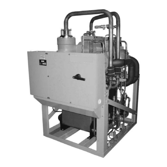
Page 11: Product Description
035-21786-100 Rev. 1 (0909) Compressor Evaporator Condenser (YCSE only) Power Section Control Panel Refrigerant Circuits PRODUCT DESCRIPTION Depending on model size, one or two independent Introduction refrigerant circuits are provided on each unit. Each circuit uses copper refrigerant pipe formed on computer YORK YCSE/YCRE R407C chillers are designed for controlled bending machines to reduce the number of water or water-glycol cooling. -
Page 12: Power And Control Panels
035-21786-100 Rev. 1 (0909) Accessories and Options Modbus 1 2-Pole Motor To integrate the unit into the building management 2 Built-in Oil Separator system. The interface permits the connection of up to 8 3 Twin Screw Rotors 4 Oil Sight Glass units using the Modbus communications protocol. -
Page 13: Nomenclature
035-21786-100 Rev. 1 (0909) Dual Pressure Relief Valves AVM (Spring Isolators) Two safety valves in parallel of which one is operational Spring and cage type isolators for mounting under the to assist in valve replacement during maintenance. unit base rails to avoid transmission of vibration to the plant room structure (supplied loose with unit for field Suction Pressure Relief Valves assembly) -
Page 14: Refrigerant Flow Diagram
035-21786-100 Rev. 1 (0909) Refrigerant Flow Diagram YCSE 040, 050, 060, 100 Models Compressor Compressor Safety Valve (Option) Check Valve Compressor Dual Safety Valve (Option) Pressure Relief Valve Thermistor - Suction Stop Valve (Option) Thermistor - Discharge Condenser Thermistor - Evaporator Stop Valve - Refrigerant Charge Point Thermistor - Evaporator Water Inlet Stop Valve... - Page 15 035-21786-100 Rev. 1 (0909) YCSE 080 Models Compressor Pressure Switch Check Valve Solenoid Valve Pressure Relief Valve Capillary Tube Stop Valve (Option) Economiser Condenser Strainer Stop Valve - Refrigerant Charge Point Thermistor - Suction Stop Valve Thermistor - Discharge Drier Thermistor - Evaporator Sight Glass Thermistor - Evaporator Water Inlet...
- Page 16 035-21786-100 Rev. 1 (0909) YCRE 040, 050, 060, 080, 100 Models Compressor High Pressure Sensor Stop Valve Compressor Safety Valve (Option) Check Valve Compressor Dual Safety Valve (Option) Pressure Relief Valve (Field Supplied) Thermistor - Suction Remote Condenser (Field Supplied) Thermistor - Discharge Stop Valve Thermistor - Evaporator...
-
Page 17: Transportation, Handling And Storage
Units are Major damage must be reported immediately to your shipped without export crating unless this has been local Johnson Controls representative. specified on the Sales Order. Moving the Unit If the unit is to be put into storage, before installation, the... -
Page 18: Lifting Weights
035-21786-100 Rev. 1 (0909) Moving the Unit with Rollers To prevent the unit tipping over do not tilt the unit more than 15°. Use at least 6 equal sized rollers under the base frame. Each roller must support both outer frames. Ensure the unit is balanced evenly on all the rollers. -
Page 19: Installation
The unit must be installed on a suitable flat and level type flow switches suitable for 10 barg working concrete base (2) that extends to fully support the unit pressure can be obtained from Johnson Controls base frame. as an option for the unit. -
Page 20: Water Treatment
035-21786-100 Rev. 1 (0909) Pipework and fittings must be separately Any debris left in the water pipework between supported to prevent any loading on the heat the strainer and heat exchanger could cause e x c h a n g e r ( s ) . F l e x i b l e c o n n e c t i o n s a r e serious damage to the plates in the heat r e c o m m e n d e d w h i c h w i l l a l s o m i n i m i s e exchanger and must be avoided. -
Page 21: Pipework Arrangement
035-21786-100 Rev. 1 (0909) Pipework Arrangement The following are suggested pipework arrangements for single unit installations. For multiple unit installations, each unit should be piped as shown. Recommendations of the Building Services Research Association Chilled Liquid System / Binder Point Connection Types &... -
Page 22: Condenser Cooling Liquid Systems
035-21786-100 Rev. 1 (0909) If relief pipework is common to more than one valve its Inlet Temperature Control (By others) cross sectional area must be at least the total required by each valve. Valve types should not be mixed on a For a cooling tower / dry cooler system, the simplest common pipe. -
Page 23: Electrical Connection
035-21786-100 Rev. 1 (0909) Electrical Connection liquid valves on the unit itself. Liquid subcooling should be 4°C to 10°C on arrival at the unit. The following connection recommendations are It is important to ensure that for each system the remote intended to ensure safe and satisfactory operation of the unit. - Page 24 035-21786-100 Rev. 1 (0909) Maximum Equivalent Maximum Difference Refrigerant Connections Piping Length (m) in Height (m) Units are supplied with a nitrogen holding charge. Do Unit below not open the unit stop valves until all preparation for field Remote 30.0 25.0 leakage checks has been completed.
- Page 25 035-21786-100 Rev. 1 (0909) YCRE Refrigerant Piping Arrangements Field Supplied Liquid Loop Liquid Loop Unit below Remote Condenser Remote Remote Condenser Condenser Oil Trap Oil Trap Maximum 25 metres At each At each 10 metres 10 metres YCRE Unit Oil Trap Oil Trap Receiver Receiver...
-
Page 26: 4.10 Power Wiring
035-21786-100 Rev. 1 (0909) 4.10 Power Wiring 4.11 Control Wiring The units are suitable for 380 or 400 V, Connect the interlock and control wiring as shown in the unit connection diagram below. 3 phases + neutral + earth, 50 Hz nominal supplies only. -
Page 27: 4.12 Connection Diagram
035-21786-100 Rev. 1 (0909) 4.12 Connection Diagram YCSE Name N° Main Power/Terminal Board (R,S,T,N) Electrical Box Main Power Switch Main Power Wiring Earth Wiring T he main connection to terminal N is required. Remove link between 5 and 6 when remote control switch option is fitted 30mA max EVAP... - Page 28 035-21786-100 Rev. 1 (0909) YCRE Name N° Main Power/Terminal Board (R,S,T,N) Electrical Box Main Power Switch Main Power Wiring Earth Wiring The main connection to terminal N is required. Remove link between 5 and 6 when remote control switch option is fitted 30mA max EVAP SW4 SW5 SW6...
-
Page 29: Commissioning
035-21786-100 Rev. 1 (0909) Compressor oil: Check the compressor oil for correct COMMISSIONING level at the oil level sight glass. Full at commission startup and no less than half full during normal Preparation operation. Commissioning of this unit should only be Isolation/protection: Verify that all sources of electrical carried out by JCI Authorised personnel who supply to the unit are taken from point(s) of isolation. -
Page 30: First Time Start-Up
035-21786-100 Rev. 1 (0909) Cooler and Condenser flow rates and Refrigerant flow: When a compressor starts a flow of pressure drops must be within the limits given liquid refrigerant will be seen in the liquid line sight glass. in Section 9. Operation outside of these limits After several minutes operation and providing a full is undesirable and could cause damage. -
Page 31: Unit Operation
035-21786-100 Rev. 1 (0909) To prevent damage to the unit the control UNIT OPERATION supply to the compressor heaters should not be switched off, even when the unit is not General Description required to run. The units are designed to work independently, or in conjunction with other equipment via a building If mains power must be switched off, (for extended management system or other automated control... - Page 32 035-21786-100 Rev. 1 (0909) The modes are changed by using the display check This example shows that alarm 10 was a system 1 high switches SW3 and SW4. pressure alarm and alarm 9 was a system 2 high pressure alarm. See Alarm Codes, Pressure/ Temperature Settings and Safety and Control Device Normal Operating Mode Settings.
- Page 33 035-21786-100 Rev. 1 (0909) Evaporating Temperature (°C): 4°C Compressor Capacity Control (°C) Load up Evaporating Temperature (°C): 4°C Compressor Capacity Control (°C) Hold Chilled Water Inlet Temperature (°C): 12°C Compressor Capacity Control (°C) Load down Chilled Average Water Outlet Temperature (°C): 7°C Control Status Compressor Start Control C D C...
- Page 34 035-21786-100 Rev. 1 (0909) Second Water Temperature Setting This temperature setting provides another setting value for water temperature. It can be changed by a remote signal. Select the Parameter Settings Mode by pressing and holding SW4 for 3 seconds. Press SW4 q to scroll through the parameter settings until the second water temperature setting display is shown: This shows the setting is 6°C.
- Page 35 035-21786-100 Rev. 1 (0909) Alarm Codes Alarm Display Code Alarm Display Code Function Function No. 1 Comp. No.2 Comp. No. 1 Comp. No.2 Comp. Water Failure for Condenser (Differential Pressure Switch or C1-H1 C2-H2 High Pressure C3-P6 C3-P6 Flow switch option) (YCSE only) Alarm of Water Failure 6E-6E...
- Page 36 035-21786-100 Rev. 1 (0909) Pressure/Temperature Settings Cooling Liquid Water (DSW4-4: OFF) Brine/Glycol (DSW4-4: ON) 5 to 20 -5 to 5 -10 to -6 Leaving Liquid Temp (°C) If Ps < 3.7bar, starts loading If Ps < 0.9bar, starts loading If Ps < 0.2bar, starts loading Protection down for 10 secs and then down for 10 secs and then...
- Page 37 035-21786-100 Rev. 1 (0909) Standard Operating Sequence - YCSE-040, 050, 060, 080, YCRE-040, 050, 060 Control Stage Control Devices Starting Control Capacity Control Safety Devices Shut Down Main Power Switch Chilled Water Pump Condenser Water Pump Operation Switch (ON/OFF) Load Up Controller Neutral Load Down...
- Page 38 035-21786-100 Rev. 1 (0909) 6.5.2 Control Printed Circuit Board The Control Printed Circuit Board contains various switches for setting the unit control parameters. Switch Function Factory Default RSW 1 Chilled Water Outlet Temperature Setting Switch RSW 2 Chilled Water Outlet Temperature Setting Switch RSW 3 Hot Water Outlet Temperature Setting Switch (heat pump option only) RSW 4...
- Page 39 035-21786-100 Rev. 1 (0909) Switch Function Factory Default DSW1 Not Used DSW2-1 3 Mins Compressor Starting Time Delay DSW2-2 OFF/OFF DSW3-1 Compressor Isolation for Maintenance ON/ON DSW3-2 DSW3-3 to Not Used DSW3-7 DSW3-8 Sets chiller ID when using more than one chiller with a remote control DSW3-9 OFF/OFF/OFF system...
- Page 40 035-21786-100 Rev. 1 (0909) Chilled Water Outlet Temperature Setting Switch Temperature Band for Stop Setting Switch RSW1 and RSW2 DSW5-1, DSW5-2 7 ° C fo r c h i l l e d w a t e r o u t l e t te m p e r a t u r e is 1°C degree is factory default: DSW5-1 ON;...
- Page 41 035-21786-100 Rev. 1 (0909) Interval of Output Signal Time for Load-up 2 and Manual Set Switch A: DSW3-8, DSW3-9, DSW3-10 Load-down Mode Setting Switch: DSW5-9, DSW5-10 This switch is used to set the chiller ID when using more than one chiller with a remote control system (HARC, 60 seconds is factory default: DSW5-9 ON;...
- Page 42 035-21786-100 Rev. 1 (0909) Manual Set Switch C: DSW7-1, DSW7-2, Selection Switch for Cooling/ Heating Operation: This switch defines the chilled liquid temperature range. Factory default is COOL, SW8 in the up position. The settings for DSW7-1, DSW7-2 are as follows: If the optional heat pump is fitted, set SW8 to the down DSW7 position for HEATING operation.
-
Page 43: Maintenance
035-21786-100 Rev. 1 (0909) Unit status: If the Alarm LED is on select the Alarm MAINTENANCE Mode on the display by pressing and holding SW3 and SW4 for 3 seconds. General Requirements Press SW3 p or SW4 q to scroll through the alarms. The units have been designed to operate continuously The display will automatically toggle (E) between the provided they are regularly maintained and operated... -
Page 44: Scheduled Maintenance
035-21786-100 Rev. 1 (0909) Scheduled Maintenance The maintenance operations detailed in the following table should be carried out on a regular basis by a suitably qualified Service Engineer. It should be noted that the interval necessary between each ‘minor’ and ‘major’ service can vary depending on, for instance, application, site conditions and expected operating schedule. -
Page 45: Trouble Shooting
035-21786-100 Rev. 1 (0909) Trouble Shooting Competent Persons Trouble Shooting Guide PROBLEM POSSIBLE CAUSE ACTION Compressor does not operate Interlock circuit for chilled water Check the pump contactor. Repair or replace, if pump is open necessary. Check the pump. Electrical protective devices have Locate and rectify the fault. - Page 46 035-21786-100 Rev. 1 (0909) PROBLEM POSSIBLE CAUSE ACTION High Discharge Pressure Warm inlet water or insufficient Open the valve water flow through the condenser Gas outlet valve on the condenser Check the valves, capillary tubes and strainer. Replace, not completely open if necessary.
-
Page 47: Technical Data
035-21786-100 Rev. 1 (0909) TECHNICAL DATA Flow Rate and Pressure Drop Graphs YCSE/YCRE Evaporator Water Pressure Drop YCSE Condenser Water Pressure Drop... -
Page 48: Performance Graphs
035-21786-100 Rev. 1 (0909) Performance Graphs Discharge Pressure - Water Cooled Condenser Discharge Pressure - Air Cooled Condenser... - Page 49 035-21786-100 Rev. 1 (0909) Suction Pressure - Evaporator Sub-cooling Temperatures...
-
Page 50: Operating Limitations
035-21786-100 Rev. 1 (0909) Operating Limitations YCSE040 YCSE050 YCSE060 YCSE080 YCSE100 Standard Models Min. Max. Min. Max. Min. Max. Min. Max. Min. Max. Liquid Outlet Temperature °C 5 to 15 (Water) Liquid Outlet Temperature (1) (3) °C -10 to 15 (Glycol) Liquid Outlet Temperature Chilled Liquid... -
Page 51: Physical Data
035-21786-100 Rev. 1 (0909) Physical Data Standard Models YCSE Number of refrigerant circuits 14 / 14 Refrigerant Charge Circuit 1 (/ Circuit 2) Oil Charge Circuit 1 (/ Circuit 2) litre Number of Compressors Compressor Semi-hermetic Screw Type 15-100 Capacity Control 7.5,15-100 Number of Evaporator Brazed PHE... -
Page 52: Electrical Data
035-21786-100 Rev. 1 (0909) Electrical Data Nominal Running Maximum Running Start up Conditions Conditions YCSE Amps Amps Amps at 400 V at 400V (1) Nominal Running Amps at 7ºC Leaving Evaporator Liquid Temperature and 35ºC Leaving Condenser Liquid Temperature (2) Maximum Running Amps is the maximum unit running current under the following conditions: Supply voltage: 90% of rated voltage;... -
Page 53: Sound Data
035-21786-100 Rev. 1 (0909) Sound Data Mean Sound Power Band Levels - Frequency Hz YCSE 1000 2000 4000 8000 EN 292-1991 Notes: 1. Sound Power as per Eurovent Specification. 2. Sound Pressure values for EN 292-1991, 1 metre from Control Panel and 1.5 metres from Ground Level in dB(A) Mean Sound Power Band Levels - Frequency Hz YCRE... -
Page 54: Clearances And Foundations
035-21786-100 Rev. 1 (0909) Clearances and Foundations... -
Page 55: Dimensions
035-21786-100 Rev. 1 (0909) Dimensions Model YCSE 040... - Page 56 035-21786-100 Rev. 1 (0909) Model YCSE 050...
- Page 57 035-21786-100 Rev. 1 (0909) Model YCSE 060...
- Page 58 035-21786-100 Rev. 1 (0909) Model YCSE 080...
- Page 59 035-21786-100 Rev. 1 (0909) Model YCSE 100...
- Page 60 035-21786-100 Rev. 1 (0909) Model YCRE 040...
- Page 61 035-21786-100 Rev. 1 (0909) Model YCRE 050...
- Page 62 035-21786-100 Rev. 1 (0909) Model YCRE 060...
- Page 63 035-21786-100 Rev. 1 (0909) Model YCRE 080...
- Page 64 035-21786-100 Rev. 1 (0909) Model YCRE 100...
-
Page 65: Spare Parts
035-21786-100 Rev. 1 (0909) SPARE PARTS 10.1 Renewal Parts List Details of unit spare parts are given in 035-021787-000. Contact your local JCI Sales and Service Centre for information and please quote the unit model number and serial number. When ordering spare parts, we will require the following information to ensure the correct parts are supplied: Full unit model number, serial number, application and details of the parts required. - Page 66 035-21786-100 Rev. 1 (0909) This Page Intentionally Blank...
-
Page 67: Decommissioning. Dismantling And Disposal
035-21786-100 Rev. 1 (0909) If glycol or similar solutions have been DECOMMISSIONING. DISMANTLING used in the water system, or chemical AND DISPOSAL additives are contained, the solution MUST be disposed of in a suitable and safe N e v e r r e l e a s e r e f r i g e r a n t t o t h e manner. - Page 68 www.johnsoncontrols.com Subject to change without notice. Form 035-21786-100 Rev. 1 (0909) ALL RIGHTS RESERVED.
Need help?
Do you have a question about the York YCSE 040 and is the answer not in the manual?
Questions and answers