Table of Contents
Advertisement
62079
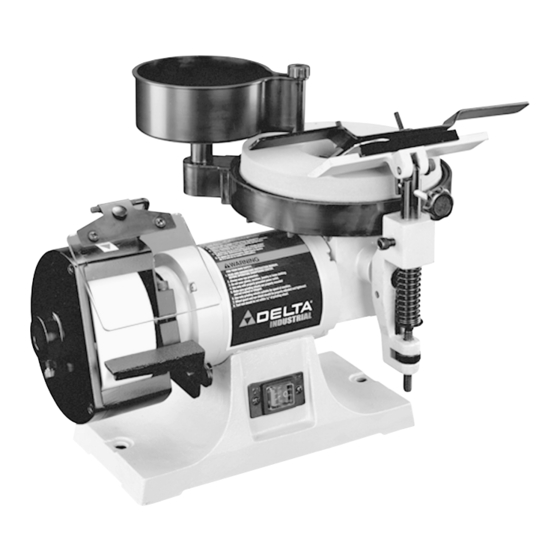
Sharpening Center
(Model 23-710)
PART NO. 1346949 - 05-14-04
Copyright © 2004 Delta Machinery
To learn more about DELTA MACHINERY
RTD10000127AA
visit our website at: www.deltamachinery.com.
For Parts, Service, Warranty or other Assistance,
1-800-223-7278 (
1-800-463-3582).
please call
In Canada call
Advertisement
Table of Contents

Related Manuals for Delta Industrial 23-710


Summary of Contents for Delta Industrial 23-710
- Page 1 62079 Sharpening Center (Model 23-710) PART NO. 1346949 - 05-14-04 Copyright © 2004 Delta Machinery To learn more about DELTA MACHINERY RTD10000127AA visit our website at: www.deltamachinery.com. For Parts, Service, Warranty or other Assistance, 1-800-223-7278 ( 1-800-463-3582). please call In Canada call...
-
Page 2: Safety Guidelines - Definitions
If you have any questions relative to a particular application, DO NOT use the machine until you have first contacted Delta to determine if it can or should be performed on the product. - Page 3 Delta may cause damage to the machine or injury to 2. WEAR EYE PROTECTION. ALWAYS USE SAFETY the user. GLASSES. Also use face or dust mask if cutting 14.
- Page 4 ADDITIONAL SAFETY RULES FOR SHARPENING CENTERS FAILURE TO FOLLOW THESE RULES MAY RESULT IN SERIOUS INJURY. DO NOT OPERATE THIS MACHINE until it is and/or serious injury. completely assembled and installed according to the 16. CLEAN THE MACHINE thoroughly when processing instructions.
-
Page 5: Power Connections
POWER CONNECTIONS A separate electrical circuit should be used for your machines. This circuit should not be less than #12 wire and should be protected with a 20 Amp time lag fuse. If an extension cord is used, use only 3-wire extension cords which have 3- prong grounding type plugs and matching receptacle which will accept the machine’s plug. -
Page 6: Extension Cords
FOREWORD The Delta Industrial Sharpening Center Model 23-710 has a 1/5 HP motor. It also comes with a 5” diameter, 120 grit aluminum oxide dry wheel, an 8” diameter, 1000-grit wet wheel, a tool rest and base, a sliding tool holder, a water tank,... -
Page 7: Unpacking And Cleaning
UNPACKING AND CLEANING Carefully unpack the machine and all loose items from the shipping container(s). Remove the protective coating from all unpainted surfaces. This coating may be removed with a soft cloth moistened with kerosene (do not use acetone, gasoline or lacquer thinner for this purpose). After cleaning, cover the unpainted surfaces with a good quality household floor paste wax. - Page 8 ASSEMBLY FOR YOUR OWN SAFETY, DO NOT CONNECT MACHINE TO THE POWER SOURCE UNTIL THE MACHINE IS COMPLETELY ASSEMBLED AND YOU HAVE READ AND UNDERSTAND THE ENTIRE INSTRUCTION MANUAL. ASSEMBLING AND ADJUSTING EYESHIELD 1. Position eyeshield (A) Fig. 3, under lip of frame (B). Line up holes in eyeshield (A) with holes in frame (B) and fasten eyeshield to frame using two 1/2”...
- Page 9 ASSEMBLING AND ADJUSTING TOOL REST FOR DRY WHEEL 1. Assemble dry wheel tool rest (A) Fig. 7, to mounting arm (B) using flat washer (C), lockwasher (D) and 5/8” long hex head screw (E). Place a lockwasher then a flat washer on the hex head screw, then assemble tool rest to mounting arm as shown in Fig.
- Page 10 ASSEMBLING AND ADJUSTING TOOL AND CHISEL HOLDER 1. Take the tool and chisel holder base and insert its mounting post (A) Fig. 11, into hole (B) in the front of the machine, and tighten screw (C) against groove (E) of mounting post. Use the provided wrench (D) Fig.
- Page 11 6. Place tool and chisel holder (K) Fig. 15, in position on base (J). Fig. 15 7. Fig. 16, illustrates tool and chisel holder (K) in position on tool rest base (J). 8. To raise or lower the tool and chisel holder assembly (E) Fig.
- Page 12 2. The water tank (B) Fig. 19, can be rotated to direct the water from the spigot (D) onto the grinding wheel. The ideal position of the spigot (D) would be to the center (C) of the grinding wheel. 3. To control the flow of water from the spigot (D) Fig. 19, turn knob (E).
-
Page 13: Operation
OPERATION USING TOOL AND CHISEL HOLDER The tool and chisel holder is supplied as standard equip- ment with your sharpening center and is ideal for sharp- ening wood chisels, plane irons, some lathe turning tools, etc. To use the tool and chisel holder, proceed as follows. - Page 14 STARTING AND STOPPING MACHINE The switch (A) Fig. 30, is located on the front of the grinder base inside a water resistant enclosure. To turn the machine “ON” push the left hand portion of the switch. To turn the machine “OFF” push the right hand portion of the switch.
- Page 15 3. Remove the tool rest and mounting post (E) Fig. 35, from the wet wheel side of the machine and insert post of tool rest assembly into hole (F). Tighten screw (G) into groove of mounting post. All controls and adjustments for the tool rest are explained in the section “ASSEMBLING AND ADJUSTING TOOL AND CHISEL HOLDER.”...
- Page 16 4. Place sliding tool rest (K) Fig. 40, in position on base (J). Fig. 40 5. Fig. 41, illustrates sliding tool rest (K) in position on tool rest base (J). 6. To level sliding tool rest (K) Fig. 42, with the wet grinding wheel, loosen screw (L), rotate complete tool rest base (E) right or left until tool rest (K) is level with the wet grinding wheel and tighten screw (L).
- Page 17 8. To tilt the sliding tool rest (K) Fig. 45, to conform with the angle of the knife to be sharpened, turn the tool rest tilting knob (P). Fig. 45 USING ACCESSORY 23-715 SLIDING TOOL REST ON DRY WHEEL When sharpening planer or jointer knives that have deep nicks, the knives can first be rough ground on the dry grinding wheel, using the sliding tool rest, before fine sharpening is performed on the wet wheel.
- Page 18 Fig. 49 Fig. 50 3. Remove sliding tool rest and mounting post (E) Fig. 49, from the wet wheel side of the machine and insert post of tool rest assembly into hole (F). Tighten screw (G) into groove (J) of mounting post (E). 4.
- Page 19 3. Place sliding tool rest (G) Fig. 53, onto the tool rest base (H) as shown. 4. Adjust the height of tool rest base (H) Fig. 54, by moving locking lever (J) to the right and turning raising and lowering knob (K) until knife (B) Fig. 53, lightly touches grinding wheel (L).
- Page 20 REPLACING WET GRINDING WHEEL DISCONNECT THE MACHINE FROM THE POWER SOURCE. 1. Using the wrench (A) Fig. 58, supplied, remove the wheel locking nut (B). 2. Remove and replace the wet wheel (C) as shown in Fig. 59. Fig. 58 Fig.
-
Page 21: Maintenance
DRESSING THE DRY GRINDING WHEEL A stick type dresser (A) Fig. 63, is supplied with your sharpening center to dress the dry grinding wheel. Bring the dresser stick (A) forward on the tool rest until it just touches the high point of the face of the wheel and dress the wheel by moving the dresser stick back and forth. -
Page 22: Parts, Service Or Warranty Assistance
Two Year Limited New Product Warranty Delta will repair or replace, at its expense and at its option, any new Delta machine, machine part, or machine accessory which in normal use has proven to be defective in workmanship or material, provided that the customer returns the product prepaid to a Delta factory service center or authorized service station with proof of purchase of the product within two years and provides Delta with reasonable opportunity to verify the alleged defect by inspection. - Page 23 NOTES...
- Page 24 Fax: (519) 767-4131 Fax: (604) 420-3522 Fax: (514) 336-3505 The following are trademarks of PORTER-CABLE • DELTA (Las siguientes son marcas registradas de PORTER-CABLE • DELTA S.A.) (Les marques suivantes sont des marques de fabriquant de la PORTER-CABLE • DELTA): Auto-Set ®...
Need help?
Do you have a question about the Industrial 23-710 and is the answer not in the manual?
Questions and answers