Table of Contents
Advertisement
To learn more about DELTA MACHINERY
visit our website at: www.deltamachinery.com.
For Parts, Service, Warranty or other Assistance,
1-800-223-7278 (
please call
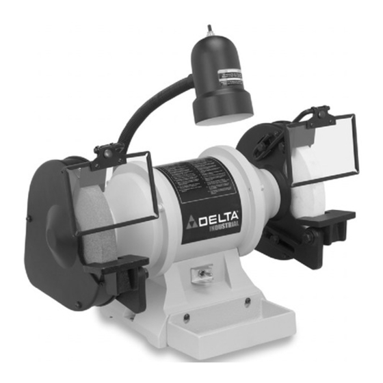
10" Grinder w/Pedestal
8" Grinder w/Pedestal
8" Slow Speed Grinder
In Canada call
(Model 23-735)
(Model 23-730)
(Model 23-725)
PART NO. 900804 (011)
Copyright © 2001 Delta Machinery
1-800-463-3582).
Advertisement
Table of Contents

Subscribe to Our Youtube Channel
Summary of Contents for Delta 23-725
- Page 1 10" Grinder w/Pedestal 8" Slow Speed Grinder To learn more about DELTA MACHINERY visit our website at: www.deltamachinery.com. For Parts, Service, Warranty or other Assistance, 1-800-223-7278 ( please call 8" Grinder w/Pedestal 1-800-463-3582). In Canada call (Model 23-735) (Model 23-730) (Model 23-725) PART NO.
-
Page 2: Safety Rules
If you have any questions relative to a particular application, DO NOT use the machine until you have first contacted Delta to determine if it can or should be performed on the product. -
Page 3: Additional Safety Rules For Grinders
3. USE only grinding wheels rated for 3600 RPM with a 5/8" or 1" arbor hole, for Models 23-730 & 23-725. NEVER use a wheel rated lower than 3600 RPM for Model 23-730, NEVER use a wheel rated lower than 1800 RPM for Model 23-725, or attempt to machine an undersize wheel to fit an arbor. -
Page 4: Unpacking And Cleaning
This coating may be removed with a soft cloth moistened with kerosene (do not use acetone, gasoline, or lacquer thinner for this purpose). Fig. 1 illustrates the components of the grinder. WARNING: FOR YOUR OWN SAFETY, DO NOT CONNECT THE TOOL TO THE POWER SOURCE UNTIL THE MACHINE IS COMPLETELY ASSEMBLED AND YOU HAVE READ AND UNDERSTAND THE ENTIRE INSTRUCTION MANUAL. -
Page 5: Hardware Illustration
HARDWARE ILLUSTRATION Fig. 2 illustrates the hardware components of the grinder. ACTUAL SIZE M10 x 1.50 x 30 M8 x 1.25 x 18 M8 x 1.25 x 15 M8 x 1.25 x 10 M6 x 1.0 x 15 M6 x 1.0 x 18 Fig. -
Page 6: Assembling Tool Rests
ASSEMBLING TOOL RESTS 1. The tool rest arms (F) Fig. 3, are universal and can be attached to either side of the grinder. Assemble adjustable tool rest (J) Fig. 3, to left side of tool rest arm (F) Fig. 3, as shown, and fasten with one bolt (1) Fig. 2, and one washer (7) Fig. -
Page 7: Assembling Eye Shields
Fig. 6 ASSEMBLING EYE SHIELDS Your grinder is supplied with two eye shields for operator protection. NOTE: ALWAYS WEAR EYE PROTECTION. To assemble the eye shields, proceed as follows: 1. Assemble long end of eye shield mounting rod (D) Fig. 1, to the side of each wheel guard using the eye shield rod bracket (E) Fig. - Page 8 Fig. 11, on top of the column. FASTENING GRINDER TO PEDESTAL Place grinder onto pedestal and align bolt hole opening in grinder with bolt hole on pedestal. Place washer (12) Fig. 10, onto bolt (11) Fig. 10, and insert bolt through grinder and pedestal.
-
Page 9: Extension Cords
Your tool is wired for 120 volt, 60 HZ alternating current. Before connecting the tool to the power source, make sure the switch is in the “OFF” position. The motor for the 23-725 & 23-735 provides a no-load speed of 1725 RPM. The motor for the 23-730 provides a no-load speed of 3450 RPM. - Page 10 GROUNDED. IF YOU ARE NOT SURE HAVE A CERTIFIED ELECTRICIAN CHECK THE RECEPTACLE. FLEXIBLE LAMP The flexible lamp operates independently of the grinder. To turn the lamp on and off, rotate switch (A) Fig. 17. WARNING: To reduce the risk of fire, use 40 watt or less, 120 volt, reflector track type light bulb (not supplied).
-
Page 11: Grinding Wheels
Model 23-730 grinders should be rated for 3600 RPM or higher and be 8" in diameter with a 5/8" or 1" arbor hole. Grinding wheels used with Model 23-725 grinders should be rated for 1800 RPM or higher and be 8"... -
Page 12: Changing Grinding Wheels
(C) Fig. 21, and the tool rest (D). NOTE: Facing the front of the grinder: to replace the wheel on the left side of the grinder, turn the arbor nut (E) Fig. 21, clockwise to loosen; counterclockwise to tighten the arbor nut. - Page 13 SHIELDS IN PLACE AT ALL TIMES. Figures 23, 24, and 25, illustrate several typical operations that can be accomplished using the grinder. Each tool rest should be positioned a little below the center of the grinding wheel and adjusted so the edge of the tool rest is as close as possible to the grinding wheel for maximum support to the piece that is being ground.
-
Page 14: Parts, Service Or Warranty Assistance
Two Year Limited Warranty Delta will repair or replace, at its expense and at its option, any Delta machine, machine part, or machine accessory which in normal use has proven to be defective in workmanship or material, provided that the... - Page 15 NOTES...
- Page 16 Parts and accessories for Porter-Cable Delta products should be obtained by contacting any Porter-Cable Delta Distributor, Authorized Service Center, or Porter-Cable Delta Factory Service Center. If you do not have access to any of these, call 888-848-5175 and you will be directed to the nearest Porter-Cable Delta Factory Service Center.


Need help?
Do you have a question about the 23-725 and is the answer not in the manual?
Questions and answers