
Related Manuals for JAI LQ-200CL


Summary of Contents for JAI LQ-200CL
- Page 1 User's Manual LQ-200CL RGB Color & NIR 4CCD Line Scan Camera Document Version:1.5 LQ-200CL_Ver.1.5_Dec2014...
- Page 2 JAI Ltd., Japan and may only be used by the purchasers of the product. JAI Ltd., Japan makes no warranty for the use of its product and assumes no responsibility for any errors which may appear or for damages resulting from the use of the information contained herein.
- Page 3 LQ-200CL Supplement The following statement is related to the regulation on “ Measures for the Administration of the control of Pollution by Electronic Information Products “ , known as “ China RoHS “. The table shows contained Hazardous Substances in this camera.
-
Page 4: Table Of Contents
LQ-200CL - Table of contents – General ......................5 Camera nomenclature ..................5 Main features ....................5 Locations and functions ..................6 4.1. Locations and functions ................6 4.2. Rear Panel ....................7 Connectors and pin assignment ................8 5.1. - Page 5 Serial communication and command list ............... 33 8.1. Serial communication ................. 33 8.2. Command list ..................34 Camera Control Tool for LQ-200CL ..............40 External appearance and Dimensions ..............44 Specifications ..................... 45 11.1 Typical data ....................45 11.2 Camera Spectral sensitivity ................. 47 Appendix ......................
-
Page 6: General
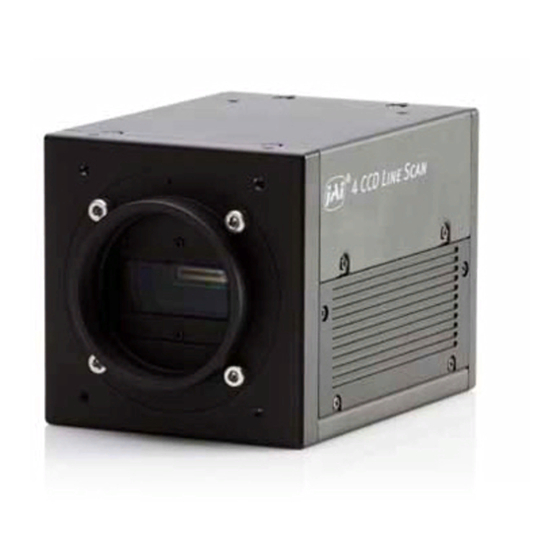
General The LQ-200CL is a 4CCD line scan camera using four 2048 pixel line sensors mounted on a prism, for the R, G,B and NIR channels. It operates with a 40 MHz pixel clock, resulting in a maximum line rate of 19,048 lines per second. -
Page 7: Locations And Functions
LQ-200CL Locations and functions 4.1. Locations and functions Fig. 1 Location of external features 1 Lens mount M52 mount (*1)Note) 2 Camera Link part 1 base connector (1) (*2)Note) 3 Camera Link part2 medium connector (2) (*2)Note) 4 12-pin Hirose connector... -
Page 8: Rear Panel
LQ-200CL 4.2. Rear Panel ① POW ER / TRIG W . B . D C IN ② /TRIG S W 1 Fig2. Rear panel ① LED Green (Steady) Operating, but not receiving external trigger input Green (Flashing) Operating and receiving external trigger input. -
Page 9: Connectors And Pin Assignment
Cables, transmission systems and frame grabbers/acquisition boards that do not comply with the Camera Link standard may work with this camera, but JAI Camera Solutions cannot be held responsible for loss in performance or damage of equipment, including the camera. -
Page 10: Input And Output Circuits
LQ-200CL Connector 2 ( Used only for 4 x 10 Bit output) Pin No In/Out Name Note 1,14 Shield 2(-),15(+) TxOUT0 3(-),16(+) TxOUT1 Data out 4(-),17(+) TxOUT2 5(-),18(+) TxClk Clock for CL 6(-),19(+) TxOUT3 Data out 7(+),20(-) 8(-),21(+) 9(-),22(+) 10(+),23(-) -
Page 11: Camera Link Interface (Bit Allocation)
LQ-200CL 5.3.3 Camera Link Interface (Bit allocation) The LQ-200CL follows the Camera Link standard in all respects. Port/Signal 8bitx4 output 10bitx4 output Connector Pin Name Port A0 Out1_D0 Out1_D0 Port A1 Out1_D1 Out1_D1 Port A2 Out1_D2 Out1_D2 Port A3 Out1_D3... -
Page 12: Camera Link Output Port
Tx25 DVAL Tx26 Tx23 5.3.4 Camera link output port LQ-200CL handles R,G,B and NIR channels. The output ports for 8-bit and 10-bit are different. 8 bit output Input signal Camera link output Out1 Camera Link 1 Port a – c... -
Page 13: Functions And Operation
(the inverse of line rate). This also allows a fixed exposure time, independent of the line rate. In the LQ-200CL the exposure time can be set individually for all four channels. -
Page 14: Operating Mode
LQ-200CL 6.2. Operating mode The LQ-200CL has three operating modes. They are No-Shutter mode, Shutter-Select mode and PWC (Pulse Width Control) mode. The following chapters explain the details of these three modes. The output detail is shown below and is common with all modes. -
Page 15: No-Shutter Mode With Internal Trigger
LQ-200CL 6.2.1 No-Shutter mode with internal trigger In this mode the camera does not accept an external trigger signal, as the line rate is generated from an internal clock (user programmable, command LR). The exposure time is directly proportional to the line rate (T = 1/line rate). -
Page 16: Shutter Mode With External Trigger
LQ-200CL 6.2.2 No-Shutter mode with external trigger In this mode, the exposure time is directly proportional to the line rate. The line rate is generated externally by a trigger signal. This mode is used when an external trigger signal available, e.g. -
Page 17: Shutter-Select Mode With Internal Trigger
LQ-200CL 6.2.3 Shutter-Select mode with internal trigger This mode allows the user to have full control of the line rate and the exposure time individually, by programming separate timing generators. Subsequently, the camera does not accept an external trigger signal in this mode. -
Page 18: Shutter-Select Mode With External Trigger
LQ-200CL 6.2.4 Shutter-Select mode with external trigger This mode allows the user to have full control of the exposure time, by programming a timing generator, while the line rate is controlled by an external trigger signal. The camera can accept an external trigger through the Camera Link connector or though the 12-pin Hirose connector. -
Page 19: Pulse Width Control (Pwc) Mode
LQ-200CL 6.2.5 Pulse Width Control (PWC) mode In this mode, the user has full control of both the line rate and the exposure time of each line via the External Trigger input. At the falling edge of the External Trigger signal, the exposure is initiated, and at the rising edge the exposure is terminated and read out. -
Page 20: Scan Rate And Exposure Time Range
LQ-200CL 6.3. Scan rate and exposure time range 6.3.1 Minimum cycle time of external trigger Mode Minimum trigger cycle No-Shutter C1+52.5μs Shutter-Select C1+52.5μs Exposure + C2 C1 =0.1μs; C2= 52.6μs 6.3.2 Minimum trigger pulse width. Mode Via Camera Link Via Hirose 12-pin... -
Page 21: Functions Listed Alphabetically By Command Acronyms
Settings 0 (off) and 1 (on). Factory default is 0 (off). In this mode, when a trigger pulse does not occur after more than 53ms, the LQ-200CL automatically returns to continuous operation with the line rate of 52.5μs. In this time, the camera operates by the internal trigger, and if the trigger is input, the video is immediately output. -
Page 22: Command Ah - Activate One-Push Auto White Balance (Awb) - Shutter
LQ-200CL Command AH - Activate One-Push Auto White Balance (AWB) - Shutter By sending this command via the serial communication, the shutter based One-Push AWB function is activated. The white balance function takes approximately 3 seconds to complete. During this time the rear panel LED will show orange. -
Page 23: Command Bi - Binning (Horizontal Only)
0 LSB to 64 (16) LSB. The number in parenthesis is valid for 32-bit output. The LQ-200CL has an automatic black level clamp function. This circuit is an analog circuit and after the signal level of dummy pixels is clamped at the constant level, it is digitized and the OB level is clamped at 32 LSB (8 LSB) in the digital clamp circuit. -
Page 24: Command Ei - Interlocked R, G, B & Nir Exposure
LQ-200CL 7.12 Command EI – Interlocked R, G, B & NIR Exposure When this function enabled (interlocked), exposure time for all four channels is selected by setting the green channel and the red, blue and NIR channels will track. To obtain white balance, adjust red and blue channels, PER and PEB. It is thereafter possible to adjust overall exposure time by using the command PEG. -
Page 25: Commands Gar2 , Gag2, Gab2 And Gair2 - Fine Gain (R,G, B And Nir)
It is recommended to use 52.5μs to 2ms of line rate because the black level is stable in this range. 7.18 Command LUTC - LUT Control The LQ-200CL has an internal LUT(Look Up Table) for setting gamma. Command LUTC selects gamma OFF, Gamma 0.45 or LUT. Settings: 0 = Off 1 = 0.45... -
Page 26: Command Nr - Noise Reduction
LQ-200CL γ=User In this mode, R,G,B or NIR can be set individually. Settings: Range: 0 to 8191 LSB (200%) Setting point: 512 Setting point 7.19. Command NR - Noise Reduction Noise levels less than 16 LSB (4LSB) which are superimposed on the video signal will be eliminated. -
Page 27: 7.22. Command Pbs - Request Status After Pixel Black Correction
LQ-200CL Principle of Pixel black level correction (DSNU / FPN correction) Dark Signal Non-Uniformity or Fixed Pattern Noise is, as the name implies, fixed pattern on the sensor output, which is not dependent on the incoming light. Before correction: dark signal non-uniformity from pixel to pixel... -
Page 28: Command Pgc - Enable Flat-Field Correction (Pixel Gain)
LQ-200CL 7.24. Command PGC – Enable Flat-Field Correction (pixel gain) This command enables (or disables) the “pixel gain” (flat-field) correction function, which compensates for Pixel Response Non Uniformity (PRNU) for individual pixels. The algorithm for compensation is different in No-Shutter mode and Shutter-Select mode. -
Page 29: 7.26. Command Pgs - Request Status After Pixel Gain Correction
LQ-200CL Before correction: Non-uniform response from Multiply pixel to pixel Factor Average < 1 Multiply Factor > 1 To correct for PRNU, the camera’s internal correction circuit captures one or several lines of data under non-saturated illuminated conditions (not more than 80% of maximum - recommend level is half of maximum), and the average across the line is calculated. -
Page 30: 7.27. Command Sdc - Select Shading Correction Mode
LQ-200CL 7.27. Command SDC – Select Shading Correction Mode This function enables (or disables) shading correction. Settings: 0 = off (Bypass) (Default) 1 = Factory setting 2 = User area Associated functions: Commands PGR, SDR and SDS 7.28. Command SDR – Run Shading Correction This function initiates automatic shading correction, and stores the result to the user area. -
Page 31: Command Sds - Request Status After Executing Shading Correction Command
LQ-200CL Shading correction tracking the green channel Note: For this function, no reference value is stored in the camera. Operating procedure for individual R, ,B and NIR channel shadings correction: 1. Before making adjustment, approximately 30 minutes of warm up is required. -
Page 32: Command Tp - Trigger Polarity
LQ-200CL Fig. 21 Rear panel DIP-switch 7.32. Command TP – Trigger Polarity Settings: 0=Active Low (factory default) 1=Active High 7.33. Command TR – Trigger Mode Selects the trigger mode of the camera. Depending on the mode used, it allows the scan rate to either be programmed by an internal timing generator or by and external trigger pulse. -
Page 33: Command Wb - White Balance
LQ-200CL 890 (222) 10bit (8-bit) Signal (RGB) 32 (8) 10bit (8-bit) 2048 Pixel count Fig. 17 Gray wedge test pattern 890 (222) 10bit (8-bit) Signal (RGB) 32 (8) 10bit (8-bit) 2048 Pixel count Fig. 18 Gray bars test pattern 890 (222) -
Page 34: Serial Communication And Command List
8.1. Serial communication The LQ-200CL can communicate by serial communication via the Camera Link connector or via RS232C in the 12-pin Hirose connector. The Baud Rate is fixed at 9600 bps. Switch SW1 at the rear panel of the camera is used to select which way the serial communication is set up. -
Page 35: Command List
LQ-200CL Note: HIROSE 12 Pin and Camera Link can not be used simultaneously. Communication setting: Baud Rate 9600 Data Length 8bit Start Bit 1bit Stop Bit 1bit Parity Xon/Xoff Control Protocol. Transmit setting to camera: NN=[Parameter]<CR><LF> (NN is any kind of command. Capital or small letters.) The camera answers: COMPLETE<CR><LF>... - Page 36 LQ-200CL Returns character EB=[Param.]<CR><LF> Echo Back 0=Echo off, 1=Echo on sent to the camera. EB?<CR><LF> Off at power up Display current Camera Status ST?<CR><LF> settings of all Request functions Online Help Get a list of HP?<CR><LF> Request available commands Firmware...
- Page 37 LQ-200CL 1=AWB has not been finished yet. 2=Error1. Green image was too bright. 3=Error2. Green image was too dark. 4=Error3. Timeout-error occurred. C - Trigger mode 0=No-Shutter mode TR=[Param.]<CR><LF> 1=Shutter-Select mode Trigger Mode TR?<CR><LF> 2=Pulse Width Control mode TG=[Param.]<CR><LF> 0=Internal...
- Page 38 LQ-200CL Black Level - BLIR=[Param.]<CR><LF> Master Tracking:-128 to 127 BLIR BLIR?<CR><LF> Individual:0 to 255 BLM=[Param.]<CR><LF> 0=Master Tracking BLM Gain Mode Default is 0 BLM?<CR><LF> 1=Individual 0=Manual/One push AWB WB=[Param.]<CR><LF> 1=4000K White Balance WB?<CR><LF> 2=4600K 3=5600K Activate One- AW=[Param.]<CR><LF> 0=Activate one-push AWB push AWB <Camera replies >...
- Page 39 LQ-200CL area 1=Run color shading correction, store to user area 0=Shading correction not yet completed. Inquire the 1=Succeeded. status after SDS?<CR><LF> 2=Error 1 – Image too bright shading 3=Error 2 - Image too dark correction 4=Error 3 - Timeout error occurred.
- Page 40 LQ-200CL...
-
Page 41: Camera Control Tool For Lq-200Cl
Open the Control Tool Connect the camera to the PC on which the software is installed and set the power ON. Then select “All programs” in the Windows start menu, select “JAI A-S” and click “LQ-200CL control tool”. LQ-200CL Camera Control Tool and Communication windows will open. - Page 42 LQ-200CL 9.4. Camera control window When the connection between camera and PC is completed, the camera control tool shows the current camera settings. 9.5. LUT setting Open the drop-down menu under “LUT” and click “User”. When you click “LUT setting”, the following four windows for NIR, Red, Blue and Green will be...
- Page 43 LQ-200CL When you drag the line and move it, the required gamma characteristics can be obtained. 9.6. Menus 9.6.1 File menu Open: Transfer the setting parameters in HDD or other memory devices to the camera. The extension is .cam Save as: Store the setting parameters in HDD other memory devices.
- Page 44 LQ-200CL 9.5.4 Gamma menu Open Data file: Transfer the LUT data stored in HDD or the other memory devices, to the Control software. The file extension is .csv. Save Data to File: Store the LUT data set in the Control software, to HDD or other memory devices.
-
Page 45: External Appearance And Dimensions
LQ-200CL External appearance and Dimensions Fig.26 External Appearance and Dimensions... -
Page 46: Specifications
LQ-200CL Specifications 11.1 Typical data Scanning system Line Scan Effective pixels : 2048 pixels Image Sensor Pixel Size : 14.0μm × 14.0μm Effective image length : 28.672mm Pixel clock 40.00 MHz Line rate: 52.5 μs (No-Shutter mode with internal trigger) - Page 47 LQ-200CL Flat shading compensation, Color shading compensation 3. Color matrix : R,G,B color compensation 4. LUT/Gamma : OFF, 0.45 and User settings 5. Noise reduction Operation mode No-Shutter, Shutter-Select, Pulse Width Control (PWC) Hirose 12-Pin : 4.0±2.0Vp-p TTL or Camera Link : LVDS (CC1)
-
Page 48: Camera Spectral Sensitivity
LQ-200CL Refer to chapter 5. Connectors. 11.2 Camera Spectral sensitivity LQ-200CL Spectral Response NIRch 1000 1100 wavelength(nm) Fig. 27 Camera Spectral sensitivity... -
Page 49: Appendix
LQ-200CL Appendix Precautions Personnel not trained in dealing with similar electronic devices should not service this camera. The camera contains components sensitive to electrostatic discharge. The handling of these devices should follow the requirements of electrostatic sensitive components. Do not attempt to disassemble this camera. -
Page 50: Caution When Mounting The Camera
Attaching the tripod mount Exportation When exporting this product, please follow the export regulation of your own country. References 1. This manual and datasheet for the LQ-200CL can be downloaded from www.jai.com 2. Camera control software can be downloaded from www.jai.com... -
Page 51: Change History
LQ-200CL Change history Date Revision Changes May 2010 New release June 2010 The rear protrusion of M52 mount lens is changed from 14mm to 13mm. (Page 6 and 45) June 2010 Update the spectral response March 2011 Correct the description of the shading compensation on page NIR channel is also included. -
Page 52: User's Record
Company and product names mentioned in this manual are trademarks or registered trademarks of their respective owners. JAI A-S cannot be held responsible for any technical or typographical errors and reserves the right to make changes to products and documentation without prior notification.
Need help?
Do you have a question about the LQ-200CL and is the answer not in the manual?
Questions and answers