
Related Manuals for HygroMatik DDS Series


Summary of Contents for HygroMatik DDS Series
- Page 1 Steam Injection Humidifiers DDS FlexLine for existing steam systems MANUAL ÁDDS.ENZÈ DDS.EN E-8881128...
- Page 2 Copyright © HygroMatik GmbH [19.07.2021] Steam Injection Humidifiers / DDS EN Information in this manual is subject to change or alteration without prior notice. WARNING Risk of electrical shock! Hazardous electrical high voltage! All electrical work to be performed by certified expert staff (electricians or expert personnel with eqivalent training) only.
-
Page 3: Table Of Contents
1. Introduction ........................5 1.1 Typographic Distinctions ....................5 1.2 Documentation ........................5 1.3 Symbols in Use ......................... 5 1.3.1 Specific Symbols related to Safety Instructions ............. 5 1.3.2 General Symbols ......................5 1.4 Intended Use ........................6 2. Safety Instructions ......................7 2.1 Guidelines for Safe Operation ................... - Page 4 7.4 Separator ........................... 29 7.5 Control Valve and Actuator ....................29 7.6 Pneumatic Start-up safety feature ..................30 7.7 Steam Lances ........................30 7.7.1 Duct mounting set for steam lance ................. 31 7.7.2 Installation Examples ..................... 32 7.8 Steam Lance Heating System ................... 35 7.9 Check List ..........................
-
Page 5: Introduction
1. Introduction Versions in Other Languages Dear Customer, These operating instructions are available in Thank you for choosing a HygroMatik steam several languages. If interested, please con- injection humidifier. tact HygroMatik or your HygroMatik dealer. HygroMatik steam humidifiers represent the latest in humidification technology. -
Page 6: Intended Use
Improper use: Proper usage also comprises the adherence Any other use not compatible with the to the conditions specified by HygroMatik for: intended use outlined above is not allowable. • installation Improper use as well as changes in hardware •... -
Page 7: Safety Instructions
2. Safety Instructions These safety instructions are required by law. They promote workplace safety and accident Risk of material damage! prevention. The unit may be damaged if switched on repeatedly following a malfunction without 2.1 Guidelines for Safe Opera- prior repair. tion Rectify defects immediately! 2.1.1 Scope... -
Page 8: Mounting, Dismantling, Maintenance And Repair Of The Unit
• Steam pipes are hot and care must be Do not install HygroMatik steam generators taken accordingly. above electrical equipment such as fuse • Use only steam without chemical addi- boxes, electrical appliances, etc. -
Page 9: Disposal After Dismantling
Promptly repair any dam- age such as loose connections or burned wiring. • Responsibility for intrinsically safe installation of the HygroMatik steam humidifiers is incumbent on the install- ing specialist company. Disposal after dismantling The humidifier is made up of metal parts and plastic parts. -
Page 10: Transport
3. Transport 3.4 Check for Complete and Cor- rect Delivery of Goods 3.1 Overview Upon receipt of the unit, confirm that: Please note • model and serial number on the name plate match those specified in Proceed carefully when transporting the the order and delivery documents steam injection humidifier in order to prevent damage due to stress or careless loading... -
Page 11: Function And Assembly
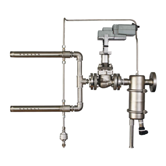
4.1 Areas of application over the Separator interface (2) into the Separator (3). The separator separates con- The typical use of the HygroMatik DDS pres- densation from the steam. surized steam humidifier is for supply air humidification. The system is connected to... - Page 12 SIH Version C (Material Mix) SIH Version C (MaterialMix) 7- control valve 1 - dirt particle trap 8 - Steam lance (s) 2 - Separator interface 9 - Nozzles 3 - Separator 10 - Thermic Capsule Condensation Drain 4 - Float controlled Condensation Drain 11 - Operation switch 5 - Start-up safety feature 12 - steam lance heating system...
-
Page 13: Components
4.3 Components Function The HygroMatik pressure steam humidifier Steam flows through the pipe union (1) into consists of 4 basic elements: the separator. • Seperator Steam and condensate are separated by the • Control valve with or without actuator joint action of the inlet pipe (2) and the spi- ral-shaped flow system. -
Page 14: Strainer
Standard are the Spirax-Sarco Valves from HygroMatik. Alternative suppliers can be listed on application. Control valves ARI type BR440 SIH Type A Principle description... - Page 15 Ohm parallel) resistor is connected to over connec- tors 1 and 3. The resistor is attached under the cover. Typ Hygromatik E- 4111680 Typ Spirax Sarco PN9000 Pneumatic Actuator Pneumatic Actuators are controlled using compressed air (e.g. 0,2-1barg). Compressed air is supplied over a com- pressed air supply (3) to a diaphragm (2).
-
Page 16: Start-Up Safety Switch
4.3.4 Start-up safety switch The start-up safety switch ensures that no condensate from the steam network has relief valve entered the air conditioning duct over the steam lances. capillary tube screw 1/2” temperature sensor electrical Start-up safety switch E-4111952 If no start-up safety switch is available it is advisable to let the unit run a few minutes Electrical Start-up safety switch before switching the control on. -
Page 17: Steam Lances
4.3.5 Steam Lances Number of steam lances The steam lance system may comprise multi- In the steam lances dry steam is blown out of ple steam lances. specially formed nozzles. They are designed for low noise steam emission. The nozzles With a duct height of more than 1000 mm take steam from the driest area in the steam multiple lances should be positioned horizon-... -
Page 18: Pressure Gauge Station
Steam lance piping for multiple steam lances. Pressure gauge shut-off valves and siphons are available on request. HygroMatik standard supply is for lengths of 300 mm and 450 mm. Distances are approximate and can vary from installa- tion to installation. Piping should be... -
Page 19: Ball Float Steam Trap
4.3.7 Ball Float Steam Trap After separation from the steam inside the separator condensate is drained out through a ball float steam trap. Function The discharge valve is controlled by the ball float dependent upon the density of the incoming medium. Please note During installation, it is important to ensure that the marking "TOP"... -
Page 20: Thermostatic Capsule Steam
4.3.8 Thermostatic Capsule Steam Condensate that has collected in the steam lance heating system is discharged through a Do not insulate the thermic capsule steam thermostatic capsule steam trap. trap. Function The minimum connection pipe length of 1.0 m (L3) between the lance connection and The discharge valve is controlled dependent the drain is absolutely mandatory. -
Page 21: Humidification Output
5. Humidification Output flow figure [m³/h] The maximum humidification output [kg/h] of Valve coefficient [m³/h] one steam injection unit depends upon the available steam pressure in barg. Example: Maximum humidification output can be more Desired humidification output: 110 kg/h than 770 kg/h (Type A) or 730 kg/h (Type C). Operating pressure, p = 2 barg Maximum operating pressure is pmax = 4,5 barg. -
Page 22: Separator Type 20 With One Steam Lance
5.3 Separator Type 20 with one Please note steam lance The following 4 graphs show Kvs -Values determination. KVS-Value [m³/h] Pressure [barg] Page 22... -
Page 23: Separator Type 20 With Multiple Steam Lances
5.4 Separator Type 20 with multiple steam lances KVS-Value [m³/h] Pressure [barg] Page 23... -
Page 24: Separator Type 40 With One Steam Lance
5.5 Separator Type 40 with one steam lance KVS-Value [m³/h] Pressure [barg] Page 24... -
Page 25: Separator Type 40 With Multiple Steam Lances
5.6 Separator Type 40 with multiple steam lances KVS-Value [m³/h] Pressure [barg] Page 25... -
Page 26: Graph For Determing Absorption Distance
6. Graph for Determing Absorption Distance Page 26... -
Page 27: Mechanical Installation
During installation, the unit must be discon- nected from power supply and secured • By design, HygroMatik steam humidifi- against being switched on again. The ers are not qualified for outdoor instal- absence of voltage must be ensured by a lation (electronical components and measurement. -
Page 28: Water Hammer Prevention
7.3 Water hammer prevention WARNING HygroMatik recommends the installation of a shut-off valve in front of the steam injection Water hammers are dangerous and can system in order to facilitate any necessary cause bodily harm. maintenance work. It is necessary to drain off any low angles in... -
Page 29: Separator
7.4 Separator 7.5 Control Valve and Actuator If the valve is part of the on-site installation, the necessary connection fittings between control valve and the separator come • Before installation, check out the steam attached to the separator. All other parts are supply piping. -
Page 30: Pneumatic Start-Up Safety Feature
HygroMatik can supply stainless steel stand- ard modules for lance pitches of 300 and 450 The distance between lance and duct ceil- ing or floor should be a minimum of 200 Before the lance is installed in the duct check that the correct lance is present. -
Page 31: Duct Mounting Set For Steam Lance
7.7.1 Duct mounting set for steam lance In order to prevent steam condensing on the duct inner walls the lances should be After the lance is positioned, an angle is posi- installed according to the following dimen- tioned on the opposite duct wall side at the sions: same height. -
Page 32: Installation Examples
Lance guide is installed in the following After the lance has been installed the gap manner: between duct outer wall and lance is closed using the two cover plates as supplied with » feed bar through hole in angle the steam lances. The cover plates are »... - Page 33 Position lances in the duct centre if possible. If the humidifier blows into a compact multi- zone unit then it should be installed directly in the air flow and as close as possible to the fan. The bifurcated pipe should never be installed less than one meter in front of the fan suction side.
- Page 34 When selecting the lance choose a size suffi- cient for the entire duct width or height. If the ducting is taller than it is wide, install the steam lance vertically. If this is not possible then a second lance must be installed in order to ensure an even steam distribution.
-
Page 35: Steam Lance Heating System
7.8 Steam Lance Heating System Installation of the steam lance heating sys- tem follows the installation of the steam injec- tion system including steam lances. WARNING accordance with the dimensions of the humidifier unit a pipe with an external dimen- The line to the heating system must be able to sion of 8mm is bent to shape and installed tolerate pressures of up to maximum 8 barg. -
Page 36: Check List
7.9 Check List The steam injection humidifier may only be operated by qualified and authorised person- nel. Before switching on the steam injection humidifier please check for correct installa- tion by going through the following check list: • Have the steam supply lines been flushed out? •... -
Page 37: Electrical Connection
• Electric connector cables to be laid pro- fessionally Wiring diagram for HygroMatik actuator • Install the electrical connections according to the wiring diagram Possible electronical components de- struction through electrostatical dis-... -
Page 38: Commissioning
9. Commissioning Turning the steam injection humidifier on Risk of operating error! Start-up of the unit is restricted to expert staff If the actuator is not a controlled actuator only. then verify that the control valve is in the For actuator initial operation please refer to closed position. - Page 39 Periodic filter cleaning is recommended in order to prevent the control valve from exces- sive wear. Before cleaning the filter always shut off the steam supply and allow the sys- tem to cool down. The following operations are active: • Accumulated condensate in the steam supply is forced into the separator where it is fed into the condensate net-...
-
Page 40: Maintenance
10. Maintenance 10.1 Strainer The HygroMatik steam injection humidifier is Maintenance „SIH Type A“ easy to maintain. However, inadequate or improper maintenance can lead to opera- » Loosen the screws (M12/M16) on tional malfunctions. Regular maintenance is the flange connection (D) at the essential so that your steam injection humidi- steam entry point. -
Page 41: Ball Float Condensate Drain
10.2 Ball float condensate drain Maintenance „SIH Type C“ » Unscrew filter holder (C) , (SW27 or SW50). Maintenance „SIH Type A“ » Extract filter (B) and clean or » Release condensate drain from replace. separator. » Replace seal (A). »... -
Page 42: Malfunctions
11. Malfunctions Problem Possible Cause to do No steam is coming • Defective Hygrostat or humidity sensor • Check Hygrostaten and/or humility sensor and repair or out of steam lance replace as necessary. • Defective Control Valve • Check valve and clean it or replace as necessary. - Page 43 Problem Possible Cause to do Condensate is com- • Steam trap drain is considerably • Install condensate drain higher that the SIH system. beneath the humidifier level and ing out of steam pump out the resultant conden- lance. sate to a suitable place. •...
-
Page 44: Dimensions And Installation Schematic
12. Dimensions and Installation Schematic Steam Injection System Type A (stainless steel) Steam Injection System Type C (mixed materials) DDS20 A DDS40 A DDS20 C DDS40 C [mm] [mm] [mm] [mm] 310…330 440...500 420…440 660…700 one lance system multiple lance system one lance system multiple lance system 300 / 450... - Page 45 Page 45...
-
Page 46: Spare Parts
13. Spare Parts Type A Type C Model Model Article Number Description Separators E-4111252 Separator, without additions E-4111254 Separator, without additions B-4500001 Separator DDS20 incl. ball float steam trap and dirt trap B-4500003 Separator DDS40 incl. ball float steam trap and dirt trap B-4111917 maintenance set DDS20 Version A (encloses: seals, dirt trap) B-4111919... - Page 47 PP5, complete with 1 x 2barg and 1 x 7barg For ordering spare parts, a template can be found on the www.hygromatik.com website under the „Contact“ tab. Your spare parts order may as well be directed per e-mail to the HygroMatik main office using the address hy@hygromatik.de.
- Page 48 This page intentionally left blank Page 48...
- Page 49 This page intentionally left blank Page 49...
-
Page 50: Technical Data
14. Technical Data Technical Data Seperator DDS 20 DDS 40 Version Thread connections 1/4“ 1/2“ inner thread 1/2“ external thread 1/2“ external thread 1" inner thread 3/4“ external thread 1 1/2" inner thread 1 1/2" external thread DN 25 Flange 3/4“... - Page 51 Technical Data Steamlances Type 20 Type 40 Lancecode h (mm) j (mm) Weight (kg) h (mm) j (mm) Weight (kg) 0,88 1,54 1,14 1,97 2,39 3,03 1148 1268 2,26 1148 1275 3,78 1408 1528 2,65 1408 1535 1718 1838 3,11 1718 1845 5,15...
- Page 52 Lise-Meitner-Str.3 • D-24558 Henstedt-Ulzburg Phone +49(0)4193/ 895-0 • Fax -33 eMail hy@hygromatik.de • www.hygromatik.com member of CAREL Group Ein Unternehmen der Gruppe 100%...
Need help?
Do you have a question about the DDS Series and is the answer not in the manual?
Questions and answers