Table of Contents
Advertisement
Quick Links
Advertisement
Chapters
Table of Contents

Related Manuals for HygroMatik DBV66P


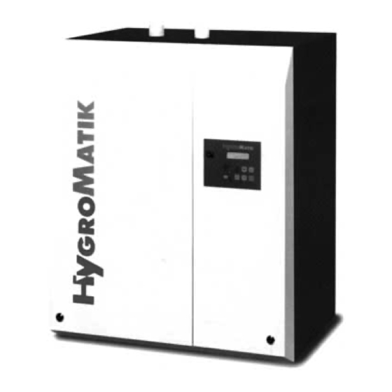
Summary of Contents for HygroMatik DBV66P
- Page 2 Text written in the Arial Italic font refers eather exclusively or additionally to operation with the DBV Universal for use with tap water Copyright HYGROMATIK Lufttechnischer Apparatebau GmbH 2002 i DBV P2 e 0212 Information in this manual is subject to change or emendation without prior notice.
-
Page 3: Table Of Contents
Electric Heater Steam Humidifiers Series DBV66P - DBV526P for use with fully demineralised water or purified condensate Series DBV-U66P - DBV-U526P for use with tap water Operation and Maintenance Instructions Operating Instructions Introduction ............................3 1.1.1 Operating Instructions.......................... 3 1.1.2 Typographic Distinctions........................ - Page 4 1.15 Parameter Description ........................14 1.16 Language/Sprache........................... 17 1.17 Faults Events ........................... 17 1.18 System Test............................17 1.19 Interface (Optional).......................... 19 1.20 Faults ..............................20 1.21 Maintenance............................. 25 1.21.1 Maintenance when using Demineralized Water / Condensate............25 1.21.2 Maintenance when using Tap Water ....................25 1.21.3 Cleaning the Steam Cylinder ......................
-
Page 5: Introduction
Only qualified and authorised personnel may 1.1 Introduction operate the unit. Persons transporting or working on the unit, must have read and understood the The HYGROMATIK steam humidifier is our answer corresponding parts Operation to today’s technical requirements. It satisfies them... -
Page 6: Disposal After Dismantling
Observe the accident prevention regulations: 1.3 Transport "Electrical installation electrical equipment" (VBG 4) or equivalent national codes. 1.3.1 General In this way you can prevent injury to yourself or Transport the steam humidifier carefully. Prevent others. damage from careless loading and unloading and avoid the use of unnecessary force. -
Page 7: Function And Installation
1.4 Function and Installation 1.4.2 Installation and Procedures 1.4.1 Function Water is admitted through the solenoid valve (14) when the hygrostat or controller calls for humidity. The Electric Heater Principle The solenoid valve is designed for pressures from 0.2 to 10 bar. One, two or three heaters are arranged in a closed Solenoid valves for lower pressures are available cylinder and connected to an AC voltage. -
Page 8: Control Dbv- (U)P
Steam production begins within a few minutes. 1.4.3 Control DBV- (U)P The HYGROMATIK control type DBV-P2 can be The water level in the cylinder is maintained by the programmed for the following control modes. middle level sensor. If the water level goes below Parameter U6 Control has to be set according to the sensor "operational"... -
Page 9: Internal Output Adjustment
Then the following functions are taking place: 1.4.4 Internal Output Adjustment • Display shows: Control of the DBV-(U)P steam humidifier is done Hygromatik ® by proportional control of one of the heating DBV-P2 SW Vers. x.y. elements and phased addition of further heating elements. -
Page 10: Steam Output Limitation
The DBV Universal for use with tap water can be programmed for a moderately extended specific maintenance blow-down interval (see chapter 1.21.2 "Maintenance when using Tap Water"). In this case please contact HYGROMATIK. Manual Drain: % % % % & & & &... -
Page 11: Dbv-(U)P Display And Operating Panel
Other information and functions can be called up 1.7 DBV-(U)P Display and by the panel keys. Operating Panel The operator panel keys can be used for menu functions and parameter alterations as follows: Key Functions Back to previous menu level Humidification L1 = 40,5 kg/h Cursor left... -
Page 12: Fault Messages
Dry Level Blow-down Fault The control type DBV-(U)P periodically activates If the water level in the steam cylinder matches the the pump to drain the cylinder water and smaller dry level, the controls reports Dry Level. pieces of granular materials. If during the set blow-down time the cylinder water Stand-by Blow-down level does not reach the “Dry Level”, the control... -
Page 13: Dbv-P - Menu
1.10 DBV-P - Menu L 7* L8** Fault 8 Fault 7 L9** F ault 1 P 4* F ault 6 F ehler-H isto rie Settings Fault 2 P aram eter Fault 5 S ystem T est F au lt 3 Param eter S ettings Settings... -
Page 14: Control Name Plate
Example: The relative humidity set value should 1.12 Control Name Plate be changed from 50 %RH. to 70 %RH. The display can show 6 different sets of unit data. Attention: internal software Control Name Plate controller must be activated (Parameter U6). -
Page 15: Parameter Settings Using Code
1.14 Parameter Settings using Parameter Description Code Blow-down counter [1 - 25500 kg] Blow-down time [sec] The control type DBV-(U)P is equipped with a Report logic modern computer chip. The external, non-volatile positive / negative data storage device allows operating parameters to Blow-down On/Off be altered, adjusted and stored. -
Page 16: Parameter Description
↵ ↵ ↵ ↵ % % % % ≈ Confirm selection with ≈ Press & & & & until the display shows Cursor appears under first figure. parameter "Control Signal (E3)": Code Control Signal P0 = >000< E3 = 0 - 10 Volt ↵... - Page 17 Calibration Sensor (E4) Humidity [% RH] This parameter allows the calibration of the active humidity sensor connected to terminals 3 - 5. Potential free Signal Outputs (E5/E6) 0-20 mA, P4 = 0% Different humidifier operational reports may be signalled by three built in relays and their potential free contacts.
- Page 18 $ $ $ $ Report logic (H3) Note: If the setting of parameter report logic (H3) is changed, the unit has to be This parameter determines the switching logic of re-started. the potential free relays (terminals 28 - 36). Refer to the following table.
-
Page 19: Language/Sprache
1.16 Language/Sprache 1.18 System Test This menu is used to select the desired system This menu is used to test various system functions language. (e.g. during system commissioning). Language / Sprache The following test routines are available: English System Test German (Deutsch) LED Test French (Francais) - Page 20 Signal-Test Demand Test This tests the connected signals (terminals 3 - 8 This tests whether the safety chain is closed. When built in the unit). The Signal Test is useful, if using the control mode with external or internal parameter "Control" (U6) is set to "internal PI- controller the control demand function is also controller"...
-
Page 21: Interface (Optional)
Pin allocation 2 TxD 3 RxD 5 Gnd $ $ $ $ Note: Please contact HYGROMATIK for the correct syntax for these commands. RS485: The optional interface RS485 is equivalent to the American EIA standard. Preferable use twisted pair cable for data transfer. -
Page 22: Faults
1.20 Faults Switch off the steam humidifier immediately if a fault occurs. Faults are only to be remedied by qualified personnel following the proper safety instructions. Fault Causes Measures • Blow-down pump does not receive Blow-down Fault Check whether relay on the pcb electrical power. - Page 23 See chapter 2.6 "Installation Examples“. − Steam hose installed sags. Lengthen drain hose. Contact − Pressure in duct too high. HYGROMATIK if necessary. (Maximum duct pressure 1500 Pa) • Humidity sensor or connection cable Check humidity sensor and Fault RH Sensor defective.
- Page 24 − Pressure in duct too high. See chapter 2.4 "Installation Examples“. (Maximum duct pressure 1500 Pa) − Lengthen drain hose. Contact HYGROMATIK if necessary. • No steam produced The humidifier switches off at a Increase set value, if necessary. (controller)signal below 20 % and on again Display shows: at 25 %.
- Page 25 Fault Causes Measures • The safety interlock system has been No steam produced. Look for failing function and remedy. triggered. Insert a bridge between the terminals 1 and 2 on the terminal Display shows Stand block. • If a proportional controller is fitted, but Note: Running "Sensor Insert a bridge between the there is no safety system, the absence of a...
- Page 26 See chapter 2.6 "Installation Examples“. Permanently there is Pressure in duct too high • water being drained (Maximum duct pressure: 1500 Pa) Lengthen drain hoses. from the outlet. Pump is Please contact HYGROMATIK, if not operating. necessary. 1.24 DBV-(U)P...
-
Page 27: Maintenance
1.21 Maintenance Cycle Maintenance Work The HYGROMATIK steam humidifier is largely Visual inspection of electrical 4 weeks after maintenance free. Nevertheless, operational faults and mechanical components, commissioning can occur, which have to do with insufficient or cables, connections, etc. improper maintenance. With proper maintenance... - Page 28 Cyclical blow-downs with subsequent fresh tap water filling - and supported by the HYGROMATIK SUPER FLUSH system and a high performance drain pump - remove most of these elements.
-
Page 29: Cleaning The Steam Cylinder
1.21.3 Cleaning the Steam Cylinder Max. Level Operational Level Dry Level Disassembly Attention: Wait some minutes after ≈ Switch on humidifier with the control switch. operation, because steam cylinder could ≈ Drain residual water in the cylinder. Press be still hot. simultaneously on the control % % % %... -
Page 30: Replaycing Heaters And Cut-Outs
≈ Insert a new solvent-free, moistened sealing HYGROMATIK o-ring into the cylinder base. ≈ Remove o-ring from the upper part of the cylinder. ≈ Insert a new solvent-free, moistened HYGROMATIK o-ring into adapter (2). ≈ Refit cylinder into adapter (11). -
Page 31: Cleaning The Pump
≈ Reassemble the pump. release button for Entsperrknopf für Thermowächter ≈ Insert moistened o-ring (3) in the cylinder base thermal cut-out lateral opening. ≈ Insert pump into cylinder base and fasten pump with screws (7). thermal cut-out Thermowächter sealing Dichtung ≈... -
Page 32: Check Cable Connections And Heater Cables
≈ Remove capacity limiter (4) in the inlet and clean 1.21.7 Check Cable Connections and (only DBV-P). Heater Cables ≈ Check all connections to be firmly tightened. Attention: Loose cable connections lead to excessive contact resistance and overheating of the contact surface. 1.21.8 Check Heating Element thermic cut-out Switches Check overheat switch with empty cylinder. -
Page 33: Access Electric Compartment
1.21.9 Access Electric Compartment 1.21.10 Checking Operation The control is attached to a mounting plate, which Start the steam humidifier and operate for a few in turned is fastened with two screws at the divider minutes at maximum output if possible. plate between electric and steam compartment. - Page 34 Electric Heater Steam Humidifiers Series DBV-66P - DBV-526P for use with fully demineralised water or purified condensate Series DBV-U66P - DBV-U526P for use with tap water Operation and Maintenance Instructions Installation Installation ............................2 Steam Humidifier..........................2 2.1.1 Equipment Dimensions DBV-(U)66P - DBV-(U)266P ................3 2.1.2 Equipment Dimensions DBV-(U)306P - DBV-(U)526P .................
-
Page 35: Installation
Additional equipment may not be installed inside unit without prior written consent HYGROMATIK. 2.1 Steam Humidifier ! ! ! ! Note: Be aware of the following when selecting the steam humidifier installation ! ! ! ! location. Note: To function properly the steam humidifier must be installed vertically. -
Page 36: Equipment Dimensions Dbv-(U)66P - Dbv-(U)266P
2.1.1 Equipment Dimensions DBV-(U)66P - DBV-(U)266P DBV-(U)66 - DBV-(U)266 Cable entry W ater supply Thread bolt M5 for W ater drain potential equalisation all dimensions in mm 12,5 Steam outlet Condensate return DBV-(U)P... -
Page 37: Equipment Dimensions Dbv-(U)306P - Dbv-(U)526P
2.1.2 Equipment Dimensions DBV-(U)306P - DBV-(U)526P DBV-(U)306 - DBV-(U)526 Cable entry Thread bolt M5 W ater supply Water supply for potential Water drain Water drain equalisation 435,5 all dimensions in mm Steam Steam outlet outlet Condensate Condensate return return DBV-(U)P... -
Page 38: Fan Unit (Option)
ca. 20 2.2 Fan Unit (option) min. 3000 ! ! ! ! Note: The fan unit should be positioned such that draught effects are avoided. A steam minimum height of 2 m is generally sufficient. • Install the fan unit directly on a wall. Type Fan Unit* DBV-(U)66... -
Page 39: Installation
• The steam hose diameter may not be smaller mm if the steam manifold is turned to an angle of than the steam outlet of the HYGROMATIK 30 - 45° to the direction of the air flow. steam humidifier (do not restrict the cross- section, otherwise back pressure will increase). -
Page 40: Pressure Equalisation
If the steam manifold is positioned lower than 2.4.1 Pressure Equalisation 500 mm above the steam humidifier: Rapid pressure surges within the airduct can, in 2- » Let the condensate flow into a drain. clinder units, cause momentary imbalances in the »... -
Page 41: Steam Solenoid Valves
If the steam manifold is positioned lower than Steam Steam 500 mm above the steam humidifier: Solenoid valves » Lay steam hose at a height of at least 400 mm above unit and then connect to the steam manifold with a constant fall. »... -
Page 42: Drill Pattern
2.9 Drill Pattern 2.9.1 Drill Pattern DN 25 DBV-(U)P... -
Page 43: Drill Pattern Dn40
2.9.2 Drill Pattern DN40 2.10 DBV-(U)P... - Page 44 Electric Heater Steam Humidifiers Series DBV66P - DBV526P for use with fully demineralised water or purified condensate Series DBV-U66P - DBV-U526P for use with tap water Operation and Maintenance Instructions Plumbing Instructions Water Installation ..........................2 Water Treatment ..........................2 Water Inlet ............................
-
Page 45: Water Installation
3. Water Installation Water Water Supply Consumption Treatment Tank within 24 Std. [l] System [l] Attention: During installation please 30,2 observe: 36,2 42,2 • All work must be carried out by qualified and 52,2 70,2 authorised personnel. 1107 96,2 • Switch off the unit beforehand. 1287 106,2 •... -
Page 46: Water From The Supply Tank
» Push pipe (6) of 13 mm inside diameter over the Cabinet inlet connection of the solenoid valve (4). Fasten hose with clamp. Attention: Make sure that no adhesive Pump drain hose gets into the solenoid valve! 3.2.1 Water from the Supply Tank The solenoid valve 0.05 - 3.5 bar can be used for a feed height of min. -
Page 47: Filling Cup
Pump drain hose Supply of Water into the Cylinder Filling is done in the left hand side of the cylinder. When the solenoid valve opens, water flows through the filling cup into the cylinder. The cylinder is filled by the static pressure of the water. If the water level in the filling cup gets too high, the Connecting piece water flows over the partition into the draining side. - Page 48 Electric Heater Steam Humidifiers Series DBV66P - DBV526P for use with fully demineralised water or purified condensate Series DBV-(U)66P - DBV-(U)526P for use with tap water Operation and Maintenance Instructions For the Electrician Electrical Installation ..........................2 Installation ............................. 2 Safety Switch ............................
-
Page 49: Electrical Installation
Select fuses with quick medium blow 4. Electrical Installation characteristics (applicable only for the above voltage). Attention: Please pay attention to the Type Nominal Current Fuses following while installing: DBV-(U) 66 11,3 A 3x16 A DBV-(U) 96 16,3 A 3x20 A •... -
Page 50: Safety Interlock
The humidifier switches off at 2 V and on at 2,5 V. The HYGROMATIK control type DBV-P can be Connect to terminal block according to diagram: programmed for the following control modes. Parameter Control (U6) has to be set according to Controller chapter 1.14 "Parameter Settings using Code“. -
Page 51: Proportional Control With Integral Controller
De-humidification Active sensor - voltage output ! ! ! ! Note: Up to four one-cylinder units can be controlled with one single HYGROMATIK active sensor. Rel. humidity %RH If other sensors are used it is necessary to adjust parameter E3 accordingly. -
Page 52: Potential Free Signal Outputs
4.6 Potential free Signal Outputs 4.7 Checking All work - especially electrical - must be carried out The maximum contact load is 250V/8A. by properly qualified personnel in accordance with the safety regulations. The control type DBV-P2 is equipped with three relays (change-over contacts). -
Page 53: Description Dbv-P And Dbv-(U)P
4.8 Description DBV-P and DBV-(U)P Control DBV-P Steam Humidifier Supply solenoid valve, blow-down Control Fuse 1,6 A pump, main contactor(s) K1, K2, K3 Sensor Low Level Input external controller signal or Sensor Operational active sensor signal Sensor High Level Input active max.-limiter signal K1-3.2 Main contactor(s) Output drain pump... - Page 61 Electric Heater Steam Humidifiers Series DBV66P - DBV526P for use with fully demineralised water or purified condensate Series DBV-U66P - DBV-U526P for use with tap water Operation and Maintenance Instructions Spare Parts List Illustration DBV-P..........................2 Illustration DBV-UP ..........................3 Spare Parts List ...........................
- Page 62 5.1 Illustration DBV-P Max. Level Operational Level Dry Level DBV-(U)P...
- Page 63 5.2 Illustration DBV-UP Max. Level Operational Level Dry Level DBV-(U)P...
- Page 64 DBV-(U) 126 176 266 306 356 436 526 Article No. Description Cabinet B-2120407 Cabinet DBV 66-266 B-2120607 Cabinet DBV 306-526 E-2124010 Keys for safety, set = 2 pc. E-2124012 Safety lock incl. 2 keys Steam Generation B-2205067 DBV cylinder compl. with 1 heater 4.5 kW and 1 thermal monitor B-2205069 DBV cylinder compl.
- Page 65 DBV-(U) 126 176 266 306 356 436 526 Article No. Description Water Feed DBV-P E-2604010 Connecting hose filling cup - T-piece, cylinder base E-2604010 Connecting hose filling cup - cylinder base E-2604010 Conection hose T-piece, cylinder base - left cylinder E-2604010 Conection hose T-piece, cylinder base - right cylinder E-2604024 T-piece TS 14 B-2504125 Water level control cylinder, compl.
- Page 66 DBV-(U) 126 176 266 306 356 436 526 Article No. Description Water Drain DBV-P B-2404021 Drain pump 230V/50Hz without mounting set B-2404021 Drain pump 230V/60Hz without mounting set B-2424014 Mounting set for drain pump E-2404008 Drain pump housing E-2404024 O-ring seal for drain pump E-2425002 Adapter pump - drain hose, straight model, connections DN25/13 E-2604021 T-piece TS 12 E-2604014 Connecting hose filling cup - drain pump...
- Page 67 Fax Form Please copy, fill in and fax to Lise-Meitner-Str. 3 24558 Henstedt-Ulzburg . +49(0)4193/895-33 Fax.No Tel. 04193/895-0 Order for spare parts unit type _________________ ٭serial no.___________________ ٭ commission: ________________ order no: ______________________ quantity article article no date of delivery ____________forwarder _____________ shipment by ___________ company stamp (invoice address) delivery address (if different from invoice address)
- Page 68 2 x VG17 2 x VG30 Fan Unit , wallmounted Other voltages on request. Special inlet solenoid-valve for 0,05 - 3,5 bar are available. HYGROMATIK-Lufttechnischer Apparatebau GmbH Postfach 1219 D-24549 Henstedt-Ulzburg Lise-Meitner-Str. 3 D-24558 Henstedt-Ulzburg Tel.: +49-(0)4193/895-0, Fax +49-(0)4193/895-33 A member of the SpiraxSarco group...
Need help?
Do you have a question about the DBV66P and is the answer not in the manual?
Questions and answers