Table of Contents
Advertisement
Quick Links
Advertisement
Table of Contents

Related Manuals for HygroMatik DDS 20


Summary of Contents for HygroMatik DDS 20
- Page 1 Manual Steam Injection Humidifiers DDS for existing steam nets ÁDDS.ENZÈ DDS.EN...
- Page 2 © Copyright HygroMatik GmbH DDS EN 27.01.2015 Information in this manual is subject to change or alterate without prior notice. Warning, Hazardous Voltage: All work to be performed by trained personnel only. All electrical installation and servicing of the electrical components of this unit to be performed by qualified electricians only.
-
Page 3: Table Of Contents
1. Introduction ........................5 1.1 Directions for Use ......................5 1.2 TypographicsTypographic Distinctions ................5 2. Safety Instructions ......................6 2.1 Operational Safety Instructions ..................6 2.2 Disposal after de-installation ..................... 7 3. Transport ..........................8 3.1 Packing ..........................8 3.2 Temporary storage ...................... - Page 4 15. Installation ........................30 15.1 Attaching steam pipes ..................... 31 15.2 Electrical Installation ......................32 15.3 Separators ........................33 15.4 Control Valve and Actuator ..................... 34 15.5 Pneumatic Start-up safety feature ................... 35 15.6 Steam Lances ......................... 36 15.7 Installation Examples ...................... 39 15.8 Steam Lance Heating System ..................
-
Page 5: Introduction
I t is extremely economical, safe in operation and easy to use. In order to op erate the HygroMatik steam inject ion humidifier in a safe, orderly and economical fashion please take the time to read this operating manual. -
Page 6: Safety Instructions
2. Safety Instructions Overview Adherence to these safety instructions are required by law. They are there for your safety and for the prevention of industrial acci- dents . Warnings and Safety symbols The following safety symbols indicate texts that contain warnings concerning possib le haz ards. -
Page 7: Disposal After De-Installation
Installation, de-installation, servicing and repair Steam injection humidifier parts on which maintenance or repair work is to be done must be disconnected from voltage and the steam supply shut off. Installation of any addition al p arts is allowed only after written permission from the manufacturer. Electrical Only qua lified electricia ns may carry o ut electrical work on the unit. -
Page 8: Transport
3. Transport Overview Note: I f th ere is a ny transport damage an d/or missing ite ms please get in tou ch with the transport company or supp lier immediately. 3.1 Packing Note: Please observe the pictures on the packing. The kind of packing used is dependent upon the type of unit sup- plied. -
Page 9: Function And Assembly
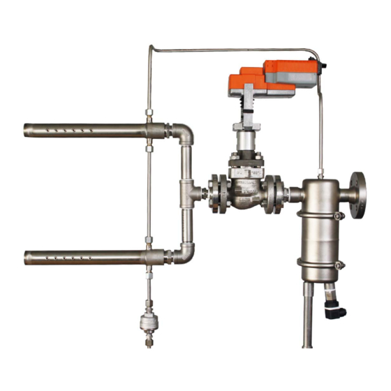
Now th e main portion of the steam flo ws throug h the control valve (7). The amount of steam is reg ulated over the operation switch (11). HygroMatik DDS Type A HygroMatik DDS Type C *all stainless steel contruction... -
Page 10: Strainer
5. Strainer There sho uld be a strainer inst alled in the steam supply line directly in front of every separator. Only if this is done can it be guaranteed that there are no fore ign particles in the hu midifier unit. -
Page 11: Separator
6. Separator The st ainless st eel sep arator is the essent ial comp onent for moisture sep aration. The sep arator is a vailable in version s 20 and 40. The separator size is depen dent upon the desired steam output and available steam pressure. -
Page 12: Control Valve And Actuator
As a general rule the customer is free to use any typical co ntrol valve which is approved for steam control. Standard are the Spirax-Sarco Valves from HygroMatik. Alterna- tive suppliers can be listed on application. Spirax-Sarco control valves Type LE33; KE63 Flanged Kvs-value [m³/h]... -
Page 13: Actuator
In order to comply with DIN 32 730* an electrical actuator must have a fail-safe function so that in the case of a power failure the Type Hygromatik E-4111680 control valve is reset into a safe position (fully closed). Pneumatic Actuator Pneumatic Actua tors are contro lled using compre ssed air (e.g. -
Page 14: Start-Up Safety Switch
8. Start-up safety switch The start-up safety switch ensures that no condensate from the steam network has ente red the air conditioning duct over the steaml lances. Electrical Start-up safety switch With an electrical actuator the supply volt age is looped through the st art-up safety switch. -
Page 15: Steam Lances
9. Steam Lances In t he steam lanc es (1) dry ste am is blown out of specially formed nozzles (2). They are designed for low n oise steam emission. The nozzles t ake steam from the driest area in the steam lance centre. -
Page 16: Technical Data
Technical Data Type 20 Type 40 Lance- Weight Weight code [mm] [mm] [kg] [mm] [mm] [kg] 0,88 1,54 1,14 1,97 1,40 2,39 1,80 3,03 1148 1268 2,26 1148 1275 3,78 1408 1528 2,65 1408 1535 4,40 1718 1838 3,11 1718 1845 5,15 2018... - Page 17 Steam lance piping for multiple steam lances . HygroMatik standard supply is for lengths of 300 mm und 450 mm. Distances are approx imate and ca n vary from installa- tion to inst allation. Piping shou ld be inst alled for even lance distribution along the duct height.
-
Page 18: Pressure Gauge Station
Installation of a pressu re gau ge on the steam in jection unit ensures immediate detection of pressure drops or fluctuations. The HygroMatik Pressure gau ge st ation consist s of an u p to 200°C temperat ure-tested, tubular sprin g pre ssure g auge (0- 6bar), a T-junction and a dual nipple. -
Page 19: Ball Float Steam Trap
11. Ball Float Steam Trap After separation from the steam inside the separator condensate is drained out through a ball float steam trap. 11.1 Function The discharge valve is controlled by the b all floa t depe ndent upon the density of the incoming medium. Starting Position / Air When the u nit starts, a ir pre sent in the system is discharged through the thermostatic air extractor fan. -
Page 20: Technical Data
11.2 Technical Data 11.2.1 KS-Condensate Drain for DDS Type A Screwfitting : 1/2“ external thread Materials: Clip Stainless steel 1.4404 Float Stainless Steel 1.4404 Flange seal Soft seal Adjust. screw Stainless Steel 1.4404 Housing Stainless Steel 1.4404 The KS-Condensate Drain for Type A is integrated into the sepa- rator. -
Page 21: Thermostatic Capsule Steam Trap
12. Thermostatic Capsule Steam Trap Condensate that has co llected in the stea m lance heating sys- tem is discharged through a thermostatic capsule steam trap. 12.1 Function The discha rge valve is controlled de pendent upon the ca psule volume and t he temperat ure an d pressur e of t he in coming medium. -
Page 22: Technical Data
12.2 Technical Data Type Spirax Sarco MST 21 max. operating pressure 18 bar max. operating temperature 210°C Dimensions: 45 mm Materials: Housing Stainless Steel 1.4305 Cover Stainless Steel1.4057 Capsule Stainless Steel 1.4541 Spring Stainless Steel 1.4300 Spacer Stainless Steel 1.4301 Strainer Stainless Steel 1.4301 Fill element... -
Page 23: Humidification Output
13. Humidification Output The maximum humidification output [kg/h] of one steam injection unit depends upon the available steam pressure in bar. Maximum humidif ication outp ut can be more than 770 kg/h (Type A) or 730 kg/h (Type C). Maximum operating pressure is pmax = 4 bar. - Page 24 Example: Desired humidification output: 110 kg/h Operating pressure, p = 2 bar The le ngth an d number of steam lances is d etermined b y the duct dimensions. See Section 9 "Steam Lances". Result: Follow the opera ting pre ssure line until the de sired humidif ica- tion output in kg/h is reached.
-
Page 25: Separator Type 20 With One Steam Lance
13.3 Separator Type 20 with one steam lance KVS-Value [m³/h] Pressure [bar] Page 25... -
Page 26: Separator Type 20 With Multiple Steam Lances
13.4 Separator Type 20 with multiple steam lances KVS-Value [m³/h] Pressure [bar] Page 26... -
Page 27: Separator Type 40 With One Steam Lance
13.5 Separator Type 40 with one steam lance KVS-Value[m³/h] Pressure [bar] Page 27... -
Page 28: Separator Type 40 With Multiple Steam Lances
13.6 Separator Type 40 with multiple steam lances KVS-Value [m³/h] Pressure [bar] Page 28... -
Page 29: Graph For Determing Absorption Distance
14. Graph for Determing Absorption Distance Page 29... -
Page 30: Installation
Matik steam injection humidifier in a safe and proper manner. Warning: this steam injection humidifier may only be installed by qualified personnel. HygroMatik c an accept no responsibility for any damage caused by incorrect installation. Please observe all sa fety and hazard instructions supplied with the steam injection humidifier. -
Page 31: Attaching Steam Pipes
Dimension the on-site steam connections (insulated) so that a steam velocity of 25 m/s is not exceeded. HygroMatik reco mmends the inst allation o f a shu t-off valve in front of the steam injection system in order to facilitate any necessary maintenance work. -
Page 32: Electrical Installation
Install a pressure sensor in the ducting and integrate this into the safety chain. The pressure se nsor prevents an ove r-humidifica- tion of the ducting in the case of a malfunctioning fan. HygroMatik Actuator wiring diagram Circuitry for alternative actuators are to be found in the relevant installations documents. -
Page 33: Separators
15.3 Separators Warning: Before installation, check out the steam supply piping. It must be established that the steam humidifier is su pplied with as dry a steam as possible (steam with as little condensate as possible). Steam pressure at the separator entry point must not exceed 4 bar. -
Page 34: Control Valve And Actuator
15.4 Control Valve and Actuator If the valve is o n site th en the necessary connections between valve and separator are fitted. All other parts are delivered sep- arately (e.g. connection bolts and flange seals). Only actuators which are suitable and certified for steam regula- tion may be used. -
Page 35: Pneumatic Start-Up Safety Feature
15.5 Pneumatic Start-up safety feature Note: Pneumatic st art-up safety is se t at 96°C. This value can be altered only by the manufacturer. First install a T-piece with a 1/2" exit in the condensate piping in front of the condensate drain. A T-piece with a 1/8"... -
Page 36: Steam Lances
HygroMatik can supp ly st ainless stee l st andard modules for lance pitches of 300 und 450 mm. - Page 37 In order to prevent steam condensing on the duct inner walls the lances should be inst alled according to the fo llowing dimen- sions: Dimension [mm] Type DDS 20 20-80 Type DDS 40 20-80 *„k“ is the necessary drill diameter in the duct wall A duct wall thickness of 30mm is assumed.
- Page 38 Number Description Duct Screw M6x35 Nut M10 Steam Lance Threaded bar M10 & M8 x 250 Angle anti-vibration collar * In installation set B-4600100. Lance guide is installed in the following manner: - feed bar through hole in angle . - Screw M10 bar end in the steam lance.
-
Page 39: Installation Examples
15.7 Installation Examples Note: If lan ces are positioned vertically th en the steam sup ply piping should have a n add itional float con trolled condensate drain. Page 39... - Page 40 Position lances in the duct centre if possible. If the humidifier blows into a comp act multi-zone unit then should be installed directly in the air flow and as close as possi- ble to the fan. The bif urcated pip e shou ld never be inst alled le ss th an one meter in fro nt o f th e fa n suct ion side.
-
Page 41: Steam Lance Heating System
15.8 Steam Lance Heating System Warning: the line to the heating system must be able to tolerate pressures of up to maximum 8 bar. Note: the pipe is easy to bend with a suitable tool. The customer must adjust the pipe in accor dance the conditions on site. Take care not to kink the pipe when bending. -
Page 42: Check List
15.9 Check List Warning: The steam injection humidif ier may only be operated by qualified and authorised personnel. Before switching on the steam injection humidifier please check for correct installation by going through the following check list: - Have the steam supply lines been flushed out? - Are th e steam supply and condensate lines properly connected and secure? - Has th e entire steam supply line up to the contro l valve been... -
Page 43: Initial Operation
16. Initial Operation Warning: the steam injection hu midifier may only be op erated by qualified personnel. Warning: for actuator initial operation please refer to the instruc- tions of the reg ulator and/or installations company. Initial opera- tion should only b e done by a traine d expert or service technician. - Page 44 Set the Max. Hygrost at to the desired va lue. Set the hu midity sensor to the desired value and activate the actuator. Note: Periodic filter cleaning is re commended in o rder to pre- vent the control valve from excessive wear. Before cleaning the filter always shut off the ste am supply and allow the system to cool down.
-
Page 45: Maintenance
17. Maintenance The HygroMatik steam injection hum idifier is ea sy to maintain. However, inadequate or improper maintenance can lead to oper- ational malfunct ions. Regular maintenan ce is essential so that your steam injection humidifier achieves a long, trouble free life span. -
Page 46: Ball Float Condensate Drain
» Check for leakages by re-start. Use only original HygroMatik parts. Maintenance set for DDS 20 Type A: B-4111917 Maintenance set for DDS 40 Type A: B-4111919 The maintenance sets include 1x sieve filter, flange seal, steam supply entry seal, and seals for the ball float and drain. -
Page 47: Thermostatic Capsule Steam Trap Type Mst21
» Screw down new complete float unit (E-C) with valve screws (D) . » Screw down cover with new seal (T). Use HygroMatik spare parts number E-4111834 Exchanging air vent » Loosen C spring clamp (L). » Remove capsule element (H) and spacer (M). -
Page 48: Malfunctions
18. Malfunctions Problem Possible Cause to do No steam is coming • Defective Hygrostat or humidity • Check Hygrostaten and/or sensor humitiy sensor and repair out of steam lance or replace as necessary. • Defective Control Valve • Check valve and clean it or replace as necessary. - Page 49 Possible Cause to do Problem Condensate is co- • Steam trap drain is considerably • Install condensate drain higher that the DDSystem. beneath the humidifier ming out of steam level and pump out the lance. resultant condensate to a suitable place. •...
-
Page 50: Dismantling
19. Dismantling After the steam injection humidifier is no longer in use it must be dismantled (scrapped and disposed of) following the in stallation procedures in reverse order. Warning: Dismantling the unit may only be done by trained and qualified personnel, the electrical dismantling by trained electro- personnel. -
Page 51: Steam Injection System Dimensions And Installation Schematic
20. Steam Injection System dimensions and Installation Schematic. * Steam injection system Type A (stainless steel) *Steam Injection system Type C (Mixed materials) Standard dimensions 300 and 500; other graduations possible on request *all dimensions in mm! Page 51... -
Page 52: Spare Parts
21. Spare Parts Version A Version C type type Article Number Description Separators E-4111090 Separator, without additions E-4111092 Separator, without additions B-4500001 Separator DDS20 incl. ball float steam trap and dirt trap B-4500003 Separator DDS40 incl. ball float steam trap and dirt trap B-4111917 maintenance set DDS20 Version A (encloses: seals, dirt trap) B-4111919... - Page 53 Version A Version C type type Article Number Description Steam lance E-4111000 steam lance 20, Code 1, 218 mm fitting lenght E4111002 steam lance 20, Code 1.5, 393 mm fitting lenght E-4111004 steam lance 20, Code 2, 568 mm fitting lenght E-4111006 steam lance 20, Code 3, 838 mm fitting lenght E-4111008...
-
Page 54: Fax Form - Order For Spare Parts
22. Fax Form - Order for spare parts Fax Form Please copy, fill out and fax to: Badgermeter Swiss AG 031 931 08 67 Fax.Nr. 3006 Bern Tel. 031 932 01 11 Spare Parts Fax Order Form for Unit -Type *______________ Serial Nr.* ___________________ From Department: ______________ Order Number: __________________ Number of pieces... - Page 56 12/2004...
Need help?
Do you have a question about the DDS 20 and is the answer not in the manual?
Questions and answers