Table of Contents
Advertisement
KOBALT® and the K & Design® are registered
trademarks of LF, LLC. All rights reserved.
ATTACH YOUR RECEIPT HERE
Serial Number
Questions, problems, missing parts? Before returning to your retailer, call
our customer service department at 1-888-3KOBALT (1-888-356-2258),
8:00 a.m. - 8:00 p.m., EST, Monday - Friday.
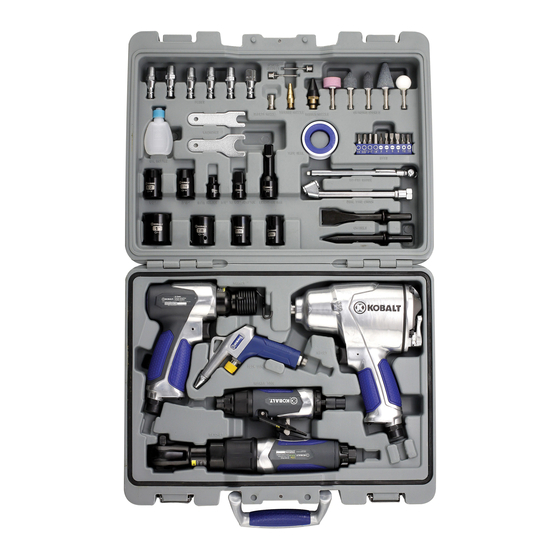
50-PIECE AIR TOOL KIT
SPORTS
NEEDLES
PLUGS
SAFETY
NOZZLE
WRENCHES
OIL BOTTLE
1/2"
7/16"
BITS HOLDER
3/8" TO 1/2"
EXTENSION BAR
ADAPTOR
1"
7/8"
11/16"
9/16"
HAMMER
BLOW GUN
ROTARY TOOL
RATCHET
TAPERED
RUBBER
GRINDING STONES
NOZZLE
NOZZLE
TAPE SEAL
BITS
50-PSI GAUGE
DUAL TIRE CHUCK
CHISELS
IMPACT
Purchase Date
1
ITEM #0002174
MODEL #SGY-AIR161
Français p. 32
Español p. 64
Advertisement
Table of Contents

Related Manuals for Kobalt SGY-AIR161


Summary of Contents for Kobalt SGY-AIR161
- Page 1 ITEM #0002174 50-PIECE AIR TOOL KIT KOBALT® and the K & Design® are registered MODEL #SGY-AIR161 trademarks of LF, LLC. All rights reserved. Français p. 32 Español p. 64 SPORTS NEEDLES PLUGS SAFETY TAPERED RUBBER GRINDING STONES NOZZLE NOZZLE NOZZLE...
-
Page 2: Table Of Contents
TABLE OF CONTENTS Safety Information ....................3 Package Contents ....................9 Preparation ......................12 Assembly Instructions ..................12 Operating Instructions ..................20 Care and Maintenance ..................26 Troubleshooting ....................27 Warranty ......................27 Parts List ......................28 IMPORTANT: To operate correctly, this tool requires airflow that is at least 6 cubic feet per minute (CFM), 4.5 CFM, 4 CFM, at 90 pounds per square inch (PSI). -
Page 3: Safety Information
SAFETY INFORMATION Please read and understand this entire manual before attempting to assemble, operate or install the product. WA R N I N G Improper operation or maintenance of this product could result in serious injury and property damage. Read and understand all warnings and operation instructions before using this equipment. - Page 4 WA R N I N G RISK OF EYE OR HEAD INJURY WHAT COULD HAPPEN HOW TO PREVENT IT Air powered equipment and power tools Always wear ANSI approved Z87.1 are capable of propelling materials such safety glasses with side shields. as fasteners, metal chips, sawdust and Never leave operating tool unattended.
- Page 5 WA R N I N G INHALATION HAZARD WHAT COULD HAPPEN HOW TO PREVENT IT Abrasive tools, such as grinders, Always wear properly fitting facemask sanders and cut-off tools generate dust or respirator when using such tools. and abrasive materials, which can be harmful to human lungs and respiratory system.
- Page 6 WA R N I N G RISK OF INJURY WHAT COULD HAPPEN HOW TO PREVENT IT Loss of control of the tool can lead to Never use tool while using drugs or injury to self or others. alcohol. Don't overreach. Keep proper footing and balance.
- Page 7 WA R N I N G RISK OF ELECTRIC SHOCK WHAT COULD HAPPEN HOW TO PREVENT IT Air tool accessories such as impact Thoroughly investigate the workpiece sockets, chisels and grinding stones for possible hidden wiring before that come into contact with hidden performing work.
- Page 8 PRODUCT SPECIFICATIONS 1/2 IN. AIR IMPACT WRENCH COMPONENT SPECIFICATIONS SQUARE DRIVE 1/2 IN. FREE SPEED 7,200 RPM +/- 10% MAXIMUM TORQUE 350 FT.-LBS. AVERAGE AIR CONSUMPTION 6 CF M AIR INLET 1/4 IN. NPT AIR HOSE 3/8 IN. WORKING PRESSURE 90 PSI 3/8 IN.
-
Page 9: Package Contents
PACKAGE CONTENTS PART DESCRIPTION QTY. 1/2 in. Impact Wrench SPORTS NEEDLES 3/8 in. Ratchet Wrench Air Hammer PLUGS SAFETY TAPERED RUBBER GRINDING STONES NOZZLE NOZZLE NOZZLE 1/4 in. Rotary Tool WRENCHES Blow Gun TAPE SEAL BITS OIL BOTTLE Spring Retainer 50-PSI GAUGE 3 in. - Page 10 PACKAGE CONTENTS 1/2 IN. AIR IMPACT WRENCH PART DESCRIPTION QUANTITY 1/2 in. Impact Wrench Anvil Trigger Switch Air Inlet 3/8 IN. AIR RATCHET WRENCH QUANTITY PART DESCRIPTION 3/8 in. Air Ratchet Wrench Anvil F/R Knob Trigger Air Regulator Exhaust Deflector Air Inlet Steel Ball Indicator...
- Page 11 PACKAGE CONTENTS AIR HAMMER PART DESCRIPTION QUANTITY Air Hammer Spring Retainer Chisel Trigger Cylinder Air Inlet 1/4 IN. AIR ROTARY TOOL PART DESCRIPTION QUANTITY 1/4 in. Air Rotary Tool Collet Jacket Collet Holder Collet Trigger Lever Air Regulator Exhaust Deflector Steel Ball Indicator Air Inlet...
-
Page 12: Preparation
PREPARATION Before beginning assembly of product, make sure all parts are present. Compare parts with package contents list above. If any part is missing or damaged, do not attempt to assemble the product. Estimated Assembly Time: 5-10 minutes Tools Required for Assembly (not included): Adjustable wrench ASSEMBLY INSTRUCTIONS 1/2 IN. - Page 13 ASSEMBLY INSTRUCTIONS 3. Place 2 - 3 drops of air tool oil into the male plug before each use. 4. Choose the correct impact socket as needed and mount it onto the anvil (B1). WA R N I N G Only use impact sockets that have an RPM rating equal to or greater than the tool itself.
- Page 14 ASSEMBLY INSTRUCTIONS 6. Connect air supply hose to the male plug. Set the working pressure at 90 PSI for best tool performance. NOTE Working pressure refers to the air line pressure set to tool when tool is under working conditions. 3/8 IN.
- Page 15 ASSEMBLY INSTRUCTIONS 3. Place 2 - 3 drops of air tool oil into the male plug before each use. 4. Mount the 3/8 in. to 1/2 in. adapter onto the anvil (B2) if necessary, and then choose the correct impact socket as needed and mount it onto the adapter.
- Page 16 ASSEMBLY INSTRUCTIONS AIR HAMMER 1. Remove the air inlet protective cap from the air inlet (F3). 2. Mount a male plug by hand into the air inlet (F3). NOTE Use thread sealant tape on the male plug and tighten it with a wrench (not included) for airtight connection.
- Page 17 ASSEMBLY INSTRUCTIONS 4. Insert a chisel (C3) into the opening of cylinder (E3). 5. Screw the spring retainer (B3) onto the cylinder (E3) and firmly secure it. 6. Connect air supply hose to the male plug. Set the working pressure at 90 PSI for best tool performance.
- Page 18 ASSEMBLY INSTRUCTIONS 1/4 IN. AIR ROTARY TOOL 1. Remove the air inlet protective cap from the air inlet (J4). 2. Mount a male plug by hand into the air inlet (J4). NOTE Use thread sealant tape on the male plug and tighten it with a wrench (not included) for airtight connection.
- Page 19 ASSEMBLY INSTRUCTIONS 4. Loosen the collet jacket (B4) counterclockwise by hand or with the large wrench while holding the small wrench on the flats of the collet holder (C4). 5. Insert a grinding accessory like a grinding stone into the collet (D4). 6.
-
Page 20: Operating Instructions
ASSEMBLY INSTRUCTIONS 7. Connect air supply hose to the male plug. Set the working pressure at 90 PSI for best tool performance. NOTE Working pressure refers to the air line pressure set to tool when tool is under working conditions. OPERATING INSTRUCTIONS 1/2 IN. - Page 21 OPERATING INSTRUCTIONS NOTE This tool features a power regulator valve. Turn the switch (D1) slowly forward until desired output is achieved. The Settings 1, 2, 3 do not denote a specific power output but are only for reference. "Setting 1" is the least amount of power, which is suitable for just mounting threaded fasteners on workpiece while "Setting 3"...
- Page 22 OPERATING INSTRUCTIONS NOTE This tool features a power regulator valve. Rotate the air regulator (E2) until desired output is achieved. The settings 1, 2, 3, 4 are only for reference and do not denote a specific power output. “Setting 1” (one-line symbol) is the least amount of power while “Setting 4”...
- Page 23 OPERATING INSTRUCTIONS 1/4 IN. AIR ROTARY TOOL Push lever (F4) forward and press down on the trigger (E4) to start the tool. NOTE This tool features a power regulator valve. Rotate the air regulator (G4) until desired output is achieved. The settings 1, 2, 3, 4 are only for reference and do not denote a specific power output.
- Page 24 OPERATING INSTRUCTIONS AIR BLOW GUN 1. Mount the female plug by hand into the air inlet. 2. The original nozzle can be removed from the blow gun when you are using the gun for another purpose. 3. Mount the rubber nozzle directly onto the gun for air dusting without scratching workpieces.
- Page 25 OPERATING INSTRUCTIONS 4. Mount the safety nozzle onto the blow gun. 5. Mount the tapered nozzle onto the safety nozzle for mattress inflating. 6. Mount the sports needle onto the safety nozzle for sports ball inflating.
-
Page 26: Care And Maintenance
OPERATING INSTRUCTIONS 7. Connect air supply hose to the blow gun. CARE AND MAINTENANCE An in-line oiler is recommended to be installed on air supply line as it increases tool life and keeps the tool in sustained operation. The in-line oiler should be regularly checked and filled with air-tool oil. -
Page 27: Troubleshooting
TROUBLESHOOTING PROBLEM POSSIBLE CAUSE CORRECTIVE ACTION 1. Grit or gum in tool. 1. Flush the tool with air-tool oil or gum solvent. 2. No oil in tool. 2. Lubricate the tool. 3. a. Adjust the regulator on the tool to 3. -
Page 28: Parts List
PARTS LIST For replacement parts, call our customer service department at 1-888-3KOBALT (1-888-356-2258), 8:00 a.m. - 8:00 p.m., EST, Monday - Friday. 1/2 IN. AIR IMPACT WRENCH 30 29 D 28 Description Qty. Description Qty. Part No. Part No. Housing Spring Bushing Trigger sleeve... - Page 29 PARTS LIST 3/8 IN. AIR RATCHET WRENCH Description Qty. Description Qty. Part No. Part No. Housing Front plate Valve stem Bearing Trigger Washer Trigger pin Thread ring gear Housing cover Idle gear Soft grip Gear pin Soft grip Gear plate Valve seat Clamp nut Throttle valve...
- Page 30 PARTS LIST AIR HAMMER Description Qty. Description Qty. Part No. Part No. Housing Trigger Housing cover Set pin Screw Plug End cover Oil seal Washer Rear plate Pin cover Valve Spring Set pin O-ring Front plate Air inlet Piston Muffler Cylinder Screw Spring retainer...
- Page 31 PARTS LIST 1/4 IN. AIR ROTARY TOOL Description Qty. Description Qty. Part No. Part No. Housing Air inlet Trigger Housing cover Lever Gasket Spring Bearing Rear plate Trigger pin Soft grip Rotor O-ring Rotor blade O-ring Cylinder Valve stem Rotor collar Valve spring Front plate O-ring...
Need help?
Do you have a question about the SGY-AIR161 and is the answer not in the manual?
Questions and answers