Sign In
Upload
Download
Add to my manuals
Delete from my manuals
Share
URL of this page:
HTML Link:
Bookmark this page
Add
Manual will be automatically added to "My Manuals"
Print this page
×
Bookmark added
×
Added to my manuals
Manuals
Brands
American Dish Service Manuals
Dishwasher
AF-3D
Service manual
American Dish Service AF-3D Series Service Manual
Hide thumbs
Also See for AF-3D Series
:
Owner's manual
(11 pages)
1
2
Table Of Contents
3
4
5
6
7
8
9
10
11
12
13
14
15
16
17
18
19
20
21
22
23
24
25
26
27
28
29
30
31
32
33
34
35
36
37
38
39
40
41
42
43
44
45
46
47
48
49
50
51
52
53
54
55
56
57
58
59
60
61
62
63
64
65
66
67
68
69
70
71
72
73
74
75
76
77
78
79
80
81
82
83
84
85
86
page
of
86
Go
/
86
Contents
Table of Contents
Troubleshooting
Bookmarks
Advertisement
Quick Links
1
Table of Contents
2
General
3
Operator Procedures
4
Chemicals
5
Preventive Maintenance
6
Troubleshooting
7
Repair Procedures
Download this manual
Effective Date: May, 2008
American Dish Service
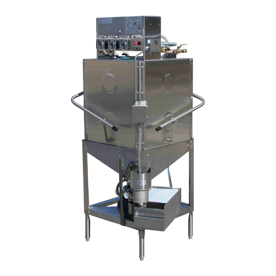
ADS UPRIGHT DISHWASHERS
MODELS: AF/AFC-3D, AF/AFC-3DS, LW/LWC, 5AG, AF/AFC/AFB, AD25
900 Blake Street
SERVICE MANUAL
Edwardsville, Kansas 66111
(913)-422-3700
© 05/08
Table of
Contents
Previous
Page
Next
Page
1
2
3
4
5
Advertisement
Need help?
Do you have a question about the AF-3D Series and is the answer not in the manual?
Ask a question
Questions and answers
Related Manuals for American Dish Service AF-3D Series
Dishwasher American Dish Service AF-3D Owner's Manual
Ads upright dishwashers (11 pages)
Commercial Food Equipment American Dish Service AF-3D-S Installation Instructions Manual
(20 pages)
Dishwasher American Dish Service ET Series Installation Instructions
Undercounter dishmachines (5 pages)
Dishwasher American Dish Service ADC-66 L-R/R-L Parts Manual
Ads conveyor dishwasher (46 pages)
Dishwasher American Dish Service ADC-44 Installation Instructions Manual
208/240v, 3-ph, 60a or 90a for 66 high temp or chemical sanitizer conveyor dishmachines (24 pages)
Dishwasher American Dish Service ASQ Installation And Operation Instructions Manual
(7 pages)
Dishwasher American Dish Service ASQ Service Manual
(68 pages)
Dishwasher American Dish Service ASQ Installation Instructions Manual
(16 pages)
Dishwasher American Dish Service ASQ II Installation Instructions Manual
(21 pages)
Dishwasher American Dish Service ET-AF Service Manual
(86 pages)
Dishwasher American Dish Service 5-AG-S Parts Manual
Ads low temperature dishwasher (33 pages)
Dishwasher American Dish Service 5-CD LF/RF Parts Manual
Ads low temperature dishwasher (26 pages)
Dishwasher American Dish Service HT-25 Service Manual
(38 pages)
Dishwasher American Dish Service ADS HUB-40-HIGH TEMP Manual
Undercounter dishwashers (79 pages)
Dishwasher American Dish Service HT-25 Installation Instructions Manual
High temp dishmachine w/built-on booster combo (15 pages)
Dishwasher American Dish Service HT-25 Installation Instructions Manual
(20 pages)
This manual is also suitable for:
Af-3d-s series
L series
A series
W series
Et series
5 series
...
Show all
Afb
5ag
Af-3d
Afc-3d
Af-3ds
Afc-3ds
Lw
Lwc
Af
Afc
Ad25
W
Afw
Wc
Afwc
A 5af
5a
Ac
A
Et-af
Save PDF
Print
Rename the bookmark
Delete bookmark?
Delete from my manuals?
Login
Sign In
OR
Sign in with Facebook
Sign in with Google
Upload manual
Upload from disk
Upload from URL


Need help?
Do you have a question about the AF-3D Series and is the answer not in the manual?
Questions and answers