Table of Contents
Advertisement
Quick Links
Advertisement
Table of Contents

Related Manuals for Supermicro SuperServer 8049U-E1CR4T


Summary of Contents for Supermicro SuperServer 8049U-E1CR4T
- Page 1 SuperServer ® 8049U-E1CR4T USER’S MANUAL Revision 1.0a...
- Page 2 State of California, USA. The State of California, County of Santa Clara shall be the exclusive venue for the resolution of any such disputes. Supermicro's total liability for all claims will not exceed the price paid for the hardware product.
- Page 3 If you have any questions, please contact our support team at: support@supermicro.com This manual may be periodically updated without notice. Please check the Supermicro website for possible updates to the manual revision level. Warnings Special attention should be given to the following symbols used in this manual.
-
Page 4: Table Of Contents
SuperServer 8049U-E1CR4T User's Manual Contents Chapter 1 Introduction 1.1 Overview ..........................8 1.2 Unpacking the System ......................8 1.3 System Features ........................9 1.4 Server Chassis Features ....................10 Control Panel ........................10 Front Features ........................11 Rear Features ........................12 1.5 Motherboard Layout ......................13 Quick Reference Table ......................14 System Block Diagram ......................15... - Page 5 Contents Chapter 3 Maintenance and Component Installation 3.1 Removing Power ........................30 3.2 Accessing the System ......................30 3.3 Motherboard Components ....................32 Processor and Heatsink Installation ..................32 The Processor Carrier Assembly ...................32 Overview of the Processor Heatsink Module ..............33 Creating the Processor Carrier Assembly ..............34 Assembling the Processor Heatsink Module ..............35 Preparing the CPU Socket for Installation..............36 Installing the Processor Heatsink Module ..............37...
- Page 6 SuperServer 8049U-E1CR4T User's Manual 4.4 Jumpers ..........................71 Explanation of Jumpers ....................71 4.5 LED Indicators ........................73 Chapter 5 Software 5.1 Microsoft Windows OS Installation ..................74 5.2 Driver Installation ........................76 5.3 SuperDoctor 5 ........................77 ® 5.4 IPMI ............................78 Chapter 6 BIOS 6.1 Introduction .........................79 Starting BIOS Setup Utility ....................79...
- Page 7 Super Micro Computer, Inc. 980 Rock Ave. San Jose, CA 95131 U.S.A. Tel: +1 (408) 503-8000 Fax: +1 (408) 503-8008 Email: marketing@supermicro.com (General Information) support@supermicro.com (Technical Support) Website: www.supermicro.com Europe Address: Super Micro Computer B.V. Het Sterrenbeeld 28, 5215 ML...
-
Page 8: Overview
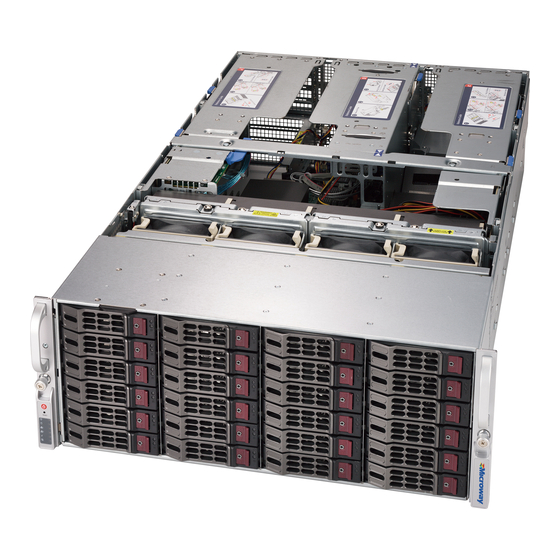
SuperServer 8049U-E1CR4T User's Manual Chapter 1 Introduction 1.1 Overview This chapter provides a brief outline of the functions and features of the SuperServer 8049U-E1CR4T.The system is based on the four-way Intel Xeon Scalable processor motherboard X11QPH+ and the 4U SC848UTS-R4800P chassis. It is useful for as in-memory database applications, ERP, CRM and business intelligence database applications, scientific research, scale-up HPC, and virtualization. -
Page 9: System Features
SC848UTS-R4800P Four Intel Xeon 82xx/62xx/52xx/42xx/32xx or 81xx/61xx/51xx/41xx/31xx processors (Intel Xeon Processor Scalable Family), supporting Intel UltraPath Interconnect (UPI) of up to 10.4 GT/s. For the latest CPU/memory updates, refer to the Supermicro website at. https://www.supermicro.com/products/motherboard/Xeon/C620/ X11QPH+.cfm. Note: For full PCI-E and memory capacity, all processors must be installed. -
Page 10: Server Chassis Features
SuperServer 8049U-E1CR4T User's Manual 1.4 Server Chassis Features Control Panel Power switches and status indicators are located on the control panel. Figure 1-1. Control Panel View Control Panel Features Item Feature Description The main power button is used to apply or remove power from the Power Button power supply to the server. -
Page 11: Front Features
Chapter 1: Introduction Information LED Status Description Continuously on and An overheat condition has occurred. (This might be caused by cable congestion.) Blinking red (1Hz) Fan failure; check for an inoperative fan. UID has been activated locally to locate the Solid blue server in a rack environment. -
Page 12: Rear Features
SuperServer 8049U-E1CR4T User's Manual Rear Features Figure 1-3. Chassis Rear View Rear Chassis Features Item Feature Description Power Supplies Four 1600 W power supply modules; or two modules (optional) Expansion Slots Fifteen slots for external cards (see Section 5.4 for details) Input/Output Ports Rear I/O ports (see below and Chapter 4 for details). -
Page 13: Motherboard Layout
Chapter 1: Introduction 1.5 Motherboard Layout Below is a layout of the X11QPH+ with jumper, connector and LED locations shown. See the following page for descriptions. For detailed descriptions, pinout information and jumper settings, refer to Chapter 4. JUIDB1 IPMI_LAN USB2/3(3.0) COM1 WIO x8... -
Page 14: Quick Reference Table
SuperServer 8049U-E1CR4T User's Manual Quick Reference Table Jumper Description Default Setting Power-Failure Throttling Enable Pins 1-2 (Normal) JBT1 CMOS Clear Open (Normal) JPG1 VGA Enable/Disable Pins 1-2 (Enabled) JPME1 Manufacturing Mode Select Pins 1-2 (Normal) JWD1 Watch Dog Enable Pins 1-2 (Reset) -
Page 15: System Block Diagram
Chapter 1: Introduction Description Status BMC_HB_LED1 BMC Heartbeat LED Blinking Green: BMC Normal LED1 UID LED Solid Blue: Unit Identified LED2 Onboard Power LED Solid Green: Power On Motherboard Block Diagram X40 ULTRA IO JLAN1 JLAN1 JVGA1 JCOM1 Dedicated X32 WIO X8 WIO in X16 Slot VGA CONN SSATA0, gen3... -
Page 16: Chapter 2 Server Installation
SuperServer 8049U-E1CR4T User's Manual Chapter 2 Server Installation 2.1 Overview This chapter provides advice and instructions for mounting your system in a server rack. If your system is not already fully integrated with processors, system memory etc., refer to Chapter 4 for details on installing those specific components. -
Page 17: Server Precautions
Chapter 2: Server Installation • Always verify that the rack is stable before extending a server or other component from the rack. • You should extend only one server or component at a time. Extending two or more simul- taneously might cause the rack to become unstable. Server Precautions •... -
Page 18: Circuit Overloading
SuperServer 8049U-E1CR4T User's Manual Circuit Overloading Circuit Overloading Consideration should be given to the connection of the equipment to the power supply circuitry Consideration should be given to the connection of the equipment to the power supply circuitry and the effect that any possible overloading of circuits might have on overcurrent protection and the effect that any possible overloading of circuits might have on overcurrent protection and power supply wiring. -
Page 19: Installing The Rails
Chapter 2: Server Installation 2.3 Installing the Rails This section provides information on installing the chassis into a rack unit with the rails provided. Due to the variety of rack units on the market, the assembly procedure might differ slightly. Also refer to the installation instructions that came with the rack unit you are using. Identifying the Rails The chassis package includes two rack rail assemblies in the rack mounting kit. -
Page 20: Installing The Inner Rails On The Chassis
SuperServer 8049U-E1CR4T User's Manual Installing the Inner Rails on the Chassis Installing the Inner Rails 1. Identify the left and right inner rails. They are labeled. 2. Place the inner rail firmly against the side of the chassis, aligning the hooks on the side of the chassis with the holes in the inner rail. -
Page 21: Installing The Outer Rails Onto The Rack
Chapter 2: Server Installation Installing the Outer Rails onto the Rack Installing the Outer Rails 1. Attach the short bracket to the outside of the long bracket. Align the pins with the slides and verify that both bracket ends face the same direction. 2. - Page 22 SuperServer 8049U-E1CR4T User's Manual Screws and Washers Screws and Washers Figure 2-4. Installing the Outer Rails to the Rack Note: Figures are for illustrative purposes only. Always install servers into racks from the bottom up.
-
Page 23: Installing The System Into A Rack
Chapter 2: Server Installation 2.4 Installing the System into a Rack Warning: Mounting the system into the rack requires at least two people to support the chassis during installation. Follow safety recommendations printed on the rails. Installing the Chassis into a Rack 1. -
Page 24: Removing The Chassis From The Rack
SuperServer 8049U-E1CR4T User's Manual Removing the Chassis from the Rack Warning: When servicing the server while in the rack, do not pull it more than half- way out. Full system servicing should be done on workbench, not on the rack. Re- moving the system from the rack requires at least two people to support the chassis. -
Page 25: Installing The Cable Management Arm
Chapter 2: Server Installation 2.5 Installing the Cable Management Arm The system supports a cable management arm (CMA) that keeps the rear cables organized and clear of the rail mechanisms when the system is extended out the front of the rack for maintenance. - Page 26 SuperServer 8049U-E1CR4T User's Manual Installing the Cable Management Arm 1. Slide CMA connector #1 forward onto the two posts on the rear of the right inner rail (right side when viewed from the front). It snaps into place. 2. Slide CMA connector #2 forward onto the two posts on the rear of the right middle rail. It snaps into place.
- Page 27 Chapter 2: Server Installation 3. Slide CMA connector #3 forward onto the two posts on the rear of the left middle rail. It snaps into place. 4. For CMA connector #4, align the metal tabs with the slots on the rear of the left outer rail and push it forward.
- Page 28 SuperServer 8049U-E1CR4T User's Manual Figure 2-10. Routing the Cables 5. Open the four red plastic caps and route the cables into the wire carrier. 6. If necessary, adjust the U-brackets to clear chassis components. Figure 2-11. Adjusting the U-Brackets...
- Page 29 Chapter 2: Server Installation 7. Use the six Velcro straps to secure the cables to the CMA. Use a strap on either side of each joint and one on each U-bracket, inserting it through the slot on the bracket. 8. Slide the chassis forward and backward in the rack to confirm that the cable management arm is operating smoothly.
-
Page 30: Chapter 3 Maintenance And Component Installation
SuperServer 8049U-E1CR4T User's Manual Chapter 3 Maintenance and Component Installation This chapter provides instructions on installing and replacing main system components. To prevent compatibility issues, only use components that match the specifications and part numbers given. Remove power from the system before installing or replacing components. Refer to Section 3.1. - Page 31 Chapter 3: Maintenance and Component Installation Release Tabs Figure 3-1. Removing the Chassis Covers...
-
Page 32: Motherboard Components
Thermal grease is pre-applied on a new heatsink. No additional thermal grease is needed. • Refer to the Supermicro website for updates on processor support. • All graphics in this manual are for illustration only. Your components may look different. -
Page 33: Overview Of The Processor Heatsink Module
Chapter 3: Maintenance and Component Installation Overview of the Processor Heatsink Module The Processor Heatsink Module (PHM) contains a heatsink, a processor carrier, and the processor. Heatsink with Thermal Grease Processor Carrier Processor Processor Heatsink Module Bottom View... -
Page 34: Creating The Processor Carrier Assembly
SuperServer 8049U-E1CR4T User's Manual Creating the Processor Carrier Assembly To install a processor into the processor carrier, follow the steps below: 1. Hold the processor with the LGA lands (gold contacts) facing up. Locate the small, gold triangle in the corner of the processor and the corresponding hollowed triangle on the processor carrier. -
Page 35: Assembling The Processor Heatsink Module
Chapter 3: Maintenance and Component Installation Assembling the Processor Heatsink Module After creating the processor carrier assembly, mount it onto the heatsink to create the processor heatsink module (PHM): 1. Note the label on top of the heatsink, which marks the heatsink mounting holes as 1, 2, 3, and 4. -
Page 36: Preparing The Cpu Socket For Installation
SuperServer 8049U-E1CR4T User's Manual Preparing the CPU Socket for Installation This motherboard comes with a plastic protective cover on the CPU socket. Remove it carefully to install the Processor Heatsink Module (PHM). CPU Socket with Plastic Protective Cover Remove the plastic protective cover from the CPU socket. -
Page 37: Installing The Processor Heatsink Module
Chapter 3: Maintenance and Component Installation Installing the Processor Heatsink Module After assembling the Processor Heatsink Module (PHM), install it onto the CPU socket: 1. Align hole 1 of the heatsink with the printed triangle on the CPU socket. See the left image below. -
Page 38: Memory Installation
*4Gb DRAM density is only supported on speeds up to 2666 MT/s **Only the 82xx and 62xx series support 2933 MT/s; for other processors, memory speed as supported by the Check the Supermicro website for possible updates to memory support. -
Page 39: Memory Population Guidelines
Then, if using two DIMMs per channel, install the second DIMM in the black slot. The following memory population sequence table was created based on guidelines provided by Intel to support Supermicro motherboards. The diagram is for illustrative purposes; your motherboard may look different. - Page 40 SuperServer 8049U-E1CR4T User's Manual Memory Population for X11 4-way Motherboard w/Half Memory Configuration Support (with 4 CPUs & 48 DIMMs Installed) 12 DIMMs per CPU Memory Population Sequence board CPU1: CPU1 + 12 DIMMs P1-DIMMC1/P1-DIMMC2/P1-DIMMB1/P1-DIMMB2/P1-DIMMA1/P1-DIMMA2/ P1-DIMMD2/P1-DIMMD1/P1-DIMME2/P1-DIMME1/P1-DIMMF2/P1-DIMMF1 CPU2: CPU2 + 12 DIMMs...
-
Page 41: Dcpmm Population Table Based On The 82Xx/62Xx/52Xx
Chapter 3: Maintenance and Component Installation DCPMM Population Table based on the 82xx/62xx/52xx Use the following tables to choose recommended slots with which to populate DCPMMs and DIMMs. Symmetric Population for 2-2-2 Channel Configuration (for each processor) Modes DIMMF1 DIMMF2 DIMME1 DIMME2 DIMMD1... - Page 42 SuperServer 8049U-E1CR4T User's Manual Validation Matrix (DDR4 DIMMs Validated with DCPMM) DIMM Capacity (GB) Ranks Per DIMM DIMM Type & Data Width DRAM Density (Stack) 1Rx4 16GB RDIMM 2Rx8 16GB 2Rx4 16GB 32GB LRDIMM 4Rx4 64GB LRDIMM 3DS 8Rx4 (4H)
-
Page 43: Installing Memory
Chapter 3: Maintenance and Component Installation Installing Memory ESD Precautions Electrostatic Discharge (ESD) can damage electronic com ponents including memory modules. To avoid damaging DIMM modules, it is important to handle them carefully. The following measures are generally sufficient. • Use a grounded wrist strap designed to prevent static discharge. - Page 44 SuperServer 8049U-E1CR4T User's Manual COM1 IPMI_LAN USB 2/3(3.0) JUSB3 JPCIE1 BMC_HB _LED1 CPLD BIOS JSTBY1 JBT1 I-SATA4~7 JUSB1 SXB2 JBAT1 S-SATA0~3 I-SATA0~3 PSU2 PSU1 CPU1 CPU2 IPMI CODE X11QPH+ BIOS REV.1.01 BAR CODE LICENSE CPU3 CPU4 FAN6 FAN5 Figure 3-3. Memory Slots...
-
Page 45: Motherboard Battery
Chapter 3: Maintenance and Component Installation Motherboard Battery The motherboard uses non-volatile memory to retain system information when system power is removed. This memory is powered by a lithium battery residing on the motherboard. Replacing the Battery Begin by removing power from the system as described in Section 3.1 and remove the cover as described in Section 3.2.. -
Page 46: Chassis Components
In addition the system features two 2.5 hot-swap SATA (SSD only) drives in the rear. For VROC configurations, refer to the VROC appendix in this manual. Note: Enterprise level drives are recommended for use in Supermicro servers. For information on recommended HDDs, visit the Supermicro website at http://www.supermicro.com/products/... -
Page 47: Drive Carriers
Chapter 3: Maintenance and Component Installation Drive Carriers The drives are mounted in drive carriers that simplify their removal from the chassis. These carriers also help promote proper airflow. Even carriers without drives must remain in the chassis for proper airflow. Each drive carrier has two LED indicators: an activity indicator and a status indicator. - Page 48 SuperServer 8049U-E1CR4T User's Manual Removing Drive Carrier 1. Press the release button on the drive carrier to extend the drive carrier handle. 2. Use the handle to pull the drive out of the chassis. Figure 3-6. Removing a Hard Drive Carrier...
- Page 49 Chapter 3: Maintenance and Component Installation Installing a Drive 1. Remove the screws securing the dummy drive into the drive carrier, and remove the dummy drive. 2. Install a drive into the carrier with the printed circuit board side facing down so that the mounting holes in the drive align with those in the carrier.
-
Page 50: Two Rear Auxiliary Storage Drives
SuperServer 8049U-E1CR4T User's Manual Two Rear Auxiliary Storage Drives Two 2.5" hot-swap SATA SSD drive bays are available on the chassis rear. These can be replaced using the same procedure as the front drives. SSD#1 SSD#0 Two SATA SSD Drives... -
Page 51: System Cooling
2. Push the release tab and pull the failed fan from the chassis. Fans can be replaced while the system is running. 3. Replace the failed fan with an identical fan, available from Supermicro. Push the new fan into the housing, making sure the air flow direction is the same. -
Page 52: Optional Exhaust Fans
SuperServer 8049U-E1CR4T User's Manual Optional Exhaust Fans The system supports up to three rear chassis fans. Choose up to three of the four fan positions shown below. Figure 3-10. Four Positions for Three Optional Rear Exhaust Fans Figure 3-11. Installing Optional Rear Exhaust Fans Installing Optional Exhaust Fans 1. -
Page 53: Air Shroud
Chapter 3: Maintenance and Component Installation Air Shroud Generally you do not need to remove the air shrouds to perform any service on the system. However, if you need to temporarily remove one (the air shroud should always be in place when the system is operating), follow this procedure. - Page 54 SuperServer 8049U-E1CR4T User's Manual Figure 3-13. Installing the PWS Air Shroud...
-
Page 55: Power Supply
The failed power module can be replaced without powering-down the system. Replace with the same model. Replacement modules can be ordered directly from Supermicro. An amber light on the power supply is illuminated when the power is switched off. An green light indicates that the power supply is operating. -
Page 56: Expansion Cards
SuperServer 8049U-E1CR4T User's Manual Expansion Cards The system supports PCI-E 3.0 expansion cards and up to six GPUs using pre-installed riser cards. Figure 3-15. Expansion Card Slots, Rear View Expansion Card Configurations Slot Mechanical Electrical Riser Card Full size x16 (CPU4) - Page 57 Chapter 3: Maintenance and Component Installation Installing Expansion Cards 1. Power down the system as described in Section 3.1 and remove the cover. 2. Remove the chassis bracket across the top of the chassis. Bracket Figure 3-16. Removing Bracket 3. Unlatch the required riser card housings. (Housings are pictured in drawings Figures 18–22.) On the rear of the chassis, each bracket is secured by a small black plastic flip- switch with an arrow on it.
- Page 58 SuperServer 8049U-E1CR4T User's Manual 4. Pull up the locking latches and pull up the expansion card housing. There are two latches on the left and right housing, one on the middle. Pull the bracket out of the chassis. • To access slots , pull the right-side housing.
- Page 59 Chapter 3: Maintenance and Component Installation Locking Latch Mounting Tab Mounting Tab (slide into rear (align on bracket post) chassis slot) Figure 3-19. Middle Expansion Card Housing...
- Page 60 SuperServer 8049U-E1CR4T User's Manual Locking Latches Figure 3-20. Left Expansion Card Housing...
- Page 61 Chapter 3: Maintenance and Component Installation Figure 3-21. Riser RSC-R2USW-4E8 and Expansion Cards...
- Page 62 SuperServer 8049U-E1CR4T User's Manual Figure 3-22. Installing the Internal Expansion Card 5. Insert the expansion card(s) into the riser card slot(s) while aligning the rear PCI shield. 6. Replace the riser card into the motherboard expansion slot while aligning the bracket into the chassis.
-
Page 63: Chapter 4 Motherboard Connections
Chapter 4: Motherboard Connections Chapter 4 Motherboard Connections This section describes the connections on the motherboard and provides pinout definitions. Note that depending on how the system is configured, not all connections are required. The LEDs on the motherboard are also described here. A motherboard layout indicating component locations may be found in Chapter 1. -
Page 64: Headers And Connectors
The JTPM1 header is used to connect a Trusted Platform Module (TPM)/Port 80, which is available from Supermicro. TPM/Port 80 is a security device which supports encryption and authentication in hard drives. It allows the motherboard to deny access if the TPM associated with the hard drive is not installed in the system. - Page 65 S-SATA4, S-SATA5) on the motherboard. The I-SATA ports are supported by the Intel C621 chipset, and the S-SATA ports are supported by Intel SCU. S-SATA4/S-SATA5 can be used with Supermicro SuperDOMs which are yellow SATA DOM connectors with power pins built in, and do not require external power cables. Supermicro SuperDOMs are backward-compatible with regular SATA HDDs or SATA DOMs that need external power cables.
-
Page 66: Front Control Panel
SuperServer 8049U-E1CR4T User's Manual Front Control Panel JF1 contains header pins for various control panel connections. Refer to the figure below for the pin locations and definitions of the control panel buttons and LED indicators. All JF1 wires have been bundled into a single cable to simplify this connection. Verify that the red wire plugs into pin 1 as marked on the motherboard. - Page 67 Chapter 4: Motherboard Connections Power Fail LED The Power Fail LED connection is located on pins 5 and 6 of JF1. Power Fail LED Pin Definitions (JF1) Pin# Definition 3.3V PWR Supply Fail Overheat (OH)/Fan Fail LED Connect an LED cable to pins 7 and 8 of the Front Control Panel to use the Overheat/Fan Fail LED connections.
- Page 68 SuperServer 8049U-E1CR4T User's Manual Power LED The Power LED connection is located on pins 15 and 16 of JF1. Power LED Pin Definitions (JF1) Pins Definition 3.3V PWR LED NMI Button The non-maskable interrupt (NMI) button header is located on pins 19 and 20 of JF1.
-
Page 69: Ports
Press the UID switch again to turn off the UID LED. The UID indicator provides easy identification of a system unit that might be in need of service. Note: UID can also be triggered via IPMI on the motherboard. For more information on IPMI, refer to the IPMI User's Guide posted on our website: http://www.supermicro.com. - Page 70 SuperServer 8049U-E1CR4T User's Manual Universal Serial Bus (USB) Ports There are two USB 3.0 ports (USB2/3) on the I/O back panel. A USB header that supports two USB 2.0 connections (USB0/1) is also located on the motherboard to provide front access support.
-
Page 71: Jumpers
Chapter 4: Motherboard Connections 4.4 Jumpers Explanation of Jumpers To modify the operation of the motherboard, jumpers are used to choose between optional settings. Jumpers create shorts between two pins to change the function associated with it. Pin 1 is identified with a square solder pad on the printed circuit board. See the motherboard layout page for jumper locations. - Page 72 SuperServer 8049U-E1CR4T User's Manual Power-Failure Throttling Enable/Disable The Power-Failure Throttling jumper is located at J17. Close pins 2-3 to enable the power throttling feature. The default setting is pins 1-2 for normal (disabled) operation. Power-Failure Throttling Jumper Settings Jumper Setting...
-
Page 73: Led Indicators
Chapter 4: Motherboard Connections 4.5 LED Indicators IPMI LAN LEDs An IPMI-dedicated LAN, supported by the onboard Baseboard Management controller, is located on the I/O back panel. The amber LED on the right indicates activity, while the green LED on the left indicates the speed of the connection. IPMI LAN Link LED (Left) &Activity LED (Right) Color State... -
Page 74: Chapter 5 Software
USB/SATA DVD drive, or a USB flash drive, or the IPMI KVM console. 2. Retrieve the proper RST/RSTe driver. Go to the Supermicro web page for your motherboard and click on "Download the Latest Drivers and Utilities", select the proper driver, and copy it to a USB flash drive. - Page 75 Chapter 5: Software 4. During Windows Setup, continue to the dialog where you select the drives on which to install Windows. If the disk you want to use is not listed, click on “Load driver” link at the bottom left corner. Figure 5-2.
-
Page 76: Driver Installation
The Supermicro website contains drivers and utilities for your system at https://www. supermicro.com/wftp/driver. Some of these must be installed, such as the chipset driver. After accessing the website, go into the CDR_Images (in the parent directory of the above link) and locate the ISO file for your motherboard. Download this file to a USB flash drive or a DVD. -
Page 77: Superdoctor ® 5
5.3 SuperDoctor ® The Supermicro SuperDoctor 5 is a program that functions in a command-line or web-based interface for Windows and Linux operating systems. The program monitors such system health information as CPU temperature, system voltages, system power consumption, fan speed, and provides alerts via email or Simple Network Management Protocol (SNMP). -
Page 78: Ipmi
SuperServer 8049U-E1CR4T User's Manual 5.4 IPMI The X11QPH+ supports the Intelligent Platform Management Interface (IPMI). IPMI is used to provide remote access, monitoring and management. There are several BIOS settings that are related to IPMI. For general documentation and information on IPMI, please visit our website at:... -
Page 79: Chapter 6 Bios
Chapter 6: BIOS Chapter 6 BIOS 6.1 Introduction This chapter describes the AMI BIOS setup utility for the X11QPH+ and provides the instructions on navigating the setup screens. The BIOS is stored in a Flash EEPROM and can be updated. Note: Due to periodic changes to the BIOS, some settings may have been added or deleted since this manual was published. - Page 80 SuperServer 8049U-E1CR4T User's Manual The Main tab page allows you to set the date and time, and it displays system information. System Date/System Time Use this option to change the system date and time. Highlight System Date or System Time using the arrow keys.
-
Page 81: Advanced Settings Menu
Chapter 6: BIOS 6.3 Advanced Settings Menu Use the arrow keys to select the Advanced submenu and press <Enter> to access the submenu items: Warning: Take Caution when changing the Advanced settings. An incorrect value, an incorrect DRAM frequency, or an incorrect BIOS timing setting may cause the system to malfunction. When this occurs, restore the setting to the manufacture default setting. - Page 82 SuperServer 8049U-E1CR4T User's Manual Bootup NumLock State Use this feature to set the Power-on state for the Numlock key. The options are Off and On. Wait For 'F1' If Error Select Enabled to force the system to wait until the 'F1' key is pressed if an error occurs. The options are Disabled and Enabled.
- Page 83 Chapter 6: BIOS CPU Configuration Warning: Setting the wrong values in the features below may cause the system to malfunction. Processor Configuration The following CPU information will be displayed: Processor BSP Revision Processor Socket Processor ID Processor Frequency Processor Max Ratio Processor Min Ratio Microcode Revision...
- Page 84 SuperServer 8049U-E1CR4T User's Manual PPIN Control Select Unlock/Enable to use the Protected-Processor Inventory Number (PPIN) in the system. The options are Unlock/Enable and Unlock/Disable. Hardware Prefetcher (Available when supported by the CPU) If this feature is set to Enable, the hardware prefetcher will prefetch streams of data and instructions from the main memory to the Level 2 (L2) cache to improve CPU performance.
- Page 85 Chapter 6: BIOS Advanced Power Management Configuration CPU P State Control SpeedStep (PStates) EIST (Enhanced Intel SpeedStep Technology) allows the system to automatically adjust processor voltage and core frequency in an effort to reduce power consumption and heat dissipation.
- Page 86 SuperServer 8049U-E1CR4T User's Manual Enhanced Halt State (C1E) Select Enable to enable "Enhanced Halt State" support, which will significantly reduce the CPU's power consumption by minimizing CPU's clock cycles and reduce voltage during a "Halt State." The options are Disable and Enable.
- Page 87 Chapter 6: BIOS Link L0p Enable Select Enable to enable Link L0p. The options are Disable, Enable, and Auto. Link L1 Enable Select Enable to enable Link L1 (Level 1 link). The options are Disable, Enable, and Auto. IO Directory Cache Select Enable for the IODC (I/O Directory Cache) to generate snoops instead of generating memory lockups for remote IIO (InvIToM) and/or WCiLF (Cores).
- Page 88 SuperServer 8049U-E1CR4T User's Manual Enable ADR Select Enable for ADR (Automatic Diagnostic Repository) support to enhance memory performance. The options are Enable and Disable. Memory Topology This item displays the information of onboard memory modules as detected by the BIOS.
- Page 89 Chapter 6: BIOS SDDC Plus One Select Enable for SDDC (Single Device Data Correction) Plus One support, which will increase the reliability and serviceability of your system memory. The options are Enable and Disable. ADDDC (Adaptive Double Device Data Correction) Sparing Select Enable for ADDDC sparing support to enhance memory performance.
- Page 90 SuperServer 8049U-E1CR4T User's Manual MCP1 (IIO PCIe Br5) This feature configures the PCI-E Bifuraction setting for a PCI-E port specified by the user. The options are x16 and Auto. Socket 0 PCI-E Br0D00F0 - Port 0/DMI (Available for CPU 1 Configuration ...
- Page 91 Chapter 6: BIOS PCI-E Completion Timeout Disable Select Enable to enable PCI-E Completion Timeout support. The options are Enable and Disable. PCI-E Completion Timeout Value This feature allows the user to set the PCI-E Completion Timeout value. The default setting is 260ms to 900ms.
- Page 92 SuperServer 8049U-E1CR4T User's Manual PCI-E Completion Timeout Value This feature allows the user to set the PCI-E Completion Timeout value. The default setting is 260ms to 900ms. Sck3 (Socket 3) RP (Root-Port) Correctable Err (Errors) Select Enable to enable interrupt on correctable errors occur on a root port. The default setting is Disable.
- Page 93 Chapter 6: BIOS Relaxed Ordering Select Enable to enable Relaxed Ordering support which will allow certain transactions to violate the strict-ordering rules of PCI and to be completed prior to other transactions that have already been enqueued. The options are Disable and Enable. Intel®...
- Page 94 SuperServer 8049U-E1CR4T User's Manual Onboard NVMe Mode Select Enable to enable onboard NVME mode support. The default setting is Disable. Intel® VMD Technology Intel® VMD for CPU2 Slot6 Intel® VMD for Volume Management Select Enable to enable Intel Volume Management Device Technology in the stack.
- Page 95 Chapter 6: BIOS South Bridge The following South Bridge information will display: • USB Module Version • USB Devices Legacy USB Support Select Enabled to support onboard legacy USB devices. Select Auto to disable legacy support if there are no legacy USB devices present. Select Disable to have all USB devices available for EFI applications only.
- Page 96 SuperServer 8049U-E1CR4T User's Manual (PCH) SATA Configuration When this submenu is selected, the AMI BIOS automatically detects the presence of the SATA devices that are supported by the Intel PCH chip and displays the following items: SATA Controller This item enables or disables the onboard SATA controller supported by the Intel PCH chip.
- Page 97 Chapter 6: BIOS SATA Device Type Use this item to specify if the device installed on the SATA port selected by the user should be connected to a Solid State drive or a Hard Disk Drive. The options are Hard Disk Drive and Solid State Drive.
- Page 98 SuperServer 8049U-E1CR4T User's Manual Spin Up Device On an edge detect from 0 to 1, set this item to allow the sSATA device installed on the sSATA port specified by the user to start a COMRESET initialization. The options are Enable and Disable.
- Page 99 Chapter 6: BIOS MMCFG Base This feature determines the lowest MMCFG (Memory-Mapped Configuration) base assigned to PCI devices. The options are 1G, 1.5G, 1.75G. 2G, 2.25G, and 3G. VGA Priority This feature selects the graphics device to be used as the primary video display for system boot.
- Page 100 SuperServer 8049U-E1CR4T User's Manual Super IO Configuration Super IO Chip AST2500 Serial Port 1 Configuration Serial Port Select Enabled to enable the onboard serial port specified by the user. The options are Enabled and Disabled. Device Settings This feature displays the base I/O port address and the Interrupt Request address of a serial port specified by the user.
- Page 101 Chapter 6: BIOS Serial Port 2 Attribute Select SOL to use COM Port 2 as a Serial_Over_LAN (SOL) port for console redirection. The options are COM and SOL. Serial Port Console Redirection COM 1 Console Redirection Select Enabled to enable COM Port 1 for Console Redirection, which will allow a client machine to be connected to a host machine at a remote site for networking.
- Page 102 SuperServer 8049U-E1CR4T User's Manual Flow Control Use this feature to set the flow control for Console Redirection to prevent data loss caused by buffer overflow. Send a "Stop" signal to stop sending data when the receiving buffer is full. Send a "Start" signal to start sending data when the receiving buffer is empty. The options are None and Hardware RTS/CTS.
- Page 103 Chapter 6: BIOS Console Redirection Settings (for SOL/COM2) Use this feature to specify how the host computer will exchange data with the client computer, which is the remote computer used by the user. Terminal Type Use this feature to select the target terminal emulation type for Console Redirection. Select VT100 to use the ASCII Character set.
- Page 104 SuperServer 8049U-E1CR4T User's Manual Recorder Mode Select Enabled to capture the data displayed on a terminal and send it as text messages to a remote server. The options are Disabled and Enabled. Resolution 100x31 Select Enabled for extended-terminal resolution support. The options are Disabled and Enabled.
- Page 105 Chapter 6: BIOS EMS Console Redirection Settings Out-of-Band Management Port The feature selects a serial port in a client server to be used by the Windows Emergency Management Services (EMS) to communicate with a remote host server. The options are COM1 (Console Redirection) and COM2/SOL (Console Redirection).
- Page 106 SuperServer 8049U-E1CR4T User's Manual High Precision Timer Select Enabled to activate the High Precision Event Timer (HPET) that produces periodic interrupts at a much higher frequency than a Real-time Clock (RTC) does in synchronizing multimedia streams, providing smooth playback and reducing the dependency on other timestamp calculation devices, such as an x86 RDTSC Instruction embedded in the CPU.
- Page 107 Configuration" in the "Chipset/North Bridge" submenu). Note 2: For more information on TPM, please refer to the TPM manual at http://www. supermicro.com/manuals/other. Intel® Virtual RAID on CPU When this submenu is selected and the RAID devices are detected, the BIOS screen displays the following items: Intel®...
-
Page 108: Event Logs
SuperServer 8049U-E1CR4T User's Manual 6.4 Event Logs Use this tab page to configure Event Log settings. Change SMBIOS Event Log Settings Enabling/Disabling Options SMBIOS Event Log Select Enabled to enable SMBIOS (System Management BIOS) Event Logging during system boot. The options are Enabled and Disabled. - Page 109 Chapter 6: BIOS SMBIOS Event Log Standard Settings Log System Boot Event Select Enabled to log system boot events. The options are Enabled and Disabled. MECI (Multiple Event Count Increment) Enter the increment value for the multiple event counter. Enter a number between 1 to 255. The default setting is 1.
-
Page 110: Ipmi
SuperServer 8049U-E1CR4T User's Manual 6.5 IPMI Use this tab page to configure Intelligent Platform Management Interface (IPMI) settings. • IPMI Firmware Revision: This feature indicates the IPMI firmware revision used in your system. • Status of BMC: This feature indicates the status of the BMC (Baseboard Management Controller) installed in your system. - Page 111 Chapter 6: BIOS keep all system event logs after each system reboot. The options are No, Yes, On next reset, and Yes, On every reset. When SEL is Full This feature allows the user to determine what the BIOS should do when the system event log is full.
- Page 112 SuperServer 8049U-E1CR4T User's Manual Update IPMI LAN Configuration Select Yes for the BIOS to implement all IP/MAC address changes at the next system boot. The default setting is Yes. IPMI LAN Selection Use this feature to configure the IPMI LAN mode setting. The options are Dedicated, Shared, and Failover.
-
Page 113: Security Settings
Chapter 6: BIOS 6.6 Security Settings Use this tab page to configure Security settings. Administrator Password Use this feature to set the administrator password which is required to enter the BIOS setup utility. The length of the password should be from 3 characters to 20 characters long. User Password Use this feature to set the user password which is required to enter the BIOS setup utility. - Page 114 SuperServer 8049U-E1CR4T User's Manual Secure Boot When you select this submenu and press the <Enter> key, the following items will display: • System Mode • Secure Boot • Vendor Keys Attempt Secure Boot If this feature is set to Enabled, the BIOS will attempt to use secure boot settings for system boot.
- Page 115 Chapter 6: BIOS Platform Key (PK) This feature allows the user to enter and configure a set of values to be used as a platform firmware key for the system. This set of values also indicate the size, the keys numbers, and the key source of the Platform Key.
-
Page 116: Boot Settings
SuperServer 8049U-E1CR4T User's Manual 6.7 Boot Settings Use this tab page to configure Boot Settings. Boot Mode Select Use this feature to select the type of devices to be used for system boot. The options are Legacy, UEFI (Unified Extensible Firmware Interface), and Dual. - Page 117 Chapter 6: BIOS Add New Boot Option This feature allows the user to add a new boot option to the boot priority features for your system. Add Boot Option Use this feature to specify the name for the new boot option. Path for Boot Option Use this feature to enter the path for the new boot option in the format fsx:\path\filename.efi.
- Page 118 SuperServer 8049U-E1CR4T User's Manual Delete Drive Option Select the target boot driver to delete from the boot priority list. Hard Disk Drive BBS Priorities • Boot Option #1 - #5 Network Drive BBS Priorities • Boot Option #1 ...
-
Page 119: Save & Exit
Chapter 6: BIOS 6.8 Save & Exit Use this tab page to configure Save & Exit settings. Save Options Discard Changes and Exit Select this option to quit the BIOS setup without making any permanent changes to the system configuration and reboot the computer. Select Discard Changes and Exit from the Exit menu and press <Enter>. - Page 120 SuperServer 8049U-E1CR4T User's Manual Default Options Restore Optimized Defaults To set this feature, select Restore Defaults from the Exit menu and press <Enter> to load manufacturer default settings which are intended for maximum system performance but not for maximum stability.
-
Page 121: Appendix A Bios Error Codes
When BIOS performs the Power On Self Test, it writes checkpoint codes to I/O port 0080h. If the computer cannot complete the boot process, a diagnostic card can be attached to the computer to read I/O port 0080h (Supermicro p/n AOC-LPC80-20). For information on AMI updates, please refer to http://www.ami.com/products/. -
Page 122: Appendix B Standardized Warning Statements For Ac Systems
Supermicro's Technical Support department for assistance. Only certified technicians should attempt to install or configure components. Read this appendix in its entirety before installing or configuring components in the Supermicro chassis. These warnings may also be found on our website at http://www.supermicro.com/about/... - Page 123 Appendix B: Standardized Warning Statements Warnung WICHTIGE SICHERHEITSHINWEISE Dieses Warnsymbol bedeutet Gefahr. Sie befinden sich in einer Situation, die zu Verletzungen führen kann. Machen Sie sich vor der Arbeit mit Geräten mit den Gefahren elektrischer Schaltungen und den üblichen Verfahren zur Vorbeugung vor Unfällen vertraut. Suchen Sie mit der am Ende jeder Warnung angegebenen Anweisungsnummer nach der jeweiligen Übersetzung in den übersetzten Sicherheitshinweisen, die zusammen mit diesem Gerät ausgeliefert wurden.
- Page 124 SuperServer 8049U-E1CR4T User's Manual . ٌ ا ك ً ف حالة و ٌ يك أى تتسبب ف اصابة جسذ ة ٌ هذا الزهز ع ٌ خطز !تحذ ز قبل أى تعول عىل أي هعذات،يك عىل علن بالوخاطز ال ا ٌجوة عي الذوائز...
- Page 125 Appendix B: Standardized Warning Statements Warnung Vor dem Anschließen des Systems an die Stromquelle die Installationsanweisungen lesen. ¡Advertencia! Lea las instrucciones de instalación antes de conectar el sistema a la red de alimentación. Attention Avant de brancher le système sur la source d'alimentation, consulter les directives d'installation. .יש...
- Page 126 SuperServer 8049U-E1CR4T User's Manual Warnung Dieses Produkt ist darauf angewiesen, dass im Gebäude ein Kurzschluss- bzw. Überstromschutz installiert ist. Stellen Sie sicher, dass der Nennwert der Schutzvorrichtung nicht mehr als: 250 V, 20 A beträgt. ¡Advertencia! Este equipo utiliza el sistema de protección contra cortocircuitos (o sobrecorrientes) del edificio.
- Page 127 Appendix B: Standardized Warning Statements Power Disconnection Warning Warning! The system must be disconnected from all sources of power and the power cord removed from the power supply module(s) before accessing the chassis interior to install or remove system components. 電源切断の警告...
- Page 128 SuperServer 8049U-E1CR4T User's Manual يجب فصم اننظاو من جميع مصادر انطاقت وإ ز انت سهك انكهرباء من وحدة امداد انطاقت قبم انىصىل إىن امنناطق انداخهيت نههيكم نتثبيج أو إ ز انت مكىناث الجهاز 경고! 시스템에 부품들을 장착하거나 제거하기 위해서는 섀시 내부에 접근하기 전에 반드시 전원...
- Page 129 Appendix B: Standardized Warning Statements Attention Il est vivement recommandé de confier l'installation, le remplacement et la maintenance de ces équipements à des personnels qualifiés et expérimentés. !אזהרה .צוות מוסמך בלבד רשאי להתקין, להחליף את הציוד או לתת שירות עבור הציוד واملدربيه...
- Page 130 SuperServer 8049U-E1CR4T User's Manual Warnung Diese Einheit ist zur Installation in Bereichen mit beschränktem Zutritt vorgesehen. Der Zutritt zu derartigen Bereichen ist nur mit einem Spezialwerkzeug, Schloss und Schlüssel oder einer sonstigen Sicherheitsvorkehrung möglich. ¡Advertencia! Esta unidad ha sido diseñada para instalación en áreas de acceso restringido. Sólo puede obtenerse acceso a una de estas áreas mediante la utilización de una herramienta especial,...
- Page 131 Appendix B: Standardized Warning Statements Battery Handling Warning! There is the danger of explosion if the battery is replaced incorrectly. Replace the battery only with the same or equivalent type recommended by the manufacturer. Dispose of used batteries according to the manufacturer's instructions 電池の取り扱い...
- Page 132 SuperServer 8049U-E1CR4T User's Manual هناك خطر من انفجار يف حالة اسحبذال البطارية بطريقة غري صحيحة فعليل اسحبذال البطارية فقط بنفس النىع أو ما يعادلها مام أوصث به الرشمة املصنعة جخلص من البطاريات املسحعملة وفقا لحعليامت الرشمة الصانعة 경고! 배터리가 올바르게 교체되지 않으면 폭발의 위험이 있습니다. 기존 배터리와 동일하거나 제...
- Page 133 Appendix B: Standardized Warning Statements ¡Advertencia! Puede que esta unidad tenga más de una conexión para fuentes de alimentación. Para cortar por completo el suministro de energía, deben desconectarse todas las conexiones. Attention Cette unité peut avoir plus d'une connexion d'alimentation. Pour supprimer toute tension et tout courant électrique de l'unité, toutes les connexions d'alimentation doivent être débranchées.
- Page 134 SuperServer 8049U-E1CR4T User's Manual Backplane Voltage Warning! Hazardous voltage or energy is present on the backplane when the system is operating. Use caution when servicing. バックプレーンの電圧 システムの稼働中は危険な電圧または電力が、 バックプレーン上にかかっています。 修理する際には注意く ださい。 警告 当系统正在进行时,背板上有很危险的电压或能量,进行维修时务必小心。 警告 當系統正在進行時,背板上有危險的電壓或能量,進行維修時務必小心。 Warnung Wenn das System in Betrieb ist, treten auf der Rückwandplatine gefährliche Spannungen oder Energien auf.
- Page 135 Appendix B: Standardized Warning Statements هناك خطز مه التيار الكهزبايئ أوالطاقة املىجىدة عىل اللىحة عندما يكىن النظام يعمل كه حذ ر ا عند خدمة هذا الجهاس 경고! 시스템이 동작 중일 때 후면판 (Backplane)에는 위험한 전압이나 에너지가 발생 합니다. 서비스 작업 시 주의하십시오. Waarschuwing Een gevaarlijke spanning of energie is aanwezig op de backplane wanneer het systeem in gebruik is.
- Page 136 SuperServer 8049U-E1CR4T User's Manual תיאום חוקי החשמל הארצי !אזהרה .התקנת הציוד חייבת להיות תואמת לחוקי החשמל המקומיים והארציים تركيب املعدات الكهربائية يجب أن ميتثل للقىاويه املحلية والىطىية املتعلقة بالكهرباء 경고! 현 지역 및 국가의 전기 규정에 따라 장비를 설치해야 합니다.
- Page 137 Appendix B: Standardized Warning Statements Attention La mise au rebut ou le recyclage de ce produit sont généralement soumis à des lois et/ou directives de respect de l'environnement. Renseignez-vous auprès de l'organisme compétent. סילוק המוצר !אזהרה .סילוק סופי של מוצר זה חייב להיות בהתאם להנחיות וחוקי המדינה التخلص...
- Page 138 SuperServer 8049U-E1CR4T User's Manual Warnung Gefährlich Bewegende Teile. Von den bewegenden Lüfterblätter fern halten. Die Lüfter drehen sich u. U. noch, wenn die Lüfterbaugruppe aus dem Chassis genommen wird. Halten Sie Finger, Schraubendreher und andere Gegenstände von den Öffnungen des Lüftergehäuses entfernt.
- Page 139 Verbindungskabeln, Stromkabeln und/oder Adapater, die Ihre örtlichen Sicherheitsstandards einhalten. Der Gebrauch von anderen Kabeln und Adapter können Fehlfunktionen oder Feuer verursachen. Die Richtlinien untersagen das Nutzen von UL oder CAS zertifizierten Kabeln (mit UL/CSA gekennzeichnet), an Geräten oder Produkten die nicht mit Supermicro gekennzeichnet sind.
- Page 140 .قيرح وأ لطع يف ببستي دق ىرخأ تالوحمو تالباك يأ مادختسا .ميلسلا سباقلاو لصوملا مجح لبق نم ةدمتعملا تالباكلا مادختسا تادعملاو ةيئابرهكلا ةزهجألل ةمالسلا نوناق رظحيUL وأCSA ( ةمالع لمحت يتلاوUL/CSA) لبق نم ةددحملاو ةينعملا تاجتنملا ريغ ىرخأ تادعم يأ عمSupermicro.
- Page 141 사항을 준수하여 제공되거나 지정된 연결 혹은 구매 케이블, 전원 케이블 및 AC 어댑터를 사용하십시오. 다른 케이블이나 어댑터를 사용하면 오작동이나 화재가 발생할 수 있습니다. 전기 용품 안전법은 UL 또는 CSA 인증 케이블 (코드에 UL / CSA가 표시된 케이블)을 Supermicro 가 지정한 제품 이외의 전기 장치에 사용하는 것을 금지합니다. Stroomkabel en AC-Adapter...
-
Page 142: Appendix C System Specifications
Appendix C System Specifications Processors Four Intel Xeon 82xx/62xx/52xx or 81xx/61xx/51xx processors in a Socket P0-LGA3647 Note: Refer to the motherboard specifications pages on the Supermicro website for updates to supported processors. Chipset Intel PCH C621 BIOS 128 Mb AMI Flash ROM Memory Supports up to 12 TB of DDR4 Registered ECC 3DS LRDIMM, LRDIMM, RDIMM, in 48 DIMM slots;... - Page 143 Appendix C: System Specifications Regulatory Compliance Electromagnetic Emissions: FCC Class A, EN 55032 Class A, EN 61000-3-2/3-3, CISPR 32 Class A Electromagnetic Immunity: EN 55024/CISPR 24, (EN 61000-4-2, EN 61000-4-3, EN 61000-4-4, EN 61000-4-5, EN 61000-4-6, EN 61000-4-8, EN 61000-4-11) Other: VCCI-CISPR 32 and AS/NZS CISPR 32 Environmental: Directive 2011/65/EU and Delegated Directive (EU) 2015/863 and Directive 2012/19/EU Safety: CSA/EN/IEC/UL 60950-1 Compliant, UL or CSA Listed (USA and Canada), CE Marking (Europe)
-
Page 144: Appendix D Uefi Bios Recovery
Warning: Do not upgrade the BIOS unless your system has a BIOS-related issue. Flashing the wrong BIOS can cause irreparable damage to the system. In no event shall Supermicro be liable for direct, indirect, special, incidental, or consequential damages arising from a BIOS update. - Page 145 USB device or a writable CD/DVD. Note 1: If you cannot locate the "Super.ROM" file in your drive disk, visit our website at www.supermicro.com to download the BIOS package. Extract the BIOS binary image into a USB flash device and rename it "Super.ROM" for the BIOS recovery use.
- Page 146 SuperServer 8049U-E1CR4T User Manual 3. After locating the healthy BIOS binary image, the system will enter the BIOS Recovery menu as shown below. Note: At this point, you may decide if you want to start the BIOS recovery. If you decide to proceed with BIOS recovery, follow the procedures below.
- Page 147 Appendix D: UEFI BIOS Recovery 5. After the BIOS recovery process is complete, press any key to reboot the system. 6. Using a different system, extract the BIOS package into a USB flash drive. 7. Press <Del> continuously during system boot to enter the BIOS Setup utility. From the top of the tool bar, select Boot to enter the submenu.
- Page 148 SuperServer 8049U-E1CR4T User Manual 8. When the UEFI Shell prompt appears, type fs# to change the device directory path. Go to the directory that contains the BIOS package you extracted earlier from Step 6. Enter flash.nsh BIOSname.### at the prompt to start the BIOS update process.
-
Page 149: Appendix E Ipmi Crash Dump
In the event of a processor internal error (IERR) that crashes your system, you may want to provide information to support staff. You can download a crash dump of status information using IPMI. The IPMI manual is available at https://www.supermicro.com/solutions/IPMI.cfm. Check IPMI Error Log 1. - Page 150 SuperServer 8049U-E1CR4T User's Manual Downloading the Crash Dump File 1. In the IPMI interface, click the Miscellaneous tab, then the Trouble Shooting option. 2. Click the Dump button and wait five minutes for the file to be created. (No confirm ation message will appear.)
-
Page 151: Appendix F Cpu-Based Raid For Nvme
Appendix F: CPU-Based RAID for NVMe Appendix F CPU-Based RAID for NVMe Intel Virtual RAID on CPU (Intel VROC) is an enterprise RAID solution for NVMe SSDs ® directly attached to Intel Xeon Scalable processors. Intel Volume Management Device (VMD) is an integrated controller inside the CPU PCI-E root complex. - Page 152 SuperServer 8049U-E1CR4T User's Manual Additional Information Additional information is available on the product page for the Supermicro add-on card and the linked manuals. www.supermicro.com/products/accessories/addon/AOC-VROCxxxMOD.cfm F.1 Hardware Key The Intel VROC hardware key is a license key that detects the Intel VROC SKU and activates the function accordingly.
- Page 153 Appendix F: CPU-Based RAID for NVMe F.2 Enabling NVMe RAID RAID for NVMe SSDs must be enabled through the UEFI BIOS. 1. Install the patch as described in the Restrictions and Requirements section on a previous page. 2. Reboot the server. 3.
- Page 154 SuperServer 8049U-E1CR4T User's Manual 6. Press [F4] to save the configuration and reboot the system. 7. Press [DEL] to enter BIOS. 8. Switch to Advanced > Intel(R) Virtual RAID on CPU > All Intel VMD Controllers > Create RAID Volume.
- Page 155 Appendix F: CPU-Based RAID for NVMe F.3 Status Indications An LED indicator on the drive carrier shows the RAID status of the drive. Drive Carrier Status LED Indicator Status State (red) Normal function Locating 4 Hz blink Fault Solid on Rebuilding 1 Hz Blink IBPI SFF 8489 Defined Status LED States...
-
Page 156: Appendix G Bsmi Chinese Safety Warnings
SuperServer 8049U-E1CR4T User's Manual Appendix G BSMI Chinese Safety Warnings Appendix G Traditional Chinese Version of Safety Warnings 安全警告 (注意這些警告標誌) 以下的警告標誌對於安全使用本設備非常重要,可以避免操作人員遭遇危險,以及財產 受到任何損 失。 錯誤使用本機器或忽視這本手冊,所引起的傷害或損失等級分類如下: WARNING (警 警 告 告 ) 此注意標誌提醒未能依照正確指示使用機器,可能導致生命危險 或造成嚴重傷 害。 CAUTION (注 注 意 意 ) 此注意標誌提醒未能依照正確指示使用機器,可能導致受傷或財產損失。... - Page 157 Appendix G: BSMI Chinese Safety Warnings WARNINGS (警告) 本機器必須用接地線與地面確實連接。 否則受到電擊或閃電時,將對您造成危 險。 如果電源插座沒有接地端子,或是有無法接地情況,請務必洽詢 專業技 術人員,妥善安裝這些設施。 電源必須在 100V 至 240V 正負 10%之間 使用額定合格開關來提供電源迴路。 機器安裝愈接近電源插座愈好。 移動機器必須由維護工程師來處理。 勿使用多孔插座或延長線,否則可能造成溫度過高而引起火災。 勿在電源線放置重物,否則可能引起火災或受到電擊。 勿踏在電源線上,及勿損傷或任意處理電源線,否則可能引起火災或 受到電 擊。 勿綁住或紮緊電源線,否則可能引起火災或受到電擊。 勿將花瓶、花盆或盛水容器放在機器上,如果水滴濺出,可能引起火 災或受 到電擊。 機器如果產生怪味或不正常聲響,必需立即關閉機器電源開關,然後 從插 座取下插頭。 絕對不可以沾濕的手插拔插頭,否則可能受到電擊。 插頭必須確實插妥在插座上,如果未能妥善插好,可能會引起火災。 僅可使用機器所附電源插頭。...
- Page 158 SuperServer 8049U-E1CR4T User's Manual 拔取電源線時,確實抓住插頭部位,否則導致插頭破裂可能引起火 災或受到 電擊。 不可企圖拆解或擅自修改機器,否則可能引起火災或受到電擊。 不可將機器安裝在下列場所: 濕氣高及多灰塵的地方。 地板不穩的地方。如果機器傾倒,可能造成傷害。 關閉上機蓋時,千萬不可將手放在上機蓋與主機體之間。 移動機器前,必須記住拔下插頭,否則插頭可能受損而引起火災 或受到 電擊。 為安全起見,夜晚無人使用伺服器時,必須確實將它的電源關閉。 連續假日長期無人使用伺服器時,必須確實將它的電源關閉。 插座周圍必須淨空,以便隨時可以很輕易的拔下插頭。 警告使用者: 這是甲類的資訊產品,在居住的環境中使用時,可能會造成 射頻干擾,在這種情況下,使用者會被要求採取某些適當的對策...
- Page 159 Appendix G: BSMI Chinese Safety Warnings 限 限 用 用 物 物 質 質 含 含 有 有 情 情 況 況 標 標 示 示 聲 聲 明 明 書 書 Declaration of the Presence Condition of the Restricted Substances Marking 設備名稱:伺服器/ Server Equipment name 型號(型式):848U-16...
- Page 160 SuperServer 8049U-E1CR4T User's Manual * 輸入額定: 100-127V ~, 60-50Hz, 12.0A 200-240V ~, 60-50Hz, 9.6A * 使用者不能任意拆除或替換內部配備...
Need help?
Do you have a question about the SuperServer 8049U-E1CR4T and is the answer not in the manual?
Questions and answers