Table of Contents
Advertisement
Quick Links
Advertisement
Table of Contents

Subscribe to Our Youtube Channel
Related Manuals for Supermicro SUPERSERVER 8048B-TR4F


Summary of Contents for Supermicro SUPERSERVER 8048B-TR4F
- Page 1 SUPERSERVER ® 8048B-TR4F 8048B-C0R4FT USER’S MANUAL Revision 1.0a...
- Page 2 This product, including software and documentation, is the property of Supermicro and/or its licensors, and is supplied only under a license. Any use or reproduction of this product is not allowed, except as expressly permitted by the terms of said license.
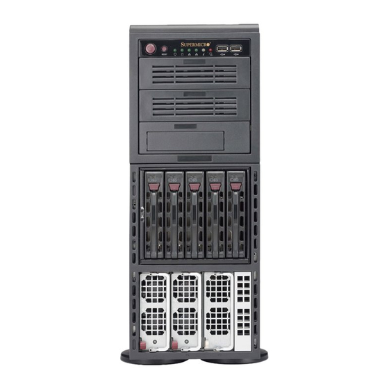
- Page 3 8048B-TR4F/C0R4FT Installation and maintenance should be performed by experienced technicians only. The SuperServer 8048B-TR4F/C0R4FT is a high-end server based on the 748TQ-R1K43B tower/4U rackmount chassis and the X10QBL-4(CT) quad processor serverboard. The only difference between the two server models is that the 8048B-C0R4FT server contains both SATA and SAS connections and 10G LAN Ports, while the 8048B-TR4F server only has SATA connections and 1G LAN Ports..
- Page 4 SUPERSERVER 8048B-TR4F/C0R4FT User's Manual Chapter 6: Advanced Chassis Setup Refer to Chapter 6 for detailed information on the 748TQ-R1K43B server tower/4U rackmount chassis. You should follow the procedures given in this chapter when installing, removing or reconfi guring SAS/SATA or peripheral drives and when replacing system power supply units and cooling fans.
- Page 5 Preface Notes...
-
Page 6: Table Of Contents
SUPERSERVER 8048B-TR4F/C0R4FT User's Manual Table of Contents Chapter 1 Introduction Overview ......................1-1 Serverboard Features ..................1-2 Processors ...................... 1-2 Memory ......................1-2 Serial ATA ....................... 1-2 SAS (8048B-C0R4FT Server Only) ..............1-3 Onboard Controllers/Ports ................1-3 Graphics Controller ..................1-3 Other Features .................... - Page 7 Table of Contents Circuit Overloading ..................2-3 Reliable Ground ..................2-4 Installing the System into a Rack ..............2-4 Removing the Feet ..................2-4 Identifying the Sections of the Rack Rails ............2-6 Tower Confi guration Instructions ..............2-11 Checking the Serverboard Setup ..............2-12 Checking the Drive Bay Setup ..............
- Page 8 Confi guring the Storage Module ..............6-3 Tower or Rack Confi guration................6-3 Adding Drives to the Storage Module ............. 6-5 Adding Five Hard Drives to a Supermicro Mobile Rack: ........ 6-8 Installing Hard Drives ..................6-10 Add-on Card/Expansion Slot Setup .............. 6-12...
- Page 9 Table of Contents Installing the Air Shroud ................6-14 System Fans ....................6-15 Replacing a Front Chassis Fan ..............6-15 Replacing a Rear Chassis Fan ..............6-16 Power Supply ....................6-17 Power Supply Failure ..................6-17 Chapter 7 BIOS Introduction ...................... 7-1 Starting the Setup Utility .................
- Page 10 SUPERSERVER 8048B-TR4F/C0R4FT User's Manual Notes...
-
Page 11: Chapter 1 Introduction
Chapter 1 Introduction Overview The SuperServer 8048B-TR4F/C0R4FT is a high-end server comprised of two main subsystems: the 748TQ-R1K43B tower/4U rackmount chassis and the X10QBL-4(CT) dual processor serverboard. Please refer to our web site for information on operating systems that have been certifi ed for use with the system (www.supermicro.com). -
Page 12: Serverboard Features
Serverboard Features At the heart of the SuperServer 8048B-TR4F/C0R4FT lies the X10QBL-4(CT), a quad processor serverboard based on the Intel PCH C602J chipset. Below are the main features of the X10QBL-4(CT). (See Figure 1-1 for a block diagram of the chipset). -
Page 13: Sas (8048B-C0R4Ft Server Only)
IPMI LAN port. Note 1: For more information on IPMI confi guration, please refer to the IPMI User's Guide posted on our website at http://www.supermicro.com/support/manuals/ Graphics Controller The X10QBL-4(CT) features an integrated ASpeed AST2400 BMC (Baseboard Controller) for a graphics controller. -
Page 14: Server Chassis Features
SUPERSERVER 8048B-TR4F/C0R4FT User's Manual Server Chassis Features The SuperServer 8048B-TR4F/C0R4FT is built upon the 748TQ-R1K43B tower/4U rackmount chassis. Details on the chassis and on servicing procedures can be found in Chapter 6. The following is a general outline of the main features of the chassis. -
Page 15: Front Control Panel
Chapter 1: Introduction Front Control Panel The control panel on the SuperServer 8048B-TR4F/C0R4FT provides you with system monitoring and control. LEDs indicate system power, HDD activity, network activity, system overheat and power supply failure. A main power button and a system reset button are also included. -
Page 16: Advanced Power Management
SUPERSERVER 8048B-TR4F/C0R4FT User's Manual Advanced Power Management Intel® Intelligent Power Node Manager (NM) The Intel Intelligent Power Node Manager (IPNM) provides your system with ® real-time thermal control and power management for maximum energy effi ciency. Although IPNM Specifi cation Version 1.5 is supported by the BMC (Baseboard Management Controller), your system must also have IPNM-compatible Manageability Engine (ME) fi... - Page 17 Chapter 1: Introduction Figure 1-1. Intel PCH C602J Chipset: System Block Diagram Note: This is a general block diagram. Please see Chapter 5 for details. Memory PCIE PCIE Memory Buffer Buffer VMSE0 VMSE0 CTRL CTRL CPU2 CPU3 QPI0 QPI0 Memory Memory Buffer Buffer...
-
Page 18: Contacting Supermicro
SUPERSERVER 8048B-TR4F/C0R4FT User's Manual Contacting Supermicro Headquarters Address: Super Micro Computer, Inc. 980 Rock Ave. San Jose, CA 95131 U.S.A. Tel: +1 (408) 503-8000 Fax: +1 (408) 503-8008 Email: marketing@supermicro.com (General Information) support@supermicro.com (Technical Support) Website: www.supermicro.com Europe Address: Super Micro Computer B.V. -
Page 19: Chapter 2 Server Installation
Rack and Server Precautions in the next section. Preparing for Setup The box the SuperServer 8048B-TR4F/C0R4FT was shipped in should include two sets of rail assemblies, two rail mounting brackets and the mounting screws you will need to install the system into the rack. Follow the steps in the order given to complete the installation process in a minimum amount of time. -
Page 20: Warnings And Cautions
SUPERSERVER 8048B-TR4F/C0R4FT User's Manual • This product is for installation only in a Restricted Access Location (dedicated equipment rooms, service closets and the like). • This product is not suitable for use with visual display work place devices according to §2 of the German Ordinance for Work with Visual Display Units. -
Page 21: Rack Mounting Considerations
Chapter 2: Server Installation Rack Mounting Considerations Warning! To prevent bodily injury when mounting or servicing this unit in a rack, you must take special precautions to ensure that the system remains stable. The following guidelines are provided to ensure your safety: •... -
Page 22: Reliable Ground
SUPERSERVER 8048B-TR4F/C0R4FT User's Manual Reliable Ground A reliable ground must be maintained at all times. To ensure this, the rack itself should be grounded. Particular attention should be given to power supply connections other than the direct connections to the branch circuit (i.e. the use of power strips, etc.). - Page 23 Chapter 2: Server Installation Removing the Chassis Feet 1. Place the chassis on its side with the chassis side cover facing upward. 2. Remove the screw holding the chassis foot in place. 3. The foot lock is a tab located in the center of the foot that prevents the foot from sliding.
-
Page 24: Identifying The Sections Of The Rack Rails
SUPERSERVER 8048B-TR4F/C0R4FT User's Manual Identifying the Sections of the Rack Rails The chassis package includes two rack rail assemblies in the rack mounting kit. Each assembly consists of two sections: an inner fi xed chassis rail that secures directly to the server chassis and an outer fi xed rack rail that secures directly to the rack itself (see Figure 2-2 for details). - Page 25 Chapter 2: Server Installation 5. Align the inner rails against the chassis, as shown in Figure 2-4. Confi rm that the rails are fl ushed against the edge of the chassis. Figure 2-4: Installing the Inner Rack Rails 6. Tighten the screws. Do not over tighten. 7.
- Page 26 SUPERSERVER 8048B-TR4F/C0R4FT User's Manual Installing the Outer Rails to the Rack (Figure 2-5) 1. Attach the front and rear short brackets to the outside of the long bracket. Both bracket ends must face the same direction. 2. Adjust both the brackets to the proper distance so that the rail fi ts snugly into the rack.
- Page 27 Chapter 2: Server Installation Installing the Chassis into a Rack 1. Confi rm that chassis includes the inner rails and the outer rails. 2. Line chassis rails with the front of the rack rails (Figure 2-6). Figure 2-6. Installing the Rack Rails...
- Page 28 SUPERSERVER 8048B-TR4F/C0R4FT User's Manual 3. Slide the chassis rails into the rack rails, keeping the pressure even on both sides (you may have to depress the locking tabs when inserting). When the server has been pushed completely into the rack, you should hear the locking tabs "click"...
-
Page 29: Tower Confi Guration Instructions
Chapter 2: Server Installation Tower Confi guration Instructions The SC748 tower/4U rackmount chassis is shipped with the chassis cover and feet pre-installed. To use the chassis as a desktop server, no other installation is required. Use the instructions in this section if you have converted the chassis for rack use and need to return the chassis to tower mounting. -
Page 30: Checking The Serverboard Setup
SUPERSERVER 8048B-TR4F/C0R4FT User's Manual approximately one-half inch over the front of the chassis (Figure 2-8). 3. Slide the chassis cover toward the rear of the chassis to lock the cover into place. Placing the Chassis Feet (Figure 2-9) 1. Place the chassis foot in the foot receptacle and slide the foot toward the front of the chassis. - Page 31 Chapter 2: Server Installation Figure 2-10: Removing the Chassis Cover Remove Screws Checking the Components and Setup 1. You may have one or two processors already installed into the serverboard. Each processor needs its own heat sink. See Chapter 5 for instructions on processor and heat sink installation.
-
Page 32: Checking The Drive Bay Setup
SUPERSERVER 8048B-TR4F/C0R4FT User's Manual Checking the Drive Bay Setup Next, you should check to make sure the peripheral drives and the SAS/SATA drives have been properly installed and all connections have been made. Checking the Drives 1. All drives are accessible from the front of the server. For servicing the DVD- ROM, you will need to remove the top chassis cover. -
Page 33: Chapter 3 System Interface
Chapter 3: System Interface Chapter 3 System Interface Overview Most SC748 tower/4U rackmount chassis models have two buttons on the chassis a control panel; a reset button and an on/off switch. Figure 4-1: Front Control Panel Front Control Panel... -
Page 34: Power
SUPERSERVER 8048B-TR4F/C0R4FT User's Manual Control Panel Buttons There are two buttons located on the front of the chassis: a reset button and a power on/off button. Power The main power switch is used to apply or remove power from the power supply to the server system. -
Page 35: Universal Information Led
Chapter 3: System Interface Universal Information LED See the following table for the status shown by this LED. Universal Information LED Status Description Continuously on and red An overheat condition has occurred. (This may be caused by cable congestion.) Blinking red (1 Hz) Fan failure: check for an inoperative fan. -
Page 36: Drive Carrier Leds
SUPERSERVER 8048B-TR4F/C0R4FT User's Manual Drive Carrier LEDs The SC748 tower/4U rackmount chassis includes externally accessible SAS/SATA drives. Each drive carrier displays two status LEDs on the front of the carrier. LED Color State Status Green Solid On SAS drive installed... -
Page 37: About Standardized Warning Statements
The following statements are industry standard warnings, provided to warn the user of situations which have the potential for bodily injury. Should you have questions or experience difficulty, contact Supermicro's Technical Support department for assistance. Only certifi ed technicians should attempt to install or confi gure components. - Page 38 SUPERSERVER 8048B-TR4F/C0R4FT User's Manual Warnung WICHTIGE SICHERHEITSHINWEISE Dieses Warnsymbol bedeutet Gefahr. Sie befi nden sich in einer Situation, die zu Verletzungen führen kann. Machen Sie sich vor der Arbeit mit Geräten mit den Gefahren elektrischer Schaltungen und den üblichen Verfahren zur Vorbeugung vor Unfällen vertraut.
- Page 39 Warning Statements for AC Systems ﺟﺴﺪﯾﺔ اﺻﺎﺑﺔ ﺗﺘﺴﺒﺐ ﻓﻲ ﺣﺎﻟﺔ ﯾﻤﻜﻦ أن اﻧﻚ ﻓﻲ ﺧﻄﺮ ﯾﻌﻨﻲ ھﺬا اﻟﺮﻣﺰ !ﺗﺤﺬﯾﺮ اﻟﺪواﺋﺮ ﺑﺎﻟﻤﺨﺎطﺮ اﻟﻨﺎﺟﻤﺔ ﻋﻦ ﻦ ﻋﻠﻰ ﻋﻠﻢ ، ﻛ ﻣﻌﺪات ﺗﻌﻤﻞ ﻋﻠﻰ أي ﻗﺒﻞ أن اﻟﻜﮭﺮﺑﺎﺋﯿﺔ ﺣﻮادث أي وﻗﻮع ﻤﻨﻊ ﻟ اﻟﻮﻗﺎﺋﯿﺔ...
-
Page 40: Installation Instructions
SUPERSERVER 8048B-TR4F/C0R4FT User's Manual Installation Instructions Warning! Read the installation instructions before connecting the system to the power source. 設置手順書 システムを電源に接続する前に、 設置手順書をお読み下さい。 警告 将此系统连接电源前,请先阅读安装说明。 警告 將系統與電源連接前,請先閱讀安裝說明。 Warnung Vor dem Anschließen des Systems an die Stromquelle die Installationsanweisungen lesen. ¡Advertencia! Lea las instrucciones de instalación antes de conectar el sistema a la red de alimentación. -
Page 41: Circuit Breaker
Chapter 4: Warning Statements for AC Systems Circuit Breaker Warning! This product relies on the building's installation for short-circuit (overcurrent) protection. Ensure that the protective device is rated not greater than: 250 V, 20 A. サーキッ ト ・ ブレーカー この製品は、 短絡 (過電流) 保護装置がある建物での設置を前提としています。 保護装置の定格が250 V、... -
Page 42: Power Disconnection Warning
SUPERSERVER 8048B-TR4F/C0R4FT User's Manual ﻓﻲ اﻟﺘﻲ ﺗﻢ ﺗﺜﺒﯿﺘﮭﺎ ﻣﻦ اﻟﺪواﺋﺮاﻟﻘﺼﯿﺮة اﻟﺤﻤﺎﯾﺔ ﻣﻌﺪات ﯾﻌﺘﻤﺪ ﻋﻠﻰ ھﺬا اﻟﻤﻨﺘﺞ اﻟﻤﺒﻨﻰ أﻛﺜﺮ ﻣﻦ ﻟﯿﺲ ﻮﻗﺎﺋﻲ اﻟ اﻟﺠﮭﺎز ﺗﻘﯿﯿﻢ أن ﺗﺄﻛﺪ ﻣﻦ 20A, 250V 경고! 이 제품은 전원의 단락(과전류)방지에 대해서 전적으로 건물의 관련 설비에 의존합니다. 보호장치의 정격이 반드시 250V(볼트), 20A(암페어)를 초과하지... - Page 43 Chapter 4: Warning Statements for AC Systems Warnung Das System muss von allen Quellen der Energie und vom Netzanschlusskabel getrennt sein, das von den Spg.Versorgungsteilmodulen entfernt wird, bevor es auf den Chassisinnenraum zurückgreift, um Systemsbestandteile anzubringen oder zu entfernen. ¡Advertencia! El sistema debe ser disconnected de todas las fuentes de energía y del cable eléctrico quitado de los módulos de fuente de alimentación antes de tener acceso el interior del chasis para instalar o para quitar componentes de sistema.
-
Page 44: Equipment Installation
SUPERSERVER 8048B-TR4F/C0R4FT User's Manual Equipment Installation Warning! Only trained and qualifi ed personnel should be allowed to install, replace, or service this equipment. 機器の設置 トレーニングを受け認定された人だけがこの装置の設置、 交換、 またはサービスを許可 されています。 警告 只有经过培训且具有资格的人员才能进行此设备的安装、更换和维修。 警告 只有經過受訓且具資格人員才可安裝、更換與維修此設備。 Warnung Das Installieren, Ersetzen oder Bedienen dieser Ausrüstung sollte nur geschultem, qualifi... -
Page 45: Restricted Area
Chapter 4: Warning Statements for AC Systems Waarschuwing Deze apparatuur mag alleen worden geïnstalleerd, vervangen of hersteld door geschoold en gekwalifi ceerd personeel. Restricted Area Warning! This unit is intended for installation in restricted access areas. A restricted access area can be accessed only through the use of a special tool, lock and key, or other means of security. -
Page 46: Battery Handling
SUPERSERVER 8048B-TR4F/C0R4FT User's Manual אזור עם גישה מוגבלת !אזהרה יש להתקין את היחידה באזורים שיש בהם הגבלת גישה. הגישה ניתנת בעזרת .('כלי אבטחה בלבד )מפתח, מנעול וכד ﻣﺤﻈﻮرة ﻣﻨﺎطﻖ ﻟﺘﺮﻛﯿﺒﮭﺎ ﻓﻲ ھﺬه اﻟﻮﺣﺪة ﺗﺨﺼﯿﺺ ﺗﻢ ،أداة ﺧﺎﺻﺔ ﻣﻦ ﺧﻼل اﺳﺘﺨﺪام... - Page 47 Chapter 4: Warning Statements for AC Systems Warnung Bei Einsetzen einer falschen Batterie besteht Explosionsgefahr. Ersetzen Sie die Batterie nur durch den gleichen oder vom Hersteller empfohlenen Batterietyp. Entsorgen Sie die benutzten Batterien nach den Anweisungen des Herstellers. Attention Danger d'explosion si la pile n'est pas remplacée correctement. Ne la remplacer que par une pile de type semblable ou équivalent, recommandée par le fabricant.
-
Page 48: Redundant Power Supplies
SUPERSERVER 8048B-TR4F/C0R4FT User's Manual Redundant Power Supplies Warning! This unit might have more than one power supply connection. All connections must be removed to de-energize the unit. 冗長電源装置 このユニッ トは複数の電源装置が接続されている場合があります。 ユニッ トの電源を切るためには、 すべての接続を取り外さなければなりません。 警告 此部件连接的电源可能不止一个,必须将所有电源断开才能停止给该部件供电。 警告 此裝置連接的電源可能不只一個,必須切斷所有電源才能停止對該裝置的供電。 Warnung Dieses Gerät kann mehr als eine Stromzufuhr haben. Um sicherzustellen, dass der Einheit kein trom zugeführt wird, müssen alle Verbindungen entfernt werden. -
Page 49: Backplane Voltage
Chapter 4: Warning Statements for AC Systems اﻣﺪاد اﻟﻄﺎﻗﺔ ﺑﻮﺣﺪات ﻋﺪة اﺗﺼﺎﻻت ﺠﮭﺎز اﻟ ﯾﻜﻮن ﻟﮭﺬا ﻗﺪ اﻟﻜﮭﺮﺑﺎء ﻋﻦ ﻮﺣﺪة اﻟ ﻟﻌﺰل ﻛﺎﻓﺔ اﻻﺗﺼﺎﻻت ﯾﺠﺐ إزاﻟﺔ 경고! 이 장치에는 한 개 이상의 전원 공급 단자가 연결되어 있을 수 있습니다. 이 장치에 전원을... -
Page 50: Comply With Local And National Electrical Codes
SUPERSERVER 8048B-TR4F/C0R4FT User's Manual Attention Lorsque le système est en fonctionnement, des tensions électriques circulent sur le fond de panier. Prendre des précautions lors de la maintenance. מתח בפנל האחורי !הרה אז קיימת סכנת מתח בפנל האחורי בזמן תפעול המערכת. יש להיזהר במהלך... -
Page 51: Product Disposal
Chapter 4: Warning Statements for AC Systems ¡Advertencia! La instalacion del equipo debe cumplir con las normas de electricidad locales y nacionales.Attention L'équipement doit être installé conformément aux normes électriques nationales et locales. תיאום חוקי החשמל הארצי !אזהרה הציוד חייבת להיות תואמת לחוקי החשמל המקומיים והארציים התקנת... -
Page 52: Hot Swap Fan Warning
SUPERSERVER 8048B-TR4F/C0R4FT User's Manual Warnung Die Entsorgung dieses Produkts sollte gemäß allen Bestimmungen und Gesetzen des Landes erfolgen. ¡Advertencia! Al deshacerse por completo de este producto debe seguir todas las leyes y reglamentos nacionales. Attention La mise au rebut ou le recyclage de ce produit sont généralement soumis à des lois et/ou directives de respect de l'environnement. - Page 53 Chapter 4: Warning Statements for AC Systems 当您从机架移除风扇装置,风扇可能仍在转动。小心不要将手指、螺丝起子和其他 物品太靠近风扇 警告 當您從機架移除風扇裝置,風扇可能仍在轉動。小心不要將手指、螺絲起子和其他 物品太靠近風扇。 Warnung Die Lüfter drehen sich u. U. noch, wenn die Lüfterbaugruppe aus dem Chassis genommen wird. Halten Sie Finger, Schraubendreher und andere Gegenstände von den Öffnungen des Lüftergehäuses entfernt. ¡Advertencia! Los ventiladores podran dar vuelta cuando usted quite ell montaje del ventilador del chasis.
-
Page 54: Power Cable And Ac Adapter
fi re. Electrical Appliance and Material Safety Law prohibits the use of UL or CSA -certifi ed cables (that have UL/CSA shown on the code) for any other electrical devices than products designated by Supermicro only. 電源コードとACアダプター... - Page 55 Appareils électroménagers et de loi sur la sécurité Matériel interdit l'utilisation de UL ou CSA câbles certifi és qui ont UL ou CSA indiqué sur le code pour tous les autres appareils électriques que les produits désignés par Supermicro seulement.
- Page 56 Elektrisch apparaat en veiligheidsinformatiebladen wet verbiedt het gebruik van UL of CSA gecertifi ceerde kabels die UL of CSA die op de code voor andere elektrische apparaten dan de producten die door Supermicro alleen.
-
Page 57: Chapter 5 Advanced Serverboard Setup
Chapter 5: Advanced Serverboard Setup Chapter 5 Advanced Serverboard Setup This chapter covers the steps required to install the X10QBL-4(CT) serverboard into the chassis, connect the data and power cables and install add-on cards. All serverboard jumpers and connections are also described. A layout and quick reference chart are included in this chapter for your reference. -
Page 58: Connecting Cables
SUPERSERVER 8048B-TR4F/C0R4FT User's Manual Connecting Cables Now that the serverboard is installed, the next step is to connect the cables to the board. These include the data (ribbon) cables for the peripherals and control panel and the power cables. Connecting Data Cables The ribbon cables used to transfer data from the peripheral devices have been carefully routed to prevent them from blocking the fl... - Page 59 Chapter 5: Advanced Serverboard Setup Figure 5-1. Control Panel Header Pins Ground 3.3 V FP PWRLED UID Switch HDD LED NIC1 Link LED NIC1 Activity LED NIC2 Activity LED NIC2 Link LED OH/Fan Fail/ UID LED PWR Fail LED) Power Fail LED 3.3V Reset Reset Button...
-
Page 60: I/O Ports
SUPERSERVER 8048B-TR4F/C0R4FT User's Manual I/O Ports The I/O ports are color coded in conformance with the PC 99 specifi cation. See Figure 5-2 below for the colors and locations of the various I/O ports. Figure 5-2. I/O Ports I/O Ports COM Port 1 Back Panel (Vertical) USB 2.0 Port 2... -
Page 61: Installing The Processor And Heatsink
CPU socket cap is in place, and none of the socket pins are bent; otherwise, contact your retailer immediately. 5. Refer to the Supermicro website for updates on CPU support. 6. With the CPU inside the socket, inspect the four corners of the CPU to make sure that the CPU is properly installed. - Page 62 SUPERSERVER 8048B-TR4F/C0R4FT User's Manual Note: All graphics, drawings and pictures shown in this manual are for illustration only. The components that came with your machine may or may not look exactly the same as those shown in this manual. 1. Press the second load lever labeled 'Close 1st' to release the load plate that covers the CPU socket from its locking position.
- Page 63 Chapter 5: Advanced Serverboard Setup 4. Use your thumb and the index fi nger to loosen the lever and open the load plate. 5. Using your thumb and index fi nger, hold the CPU on its edges. Align the CPU keys, which are semi-circle cutouts, against the socket keys.
- Page 64 SUPERSERVER 8048B-TR4F/C0R4FT User's Manual 7. With the CPU inside the socket, inspect the four corners of the CPU to make sure that the CPU is properly installed. Push down and lock the Gently close the load plate. lever labeled 'Close 1st'.
-
Page 65: Installing A Passive Cpu Heatsink
Chapter 5: Advanced Serverboard Setup Installing a Passive CPU Heatsink 1. Do not apply any thermal grease to the heatsink or the CPU die -- the required amount has already been applied. 2. Place the heatsink on top of the CPU so that the four mounting holes are aligned with those on the serverboard and the heatsink bracket underneath. -
Page 66: Removing The Heatsink
SUPERSERVER 8048B-TR4F/C0R4FT User's Manual Removing the Heatsink Warning: We do not recommend that the heatsink be removed. However, if you do need to uninstall the heatsink, please follow the instructions below to uninstall the heatsink to prevent damage done to the CPU, the CPU socket or the heatsink. -
Page 67: Installing Memory
Chapter 5: Advanced Serverboard Setup Installing Memory Caution! Exercise extreme care when installing or removing DIMM modules to prevent any possible damage. Installing Memory Modules (Figure 5-3) 1. Insert the desired number of DIMMs into the memory slots, starting with P1M1-DIMMA1. -
Page 68: Removing Memory Modules
SUPERSERVER 8048B-TR4F/C0R4FT User's Manual Removing Memory Modules Press both notches on the ends of the DIMM module to unlock it. Once the DIMM module is loosened, remove it from the memory slot. Memory Support for the X10QBL-4(CT) Serverboard The X10QBL-4(CT) has thirty-two (32) 288-pin DIMM sockets that can support up to 1TB of Registered (RDIMM) or 4TB of Load Reduced (3DS LRDIMM) ECC DDR4 1866/1600/1333 MHz speed SDRAM in a two-channel memory bus. -
Page 69: Rdimm/3Ds Lrdimm Ddr4 Ecc In Performance Mode (2:1)
Chapter 5: Advanced Serverboard Setup Half-Populated Confi guration Please follow the instructions below to populate half of the DIMM slots: Processors and their Corresponding Memory Modules CPU# Corresponding DIMM Modules for Full-Populated Confi guration P1M1- P1M1- CPU 1 DIMM A1/B1 DIMM C1/D1 (P1M1-) P2M1-... -
Page 70: Adding Pci-E Add-On Cards
SUPERSERVER 8048B-TR4F/C0R4FT User's Manual RDIMM/3DS LRDIMM DDR4 ECC in Lockstep Mode (1:1) DDR4 RDIMM+LRDIMM (1:1) Type Ranks Per DIMM & Max DIMM Max Speed Data Width (x8 is Capacity (GB) (MT/s); Voltage supported, but not (V); Slot Per listed) Channel (SPC) -
Page 71: Serverboard Details
Chapter 5: Advanced Serverboard Setup Serverboard Details Figure 5-4. X10QBL-4(CT) Layout USB0/1 USB2 COM1 LED1 LEDBMC FAN9 FAN8 IPMI_LAN LAN CTRL LAN1/2 FAN10 JPTG1 MAC CODE IPMI CODE BAR CODE SAS CODE JBT1 USB4/5 X10QBL-4(CT) USB6/7 IB CODE BIOS Rev. 1.01 CPU4 CPU2 CLOSE 1st... - Page 72 SUPERSERVER 8048B-TR4F/C0R4FT User's Manual X10QBL-4(CT) Quick Reference Jumper Description Default Setting JBT1 Clear CMOS See Section 5-9 for details. C1/JI SMB to PCI-E slots Pins 2-3 (Disabled) JPB1 BMC Enable Pins 1-2 (Enabled) JPG1 VGA Enable Pins 1-2 (Enabled) JPL1...
- Page 73 Chapter 5: Advanced Serverboard Setup Connector Description BT2 (Battery) Onboard CMOS Battery (See page 5-34 for details on used battery disposal.) COM1/COM2 Back panel COM port 1/Serial port 2 header FAN1-FAN10 CPU/System fan headers I-SATA0/1 Intel SATA 3.0 ports 0/1 used as SuperDOM (Self-powered SATA Disk-on- module devices with power-pins built-in) (supported by Intel PCH) I-SATA2-5 Intel SATA 3.0/2.0 ports 0-5 (I-SATA 3.0 ports 0/1, I-SATA 2.0 ports 2-5)
-
Page 74: Connector Defi Nitions
SUPERSERVER 8048B-TR4F/C0R4FT User's Manual Connector Defi nitions Main ATX Power Supply Connector ATX Power 24-pin Connector Pin Defi nitions A 24-pin main power supply connector Pin# Defi nition Pin # Defi nition ( J P W R 1 ) , a n d f o u r 8 - p i n C P U power connectors (JPWR2/JPWR3/ +3.3V... - Page 75 Chapter 5: Advanced Serverboard Setup Reset Button Reset Button Pin Defi nitions (JF1) The Reset Button connection is located Pin# Defi nition on pins 3 and 4 of JF1. Attach it to a hardware reset switch on the computer Reset case.
- Page 76 SUPERSERVER 8048B-TR4F/C0R4FT User's Manual HDD/UID LED HDD LED Pin Defi nitions (JF1) The HDD LED connection is located on Pin# Defi nition pins 13 and 14 of JF1. Attach a cable UID LED here to indicate HDD activity and UID status.
- Page 77 Chapter 5: Advanced Serverboard Setup Universal Serial Bus (USB) Back Panel USB 2.0 (USB 0/1 Pin Defi nitions Three USB2.0 ports (USB 0/1, USB Pin# Defi nition Pin# Defi nition 2) are located on the I/O back panel. Two internal USB headers, located next to the I-SATA ports 4/5, provide USB_PN1 USB_PN0...
- Page 78 SUPERSERVER 8048B-TR4F/C0R4FT User's Manual Unit Identifi er Switch UID Switch A rear Unit Identifier (UID) switch Pin# Defi nition (JUIDB1) and a rear LED (LE1) are Ground located close to LAN ports 1/2 on the Ground rear side of the serverboard. The front...
- Page 79 Chapter 5: Advanced Serverboard Setup IPMB Header IPMB Header Pin Defi nitions A System Management Bus header for Pin# Defi nition IPMI 2.0 is located at JIPMB1. Connect Data an appropriate cable here to use the IPMB I C connection on your system. Ground Clock No Connection...
- Page 80 SUPERSERVER 8048B-TR4F/C0R4FT User's Manual SATA DOM Power Connectors DOM PWR Pin Defi nitions Two power connectors for SATA DOM Pin# Defi nition (Disk_On_Module) devices are located at JSD1/JSD2. Connect appropriate cables here to provide power support Ground for your Serial-Link DOM devices.
-
Page 81: Jumper Settings
Chapter 5: Advanced Serverboard Setup Jumper Settings Connector Pins Explanation of Jumpers To modify the operation of the Jumper serverboard, jumpers can be used to choose between optional settings. Jumpers create shorts between two Setting pins to change the function of the connector. - Page 82 SUPERSERVER 8048B-TR4F/C0R4FT User's Manual LAN Enable/Disable LAN1/2 Enable/Disable Jumper Settings JPL1 enables or disables Gigabit_LAN Jumper Setting Defi nition ports on the X10QBL-4, while JPTG1 Pins 1-2 Enabled enables or disables 10G-LAN ports on the X10QBL-4CT. See the table on the...
- Page 83 Chapter 5: Advanced Serverboard Setup C Bus to PCI-Exp. Slots C for PCI-E slots Jumper Settings Use Jumpers JI C1 and JI C2 to Jumper Setting Defi nition connect the System Management Normal (Default) Bus (I C) to the PCI-Express slots to improve PCI performance.
-
Page 84: 5-10 Onboard Indicators
SUPERSERVER 8048B-TR4F/C0R4FT User's Manual 5-10 Onboard Indicators GLAN LED GLAN LEDs Activity Link Speed There are two LAN ports (LAN1/2) on the serverboard. Each Ethernet LAN port has two LEDs. The Yellow LED on the right indicates connection and GLAN Activity Indicator (Right) LED Settings activity. - Page 85 Chapter 5: Advanced Serverboard Setup Onboard Power LED Onboard PWR LED Indicator LED States An Onboard Power LED indicator is LED Color Defi nition located at LED15 (LEDPWR) on the System Off serverboard. When this LED is on, (PWR cable not connected) the system is on.
-
Page 86: 5-11 Sas/Sata Ports
SUPERSERVER 8048B-TR4F/C0R4FT User's Manual 5-11 SAS/SATA Ports SATA 3.0 Ports Six SATA connections supported by Intel PCH C602J are located on the serverboard. I-SATA ports 0/1 support SATA 3.0 connections, while I-SATA ports 2-5 support SATA 2.0. These SATA connectors provide serial-link connections, which are faster than Parallel ATA connections. -
Page 87: 5-12 Installing Software
Chapter 5: Advanced Serverboard Setup 5-12 Installing Software The Supermicro FTP site contains drivers and utilities for your system at ftp://ftp. supermicro.com. Some of these must be installed, such as the chipset driver. After accessing the FTP site, go into the CDR_Images directory and locate the ISO fi... -
Page 88: Superdoctor 5
SUPERSERVER 8048B-TR4F/C0R4FT User's Manual Note: Click the icons showing a hand writing on paper to view the readme fi les for each item. Click the computer icons to the right of these items to install each item (from top to the bottom) one at a time. After installing each item, you must re-boot the system before moving on to the next item on the list. - Page 89 Figure 5-7. SuperDoctor 5 Interface Display Screen (Remote Control) Note: The SuperDoctor 5 program and User’s Manual can be downloaded from the Supermicro web site at http://www.supermicro.com/products/nfo/sms_sd5.cfm. For Linux, we recommend that you use the SuperDoctor II application instead. 5-33...
-
Page 90: 5-13 Serverboard Battery
SUPERSERVER 8048B-TR4F/C0R4FT User's Manual 5-13 Serverboard Battery Caution: There is a danger of explosion if the onboard battery is installed upside down, which will reverse its polarities (see Figure 5-8). This battery must be replaced only with the same or an equivalent type recommended by the manufacturer (CR2032). -
Page 91: Chapter 6 Advanced Chassis Setup
Chapter 6: Advanced Chassis Setup Chapter 6 Advanced Chassis Setup This chapter covers the steps required to install components and perform maintenance on the 748TQ-R1K43B tower/4U rackmount chassis. For component installation, follow the steps in the order given to eliminate the most common problems encountered. -
Page 92: Control Panel
SUPERSERVER 8048B-TR4F/C0R4FT User's Manual Figure 6-1. Front and Rear Chassis Views Control Panel 5.25" PeripheralDrive Bays (3) SAS/SATA Drives (5) Power Supplies (3) In Mobile Rack USB Ports IPMI LAN COM1 Port VGA Port Ethernet Ports Standard Size PCI Slots (6) -
Page 93: Confi Guring The Storage Module
90 degrees. This can be done before, during, or after setup. Also an extra rail is required for rack confi guration and must be purchased separately, refer to our website at www.supermicro.com for part number. Figure 6-2: Chassis in Tower Mode... - Page 94 SUPERSERVER 8048B-TR4F/C0R4FT User's Manual Figure 6-4: Chassis Storage Module Rotating the Storage Module for Rack Mounting 1. Open the chassis cover. 2. Locate the storage module and disconnect any cables from the storage module to any component in the chassis.
-
Page 95: Adding Drives To The Storage Module
Chapter 6: Advanced Chassis Setup Figure 6-5: Remove the Storage Module Storage Module Storage Module Release Lever Adding Drives to the Storage Module The storage module includes three full sized drive bays and the front LED panel. The storage module can be set up in a variety of confi gurations: There are three basic confi... - Page 96 SUPERSERVER 8048B-TR4F/C0R4FT User's Manual Installing Hard Drives into the Drive Tray 1. Open the chassis cover. 2. Locate the drive tray you want to replace and pull the tray release tab for the slot. Figure 6-6: Remove Drive Tray Drive Tray Release Tabs 3.
- Page 97 6. Slide the peripheral into the chassis until the tray clicks into place. 7. Repeat these steps for each hard drive tray. Caution! Enterprise level hard disk drives are recommended for use in Supermicro chassis and servers. For information on recommended HDDs, visit the Supermicro Web site at http://www.supermicro.com/products/nfo/fi les/ storage/SAS-CompList.pdf.
-
Page 98: Adding Five Hard Drives To A Supermicro Mobile Rack
Figure 6-8: Add Hard Drive Rails to the DVD-ROM Drive Hard Drive Tray Hard Drive Rails Adding Five Hard Drives to a Supermicro Mobile Rack: The SC748 tower/4U rackmount chassis accepts a CSE-M35BP mobile rack in order to install hot swappable hard drives. The mobile rack replaces the storage module in the chassis. - Page 99 Chapter 6: Advanced Chassis Setup Figure 6-9: Removing the Drive Bay Drive Tray Release Tabs 4. Install all six storage module rails onto the mobile rack. Each rail requires two screws. Make sure the arrow on the rail points toward the front of the chassis (Figure 6-10).
-
Page 100: Installing Hard Drives
SUPERSERVER 8048B-TR4F/C0R4FT User's Manual Installing Hard Drives The drives are mounted in drive carriers to simplify their installation and removal from the chassis. These carriers also help promote proper airfl ow for the drive bays. Installing Hard Drives 1. Press the release button to extend the drive tray handle. - Page 101 Chapter 6: Advanced Chassis Setup Figure 6-12: Removing the Dummy Drive Tray Drive Tray SAS/SATA or SCSI Hard Drive 5. Secure the hard drive to the tray using four screws (Figure 6-13). Figure 6-13: Installing the Hard Drive 6. Insert the hard drive into the chassis. To do this: a.
-
Page 102: Add-On Card/Expansion Slot Setup
SUPERSERVER 8048B-TR4F/C0R4FT User's Manual Add-on Card/Expansion Slot Setup After serverboard installation, install add-on cards to the chassis, such as PCI cards. Installing Add-on and Expansion Cards 1. Locate the release tab on the top of the PCI bracket. 2. Gently apply pressure in the middle of the release tab to unlock the PCI Slot bracket. - Page 103 Chapter 6: Advanced Chassis Setup 4. Remove the screw holding the bracket in place and pull the bracket from the chassis (Figure 6-15). Figure 6-15: Remove PCI Card Slot Guard 5. Install your PCI card or other add-on card into the PCI slot bracket and serverboard.
-
Page 104: Installing The Air Shroud
SUPERSERVER 8048B-TR4F/C0R4FT User's Manual Installing the Air Shroud Air shrouds concentrate airfl ow to maximize fan effi ciency. The chassis air shroud does not require screws to set it up. Installing the Air Shroud 1. Remove the chassis cover. 2. Place air shroud in your chassis with the fan side touching the edge of the two fans closest to the power supply. -
Page 105: System Fans
Chapter 6: Advanced Chassis Setup System Fans Six heavy duty fans provide cooling for the chassis. Three fans are located in the front of the chassis and three fans are in the rear. These fans circulate air through the chassis as a means of lowering the internal temperature of the chassis. The fans come pre-installed to the chassis and are NOT redundant, but each fan is hot-swappable and rear fans can be replaced without removing any connections. -
Page 106: Replacing A Rear Chassis Fan
SUPERSERVER 8048B-TR4F/C0R4FT User's Manual Replacing a Rear Chassis Fan Rear Fan Replacement Procedure (Figure 6-19) 1. Press the rear fan release tab. 2. Pull the fan from the chassis top fi rst. 3. Place the new fan in the chassis bottom fi rst. -
Page 107: Power Supply
Chapter 6: Advanced Chassis Setup Power Supply Depending on your chassis model, the SC748 tower/4U rackmount chassis has two 1400 Watt (redundant) power supplies. This power supply is auto-switching capable. This enables it to automatically sense and operate at a 100v to 240v input voltage. An amber light will be illuminated on the power supply when the power is off. - Page 108 SUPERSERVER 8048B-TR4F/C0R4FT User's Manual Figure 6-20: Removing a Power Supply Pull the Drive Out Using the Handle Press the Release Button 6-18...
-
Page 109: Chapter 7 Bios
Chapter 7: BIOS Chapter 7 BIOS Introduction This chapter describes the AMI BIOS Setup Utility for the SuperServer 8048B-TR4F/C0R4FT. The 128 Mb SPI AMI BIOS® SM Flash BIOS is stored in a Flash EEPROM and can be easily updated. This chapter describes the basic navigation of the AMI BIOS Setup Utility setup screens. -
Page 110: Main Setup
SUPERSERVER 8048B-TR4F/C0R4FT User's Manual Main Setup When you fi rst enter the AMI BIOS setup utility, you will enter the Main setup screen. You can always return to the Main setup screen by selecting the Main tab on the top of the screen. The Main BIOS Setup screen is shown below. - Page 111 Chapter 7: BIOS Build Date This item displays the date that the BIOS setup utility was built. CPLD Version This item displays the version of 'Complex Programmable Logic Device' (CPLD) used in this system. Memory Information Total Memory This item displays the amount of memory that is available in the system.
-
Page 112: Advanced Setup Confi Gurations
SUPERSERVER 8048B-TR4F/C0R4FT User's Manual Advanced Setup Confi gurations Select the Advanced tab to access the following submenu items. Boot Features Boot Confi guration Quiet Boot Use this item to select bootup screen display between POST messages and the OEM logo. Select Disabled to display the POST messages. Select Enabled to display the OEM logo instead of the normal POST messages. - Page 113 Chapter 7: BIOS Wait For 'F1' If Error Select Enabled to force the system to wait until the 'F1' key is pressed when an error occurs. The options are Disabled and Enabled. INT19 (Interrupt 19) Trap Response Interrupt 19 is the software interrupt that handles the boot disk function. When this item is set to Immediate, the BIOS ROM of the host adaptors will immediately capture Interrupt 19 at bootup and allow the drive that is attached to the host adaptor to function as the bootable disk.
- Page 114 SUPERSERVER 8048B-TR4F/C0R4FT User's Manual CPU Confi guration This submenu displays the following CPU information as detected by the BIOS. It also allows the user to confi gure CPU settings. Processor 0/Processor 1/Processor 2/Processor 3 This submenu displays the following information of the CPU installed a CPU socket detected by the BIOS.
- Page 115 Chapter 7: BIOS Cores Enabled This feature allows the user to set the number of CPU cores to enable. Enter "0" to enable all cores. The default setting is 0. Note: To set a valid core number for your system, please refer to the help window on the right side of the BIOS screen, which will prompt you for a valid core number and will also provide a warning when an invalid core number is used.
- Page 116 SUPERSERVER 8048B-TR4F/C0R4FT User's Manual DCU (Data Cache Unit) Streamer Prefetcher (Available when supported by the CPU) If this item is set to Enable, the DCU Streamer Prefetcher will prefetch data streams from the cache memory to the DCU (Data Cache Unit) to speed up data accessing and processing for CPU performance enhancement.
- Page 117 Chapter 7: BIOS CPU P State Control (Available when Power Technology is set to Customer) EIST EIST (Enhanced Intel SpeedStep Technology) allows the system to automatically adjust processor voltage and core frequency to reduce power consumption and heat dissipation. The options are Disable, and Enable. Turbo Mode (Available when Intel®...
- Page 118 SUPERSERVER 8048B-TR4F/C0R4FT User's Manual CPU C3 Report Select Enabled to allow the BIOS to report the CPU C3 State (ACPI C2) to the operating system. During the CPU C3 State, the CPU clock generator is turned off. The options are Enable and Disable.
- Page 119 Chapter 7: BIOS Energy Performance BIAS Setting. Use this item to set the energy performance bias, which overrides the operating system setting. The options are Performance, Balanced Performance, Balanced Power, and Power. Workload Confi guration Use this item to optimize the workload characterization. The recommended setting is Balanced.
- Page 120 SUPERSERVER 8048B-TR4F/C0R4FT User's Manual PCI-E ASPM Support Select Enable to support the Active State Power Management (ASPM) level for a PCI-E port specifi ed by the user. Select Disabled to disable ASPM support. The options are Auto, Disable, and L1 Only.
- Page 121 Chapter 7: BIOS IIO1 Confi guration No PCIe Port Active ECO Use this feature to select a workaround setting to implement the engineering- change order (ECO) on the system when PCI ports are not active. The options are PCU Squelch exit ignore option, and Reset the SQ FLOP by CSR option. CPU2 SLOT3 PCI-E 3.0 X16/CPU2 SLOT2 PCI-E 3.0 X8/ CPU2 SLOT4 PCI-E 3.0 X8 Use the items below to confi...
- Page 122 SUPERSERVER 8048B-TR4F/C0R4FT User's Manual Intel VT for Directed I/O (VT-d) Intel VT for Direct I/O (VT-d) Select Enable to use Intel Virtualization Technology support for Direct I/O VT-d support by reporting the I/O device assignments to the VMM (Virtual Machine Monitor) through the DMAR ACPI Tables.
- Page 123 Chapter 7: BIOS Link Speed Mode Use this feature to select the data transfer speed for QPI Link connections. The default setting is Fast. Link Frequency Select Use this feature to select the desired frequency for QPI Link connections. The options are 6.4GB/s, 7.2GB/s, 8.0GB/s, 9.6GB/s, Auto, Auto Limited, and Use Per LInk Setting.
- Page 124 SUPERSERVER 8048B-TR4F/C0R4FT User's Manual Memory Confi guration This section displays the following Integrated Memory Controller (IMC) information. DDR Speed Use this feature to force a DDR4 memory module to run at a frequency other than what is specifi ed in the specifi cation. The options are Auto, 1067, 1333, 1600, 1867, and 2133.
- Page 125 Chapter 7: BIOS Closed Loop Thermal Throttling Select Enabled to support Closed-Loop Thermal Throttling which will improve reliability and reduces CPU power consumption via automatic voltage control while the CPU are in idle states. The options are Disabled and Enabled. Normal Operation Duration Use this feature to select the normal operation duration interval.
- Page 126 SUPERSERVER 8048B-TR4F/C0R4FT User's Manual Memory Rank Sparing This item indicates if memory rank sparing is supported by the serverboard. Memory rank sparing enhances system memory performance. The options are Enabled and Disabled. Spare Error/Memory Correctable Thr (Threshold) Use this feature to set the correctable error threshold for spare memory modules.
- Page 127 Chapter 7: BIOS Patrol Scrub (Available when it is supported by the hardware components) Patrol Scrubbing is a process that allows the CPU to correct correctable memory errors detected on a memory module and send the correction to the requestor (the original source).
- Page 128 SUPERSERVER 8048B-TR4F/C0R4FT User's Manual Memory Mirroring Select Enable to enable memory-mirroring support which will create a duplicate copy of the data stored in the memory to enhance data security. The options are Disable and Full CH Mirroring. Mirror Scrub (Available when Memory Mirroring is set to Enable)
- Page 129 Chapter 7: BIOS Port 60/64 Emulation Select Enabled for I/O port 60h/64h emulation support which will provide complete USB keyboard legacy support for the operating system that does not support Legacy USB devices. The options are Disabled and Enabled. USB Controller 0 Enable Select Enabled to enable USB Controller 0 which supports USB Port 0 to Port 7.
- Page 130 SUPERSERVER 8048B-TR4F/C0R4FT User's Manual Port 0 ~ Port 5 Hot Plug This feature designates the port specifi ed for hot plugging. Set this item to Enabled for hot-plugging support, which will allow the user to replace a SATA disk drive without shutting down the system. The options are Enabled and Disabled.
- Page 131 Chapter 7: BIOS PCIe/PCI/PnP Confi guration PERR# Generation Select Enabled to allow a PCI/PCI-E device to generate a PCI/PCI-E Parity-Error (PERR) number for a PCI Bus Signal Error Event. The options are Enabled and Disabled. SERR# Generation Select Enabled to allow a PCI/PCI-E device to generate a System-Error (SERR) number for a PCI Bus Signal Error Event.
- Page 132 SUPERSERVER 8048B-TR4F/C0R4FT User's Manual PCI-E ASPM (Global) Select Per-Port to support the Active State Power Management (ASPM) level for all PCI-E ports on the serverboard. Select L1 to force all PCI-E links to operate at L1 state. The options are L1 Only, and Per-Port...
- Page 133 Chapter 7: BIOS Onboard LAN 1 OPROM/Onboard LAN 2 OPROM Select iSCSI to use the iSCSI Option ROM to boot the computer using a iSCSI network device. Select PXE (Preboot Execution Environment) to use an PXE Option ROM to boot the computer using a PXE network device. The default option for Onboard LAN 1 is PXE and for Onboard LAN 2 is Disabled.
- Page 134 SUPERSERVER 8048B-TR4F/C0R4FT User's Manual Pending Operation Use this item to schedule an operation for the security device. The options are None, Enable Take Ownership, Disable Take Ownership, and TPM Clear. Note: The computer will reboot in order to execute the pending commands and change the state of the security device.
- Page 135 Chapter 7: BIOS Super IO Confi guration Super IO Chip: This item displays the Super IO chip used in the serverboard. Serial Port 1 Confi guration Serial Port Select Enabled to enable a serial port specifi ed by the user. The options are Enabled and Disabled.
- Page 136 SUPERSERVER 8048B-TR4F/C0R4FT User's Manual Serial Port Console Redirection COM 1 COM 1 Console Redirection Select Enabled to enable COM Port 1 Console Redirection, which will allow a client machine to be connected to a host machine at a remote site for networking. The options are Disabled and Enabled.
- Page 137 Chapter 7: BIOS Stop Bits A stop bit indicates the end of a serial data packet. Select 1 Stop Bit for standard serial data communication. Select 2 Stop Bits if slower devices are used. The options are 1 and 2. Flow Control Use this item to set the fl...
- Page 138 SUPERSERVER 8048B-TR4F/C0R4FT User's Manual SOL/COM2 Console Redirection Select Enabled to use the SOL port for Console Redirection. The options are Enabled and Disabled. *If the item above set to Enabled, the following items will become available for user's confi guration: SOL/COM2 Console Redirection Settings...
- Page 139 Chapter 7: BIOS Stop Bits A stop bit indicates the end of a serial data packet. Select 1 Stop Bit for standard serial data communication. Select 2 Stop Bits if slower devices are used. The options are 1 and 2. Flow Control Use this feature to set the fl...
- Page 140 SUPERSERVER 8048B-TR4F/C0R4FT User's Manual EMS Console Redirection Settings Out-of-Band Management Port The feature selects a serial port in a client server to be used by the Windows Emergency Management Services (EMS) to communicate with a remote host server. The options are COM1 (Console Redirection) and COM2/SOL (Console Redirection).
-
Page 141: Event Logs
Chapter 7: BIOS Event Logs Select the Event Logs tab to access the following submenu items. Change SMBIOS Event Log Settings This feature allows the user to confi gure SMBIOS Event settings. Runtime Error Logging Support Select Enabled to enable runtime error logging upon system boot. The options are Auto, Enabled, and Disabled. - Page 142 SUPERSERVER 8048B-TR4F/C0R4FT User's Manual Erasing Settings Erase Event Log Select Enabled to erase the SMBIOS (System Management BIOS) event log, which is completed before a event logging is initialized upon system reboot. The options are No, Yes, Next reset, and Yes, Every reset.
-
Page 143: Ipmi
Chapter 7: BIOS IPMI Select the IPMI (Intelligent Platform Management Interface) tab to access the following submenu items. These items indicates your system IPMI fi rmware revision number and status. • IPMI Firmware Revision • Status of BMC System Event Log Enabling/Disabling Options SEL Components Select Enabled to enable all system event logging support at bootup. - Page 144 SUPERSERVER 8048B-TR4F/C0R4FT User's Manual Erasing Settings Erase SEL Select Yes, On next reset to erase all system event logs upon next system reboot. Select Yes, On every reset to erase all system event logs upon each system reboot. Select No to keep all system event logs after each system reboot. The options are No, Yes, On next reset, and Yes, On every reset.
-
Page 145: Security
Chapter 7: BIOS Station MAC Address This item displays the Station MAC address for this computer. Mac addresses are 6 two-digit hexadecimal numbers. Gateway IP Address This item displays the Gateway IP address for this computer. This should be in decimal and in dotted quad form (i.e., 10.132.0.250). -
Page 146: Boot
SUPERSERVER 8048B-TR4F/C0R4FT User's Manual Administrator Password Use this item to set the administrator password which is required to enter the BIOS setup utility. The length of the password should be from 3 characters to 20 characters long. User Password Use this item to set a user password which is required to log into the system and to enter the BIOS setup utility. - Page 147 Chapter 7: BIOS Fixed Boot Order Priorities This option prioritizes the order of bootable devices that the system to boot from. Press [Enter] on each entry from top to bottom to select devices. • Boot Order #1 through #15 Delete Boot Option Use this item to select a boot device to delete from the boot priority list.
-
Page 148: Save & Exit
SUPERSERVER 8048B-TR4F/C0R4FT User's Manual Save & Exit This submenu allows the user to confi gure the Save and Exit settings for the system. Discard Changes and Exit Select this option to quit the BIOS setup without making any changes to the system confi... - Page 149 Chapter 7: BIOS Discard Changes Select this feature and press <Enter> to discard all the changes and return to the BIOS setup. When the dialog box appears, asking you if you want to load previous values, select Yes to load the values previous saved, or select No to keep the changes you've made so far.
- Page 150 SUPERSERVER 8048B-TR4F/C0R4FT User's Manual Notes 7-42...
-
Page 151: Appendix A Bios Error Beep Codes
Appendix A: BIOS Error Beep Codes Appendix A BIOS Error Beep Codes During the POST (Power-On Self-Test) routines, which are performed at each system boot, errors may occur. Non-fatal errors are those which, in most cases, allow the system to continue to boot. - Page 152 SUPERSERVER 8048B-TR4F/C0R4FT User's Manual Notes...
-
Page 153: Appendix B System Specifi Cations
Appendix B: System Specifi cations Appendix B System Specifi cations Processors Quad Intel E7-8800 v3/v4 or E7-4800 v3/v4 Series (Socket R1 type) processors Note: In order to install the Intel E7-8800 v4 or E7-4800 v4 Series CPU, you must make sure that BIOS 2.0 version is installed to your system. - Page 154 SUPERSERVER 8048B-TR4F/C0R4FT User's Manual Expansion Slots Four PCI low-profi le expansion card slots are available in the rear of the chassis: • Two (2) PCI-E 3.0 x16 slots (CPU1 Slot1, CPU2 Slot 3) (CPU1 Slot1, CPU2 Slot3) • Two (2) PCI-E 3.0 x8 slots (CPU2 Slot2, CPU2 Slot4) (CPU2 Slot2, CPU2...
- Page 155 Appendix B: System Specifi cations Operating Environment Operating Temperature: 10º to 35º C (32º to 95º F) Non-operating Temperature: -40º to 70º C (-40º to 158º F) Operating Relative Humidity: 8% to 90% (non-condensing) Non-operating Relative Humidity: 5 to 95% (non-condensing) Regulatory Compliance Electromagnetic Emissions: FCC Class A, EN 55022 Class A, EN 61000-3-2/-3- 3, CISPR 22 Class A...
- Page 156 SUPERSERVER 8048B-TR4F/C0R4FT User's Manual (continued from front) The products sold by Supermicro are not intended for and will not be used in life support systems, medical equipment, nuclear facilities or systems, aircraft, aircraft devices, aircraft/emergency communication devices or other critical systems whose failure to perform be reasonably expected to result in signifi...
Need help?
Do you have a question about the SUPERSERVER 8048B-TR4F and is the answer not in the manual?
Questions and answers