Table of Contents
Advertisement
Quick Links
Advertisement
Table of Contents

Related Manuals for Supermicro SuperServer 8028B-TR3F


Summary of Contents for Supermicro SuperServer 8028B-TR3F
- Page 1 SUPERSERVER ® 8028B-TR3F 8028B-C0R3FT USER’S MANUAL Revision 1.0a...
- Page 2 This product, including software and documentation, is the property of Supermicro and/or its licensors, and is supplied only under a license. Any use or reproduction of this product is not allowed, except as expressly permitted by the terms of said license.
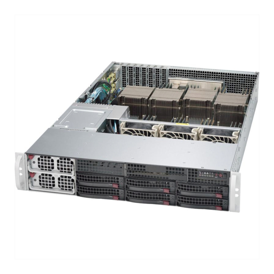
- Page 3 8028B-TR3F/C0R3FT Installation and maintainance should be performed by experienced technicians only. The SuperServer 8028B-TR3F/C0R3FT is a high-end server based on the SC828TS-R1K43LPB 2U rackmount chassis and the X10QBL-(CT) quad processor serverboard. The only difference between the two server models is that the...
- Page 4 SUPERSERVER 8028B-TR3F/C0R3FT User's Manual Chapter 5: Advanced Serverboard Setup Chapter 5 provides detailed information on the X10QBL-(CT) serverboard, including the locations and functions of connections, headers and jumpers. Refer to this chapter when adding or removing processors or main memory and when reconfiguring the serverboard.
- Page 5 Preface Notes...
-
Page 6: Table Of Contents
SUPERSERVER 8028B-TR3F/C0R3FT User's Manual Table of Contents Chapter 1 Introduction Overview ......................1-1 Serverboard Features ..................1-2 Processors ...................... 1-2 Memory ......................1-2 Serial ATA ....................... 1-2 SAS (8028B-C0R3FT Server Only) ..............1-2 Onboard Controllers/Ports ................1-3 Graphics Controller ..................1-3 Other Features .................... - Page 7 Table of Contents Rack Mounting Instructions ................2-4 Identifying the Sections of the Rack Rails ............2-4 Locking Tabs ....................2-5 Releasing the Inner Rail ................. 2-6 Installing The Inner Rails on the Chassis ............2-7 Installing the Outer Rails on the Rack ............2-8 Standard Chassis Installation .................
- Page 8 SUPERSERVER 8028B-TR3F/C0R3FT User's Manual Chapter 5 Advanced Serverboard Setup Handling the Serverboard ................5-1 Precautions ..................... 5-1 Unpacking ....................... 5-1 Connecting Cables ..................5-2 Connecting Data Cables ................. 5-2 Connecting Power Cables ................5-2 Connecting the Control Panel ................. 5-2 I/O Ports ......................
- Page 9 Table of Contents Chapter 6 Advanced Chassis Setup Static-Sensitive Devices .................. 6-1 Precautions ..................... 6-1 Unpacking ....................... 6-1 Control Panel ....................6-2 Removing the Chassis Cover ................. 6-2 Removing and Installing Chassis Fans ............6-4 Installing the Air Shroud .................. 6-6 Expansion Slot Setup ..................
- Page 10 SUPERSERVER 8028B-TR3F/C0R3FT User's Manual Notes...
-
Page 11: Chapter 1 Introduction
Chapter 1 Introduction Overview The SuperServer 8028B-TR3F/C0R3FT is a high-end server comprised of two main subsystems: the SC828TS-R1K43LPB 2U server chassis and the X10QBL-(CT) quad processor serverboard. Please refer to our web site for information on operating systems that have been certified for use with the system (www.supermicro. -
Page 12: Serverboard Features
SUPERSERVER 8028B-TR3F/C0R3FT User's Manual Serverboard Features At the heart of the SuperServer 8028B-TR3F/C0R3FT lies the X10QBL-(CT), a quad processor serverboard based on the Intel C602J chipset. Below are the main features of the X10QBL-(CT). (See Figure 1-1 for a block diagram of the chipset). -
Page 13: Onboard Controllers/Ports
BIOS rescue. Server Chassis Features The SuperServer 8028B-TR3F/C0R3FT is built upon the SC828TS-R1K43LPB chassis. Details on the chassis and on servicing procedures can be found in Chapter 6. The following is a general outline of the main features of the chassis. -
Page 14: Hard Drive Subsystem
(http://www.supermicro.com/products/). See section 5-6 for further details.) Front Control Panel The control panel on the SuperServer 8028B-TR3F/C0R3FT provides you with system monitoring and control. LEDs indicate system power, HDD activity, network activity, system overheat and power supply failure. A main power button and a system reset button are also included. -
Page 15: Advanced Power Management
Chapter 1: Introduction Advanced Power Management Intel® Intelligent Power Node Manager (NM) The Intel Intelligent Power Node Manager (IPNM) provides your system with ® real-time thermal control and power management for maximum energy efficiency. Although IPNM Specification Version 1.5 is supported by the BMC (Baseboard Management Controller), your system must also have IPNM-compatible Manageability Engine (ME) firmware installed to use this feature. -
Page 16: Contacting Supermicro
SUPERSERVER 8028B-TR3F/C0R3FT User's Manual Contacting Supermicro Headquarters Address: Super Micro Computer, Inc. 980 Rock Ave. San Jose, CA 95131 U.S.A. Tel: +1 (408) 503-8000 Fax: +1 (408) 503-8008 Email: marketing@supermicro.com (General Information) support@supermicro.com (Technical Support) Website: www.supermicro.com Europe Address: Super Micro Computer B.V. -
Page 17: Chapter 2 Server Installation
Rack and Server Precautions in the next section. Preparing for Setup The box the SuperServer 8028B-TR3F/C0R3FT was shipped in should include two sets of rail assemblies, two rail mounting brackets and the mounting screws you will need to install the system into the rack. Follow the steps in the order given to complete the installation process in a minimum amount of time. -
Page 18: Choosing A Setup Location
SUPERSERVER 8028B-TR3F/C0R3FT User's Manual Choosing a Setup Location • Leave enough clearance in front of the rack to enable you to open the front door completely (~25 inches) and approximately 30 inches of clearance in the back of the rack to allow for sufficient airflow and ease in servicing. -
Page 19: Rack Mounting Considerations
Chapter 2: Server Installation Rack Mounting Considerations Warning! To prevent bodily injury when mounting or servicing this unit in a rack, you must take special precautions to ensure that the system remains stable. The following guidelines are provided to ensure your safety: •... -
Page 20: Reliable Ground
SUPERSERVER 8028B-TR3F/C0R3FT User's Manual Reliable Ground A reliable ground must be maintained at all times. To ensure this, the rack itself should be grounded. Particular attention should be given to power supply connections other than the direct connections to the branch circuit (i.e. the use of power strips, etc.). -
Page 21: Locking Tabs
Chapter 2: Server Installation Figure 2-1: Identifying the Outer Rail, Middle Rail and Inner Rails (Left Rail Assembly Shown) Rail Assembly (Shown with Rails Outer Rail Retracted) Middle Rail Locking Tab Inner Rail This Side Faces Outward Locking Tabs Each inner rail has a locking tab. This tab locks the chassis into place when installed and pushed fully into the rack. -
Page 22: Releasing The Inner Rail
SUPERSERVER 8028B-TR3F/C0R3FT User's Manual Releasing the Inner Rail Releasing Inner Rail from the Outer Rails (Figure 2-2) 1. Identify the left and right outer rail assemblies as described on page 2-4. 2. Pull the inner rail out of the outer rail until it is fully extended as illustrated below. -
Page 23: Installing The Inner Rails On The Chassis
Chapter 2: Server Installation Installing The Inner Rails on the Chassis Installing the Inner Rails (Figures 2-3 and 2-4) 1. Confirm that the left and right inner rails have been correctly identified. 2. Place the inner rail firmly against the side of the chassis, aligning the hooks on the side of the chassis with the holes in the inner rail. -
Page 24: Installing The Outer Rails On The Rack
SUPERSERVER 8028B-TR3F/C0R3FT User's Manual Installing the Outer Rails on the Rack Installing the Outer Rails (Figure 2-5) 1. Press upward on the locking tab at the rear end of the middle rail. 2. Push the middle rail back into the outer rail. -
Page 25: Standard Chassis Installation
Chapter 2: Server Installation Standard Chassis Installation Installing the Chassis into a Rack (Figure 2-6) 1. Confirm that the inner rails are properly installed on the chassis. 2. Confirm that the outer rails are correctly installed on the rack. 3. Pull the middle rail out from the front of the outer rail and make sure that the ball-bearing shuttle is at the front locking position of the middle rail. -
Page 26: Optional Quick Installation Method
SUPERSERVER 8028B-TR3F/C0R3FT User's Manual Optional Quick Installation Method The following quick installation method may be used to install the chassis onto a rack. Installing the Chassis into a Rack 1. Install the whole rail assembly onto the rack as described on page 5-7. -
Page 27: Chapter 3 System Interface
Chapter 3: System Interface Chapter 3 System Interface Overview Most SC828 tower/4U rackmount chassis models have two buttons on the chassis a control panel; a reset button and an on/off switch. Figure 4-1: Front Control Panel Front Control Panel Control Panel Buttons There are two buttons located on the front of the chassis: a reset button and a power on/off button. -
Page 28: Control Panel Leds
SUPERSERVER 8028B-TR3F/C0R3FT User's Manual Control Panel LEDs The control panel located on the front of the chassis has several LEDs. These LEDs provide you with critical information related to different parts of the system. This section explains what each LED indicates when illuminated and any corrective action you may need to take. -
Page 29: Nic2 Led
Chapter 3: System Interface NIC2 LED Indicates network activity on the LAN2 port when flashing. NIC1 LED Indicates network activity on the LAN1 port when flashing. Power Fail LED This indicates a power failure to the system's power supply units. Drive Carrier LEDs The SC828 tower/4U rackmount chassis includes externally accessible SAS/SATA drives. - Page 30 SUPERSERVER 8028B-TR3F/C0R3FT User's Manual Notes...
-
Page 31: About Standardized Warning Statements
Only certified technicians should attempt to install or configure components. Read this appendix in its entirety before installing or configuring components in the Supermicro chassis. These warnings may also be found on our web site at http://www.supermicro.com/ about/policies/safety_information.cfm. Warning Definition Warning! This warning symbol means danger. - Page 32 SUPERSERVER 8028B-TR3F/C0R3FT User's Manual Warnung WICHTIGE SICHERHEITSHINWEISE Dieses Warnsymbol bedeutet Gefahr. Sie befinden sich in einer Situation, die zu Verletzungen führen kann. Machen Sie sich vor der Arbeit mit Geräten mit den Gefahren elektrischer Schaltungen und den üblichen Verfahren zur Vorbeugung vor Unfällen vertraut.
- Page 33 Warning Statements for AC Systems جسذٌة اصابة ًتتسبب ف حالة ٌوكي أى ًاًك ف خطز ًٌٌع هذا الزهز !تحذٌز الذوائز بالوخاطز الٌاجوة عي ي على علن ، ك هعذات تعول على أي قبل أى الكهزبائٍة حىادث أي وقىع وٌع ل الىقائٍة...
-
Page 34: Installation Instructions
SUPERSERVER 8028B-TR3F/C0R3FT User's Manual Installation Instructions Warning! Read the installation instructions before connecting the system to the power source. 設置手順書 システムを電源に接続する前に、 設置手順書をお読み下さい。 警告 将此系统连接电源前,请先阅读安装说明。 警告 將系統與電源連接前,請先閱讀安裝說明。 Warnung Vor dem Anschließen des Systems an die Stromquelle die Installationsanweisungen lesen. ¡Advertencia! Lea las instrucciones de instalación antes de conectar el sistema a la red de alimentación. -
Page 35: Circuit Breaker
Chapter 4: Warning Statements for AC Systems Circuit Breaker Warning! This product relies on the building's installation for short-circuit (overcurrent) protection. Ensure that the protective device is rated not greater than: 250 V, 20 A. サーキッ ト ・ ブレーカー この製品は、 短絡 (過電流) 保護装置がある建物での設置を前提としています。 保護装置の定格が250 V、... -
Page 36: Power Disconnection Warning
SUPERSERVER 8028B-TR3F/C0R3FT User's Manual في التي تم تثبيتها مه الدوائرالقصيرة الحمايت معداث يعتمد على هذا المنتج المبنى أكثر من ليس وقائي ال الجهاز تقييم أن تأكد من 20A, 250V 경고! 이 제품은 전원의 단락(과전류)방지에 대해서 전적으로 건물의 관련 설비에 의존합니다. 보호장치의 정격이 반드시 250V(볼트), 20A(암페어)를 초과하지... - Page 37 Chapter 4: Warning Statements for AC Systems Warnung Das System muss von allen Quellen der Energie und vom Netzanschlusskabel getrennt sein, das von den Spg.Versorgungsteilmodulen entfernt wird, bevor es auf den Chassisinnenraum zurückgreift, um Systemsbestandteile anzubringen oder zu entfernen. ¡Advertencia! El sistema debe ser disconnected de todas las fuentes de energía y del cable eléctrico quitado de los módulos de fuente de alimentación antes de tener acceso el interior del chasis para instalar o para quitar componentes de sistema.
-
Page 38: Equipment Installation
SUPERSERVER 8028B-TR3F/C0R3FT User's Manual Equipment Installation Warning! Only trained and qualified personnel should be allowed to install, replace, or service this equipment. 機器の設置 トレーニングを受け認定された人だけがこの装置の設置、 交換、 またはサービスを許可 されています。 警告 只有经过培训且具有资格的人员才能进行此设备的安装、更换和维修。 警告 只有經過受訓且具資格人員才可安裝、更換與維修此設備。 Warnung Das Installieren, Ersetzen oder Bedienen dieser Ausrüstung sollte nur geschultem, qualifiziertem Personal gestattet werden. -
Page 39: Restricted Area
Chapter 4: Warning Statements for AC Systems Waarschuwing Deze apparatuur mag alleen worden geïnstalleerd, vervangen of hersteld door geschoold en gekwalificeerd personeel. Restricted Area Warning! This unit is intended for installation in restricted access areas. A restricted access area can be accessed only through the use of a special tool, lock and key, or other means of security. -
Page 40: Battery Handling
SUPERSERVER 8028B-TR3F/C0R3FT User's Manual אזור עם גישה מוגבלת !אזהרה יש להתקין את היחידה באזורים שיש בהם הגבלת גישה. הגישה ניתנת בעזרת .)'כלי אבטחה בלבד (מפתח, מנעול וכד محظورة مناطق ٍنتركُبها ف هذه انىحذة تخصيص تم ،أداة خاصت من خالل استخذاو... - Page 41 Chapter 4: Warning Statements for AC Systems Warnung Bei Einsetzen einer falschen Batterie besteht Explosionsgefahr. Ersetzen Sie die Batterie nur durch den gleichen oder vom Hersteller empfohlenen Batterietyp. Entsorgen Sie die benutzten Batterien nach den Anweisungen des Herstellers. Attention Danger d'explosion si la pile n'est pas remplacée correctement. Ne la remplacer que par une pile de type semblable ou équivalent, recommandée par le fabricant.
-
Page 42: Redundant Power Supplies
SUPERSERVER 8028B-TR3F/C0R3FT User's Manual Redundant Power Supplies Warning! This unit might have more than one power supply connection. All connections must be removed to de-energize the unit. 冗長電源装置 このユニッ トは複数の電源装置が接続されている場合があります。 ユニッ トの電源を切るためには、 すべての接続を取り外さなければなりません。 警告 此部件连接的电源可能不止一个,必须将所有电源断开才能停止给该部件供电。 警告 此裝置連接的電源可能不只一個,必須切斷所有電源才能停止對該裝置的供電。 Warnung Dieses Gerät kann mehr als eine Stromzufuhr haben. Um sicherzustellen, dass der Einheit kein trom zugeführt wird, müssen alle Verbindungen entfernt werden. -
Page 43: Backplane Voltage
Chapter 4: Warning Statements for AC Systems امداد الطاقة بوحدات عدة اتصاالت جهاز ال يكون لهذا قد الكهرباء عن وحدة ال لعسل كافة االتصاالت يجب إزالة 경고! 이 장치에는 한 개 이상의 전원 공급 단자가 연결되어 있을 수 있습니다. 이 장치에 전원을... -
Page 44: Comply With Local And National Electrical Codes
SUPERSERVER 8028B-TR3F/C0R3FT User's Manual Attention Lorsque le système est en fonctionnement, des tensions électriques circulent sur le fond de panier. Prendre des précautions lors de la maintenance. מתח בפנל האחורי !הרה אז קיימת סכנת מתח בפנל האחורי בזמן תפעול המערכת. יש להיזהר במהלך... -
Page 45: Product Disposal
Chapter 4: Warning Statements for AC Systems ¡Advertencia! La instalacion del equipo debe cumplir con las normas de electricidad locales y nacionales.Attention L'équipement doit être installé conformément aux normes électriques nationales et locales. תיאום חוקי החשמל הארצי !אזהרה הציוד חייבת להיות תואמת לחוקי החשמל המקומיים והארציים התקנת... -
Page 46: Hot Swap Fan Warning
SUPERSERVER 8028B-TR3F/C0R3FT User's Manual Warnung Die Entsorgung dieses Produkts sollte gemäß allen Bestimmungen und Gesetzen des Landes erfolgen. ¡Advertencia! Al deshacerse por completo de este producto debe seguir todas las leyes y reglamentos nacionales. Attention La mise au rebut ou le recyclage de ce produit sont généralement soumis à des lois et/ou directives de respect de l'environnement. - Page 47 Chapter 4: Warning Statements for AC Systems 当您从机架移除风扇装置,风扇可能仍在转动。小心不要将手指、螺丝起子和其他 物品太靠近风扇 警告 當您從機架移除風扇裝置,風扇可能仍在轉動。小心不要將手指、螺絲起子和其他 物品太靠近風扇。 Warnung Die Lüfter drehen sich u. U. noch, wenn die Lüfterbaugruppe aus dem Chassis genommen wird. Halten Sie Finger, Schraubendreher und andere Gegenstände von den Öffnungen des Lüftergehäuses entfernt. ¡Advertencia! Los ventiladores podran dar vuelta cuando usted quite ell montaje del ventilador del chasis.
-
Page 48: Power Cable And Ac Adapter
Electrical Appliance and Material Safety Law prohibits the use of UL or CSA -certified cables (that have UL/CSA shown on the code) for any other electrical devices than products designated by Supermicro only. 電源コードとACアダプター 製品を設置する場合、 提供または指定された接続ケーブル、 電源コードとACアダプター... - Page 49 Appareils électroménagers et de loi sur la sécurité Matériel interdit l'utilisation de UL ou CSA câbles certifiés qui ont UL ou CSA indiqué sur le code pour tous les autres appareils électriques que les produits désignés par Supermicro seulement.
- Page 50 Elektrisch apparaat en veiligheidsinformatiebladen wet verbiedt het gebruik van UL of CSA gecertificeerde kabels die UL of CSA die op de code voor andere elektrische apparaten dan de producten die door Supermicro alleen. 4-20...
-
Page 51: Chapter 5 Advanced Serverboard Setup
Chapter 5: Advanced Serverboard Setup Chapter 5 Advanced Serverboard Setup This chapter covers the steps required to install the X10QBL-(CT) serverboard into the chassis, connect the data and power cables and install add-on cards. All serverboard jumpers and connections are also described. A layout and quick reference chart are included in this chapter for your reference. -
Page 52: Connecting Cables
SUPERSERVER 8028B-TR3F/C0R3FT User's Manual Connecting Cables Now that the serverboard is installed, the next step is to connect the cables to the board. These include the data (ribbon) cables for the peripherals and control panel and the power cables. Connecting Data Cables... - Page 53 Chapter 5: Advanced Serverboard Setup Figure 5-1. Control Panel Header Pins Ground FP PWRLED 3.3 V UID Switch HDD LED NIC1 Link LED NIC1 Activity LED NIC2 Activity LED NIC2 Link LED OH/Fan Fail/ UID LED PWR Fail LED) Power Fail LED 3.3V Reset Reset Button...
-
Page 54: I/O Ports
SUPERSERVER 8028B-TR3F/C0R3FT User's Manual I/O Ports The I/O ports are color coded in conformance with the PC 99 specification. See Figure 5-2 below for the colors and locations of the various I/O ports. Figure 5-2. I/O Ports I/O Ports COM Port Back Panel (Vertical) USB 2.0 Port 2... -
Page 55: Installing The Processor And Heatsink
CPU socket cap is in place, and none of the socket pins are bent; otherwise, contact your retailer immediately. 5. Refer to the Supermicro website for updates on CPU support. 6. With the CPU inside the socket, inspect the four corners of the CPU to make sure that the CPU is properly installed. - Page 56 SUPERSERVER 8028B-TR3F/C0R3FT User's Manual Note: All graphics, drawings and pictures shown in this manual are for illustration only. The components that came with your machine may or may not look exactly the same as those shown in this manual. 2. Press the second load lever labeled 'Close 1st' to release the load plate that covers the CPU socket from its locking position.
- Page 57 Chapter 5: Advanced Serverboard Setup 4. Use your thumb and the index finger to loosen the lever and open the load plate. 5. Using your thumb and index finger, hold the CPU on its edges. Align the CPU keys, which are semi-circle cutouts, against the socket keys. Socket Keys CPU Keys 6.
- Page 58 SUPERSERVER 8028B-TR3F/C0R3FT User's Manual 7. With the CPU inside the socket, inspect the four corners of the CPU to make sure that the CPU is properly installed. Push down and lock the Gently close the load plate. lever labeled 'Close 1st'.
-
Page 59: Installing A Passive Cpu Heatsink
Chapter 5: Advanced Serverboard Setup Installing a Passive CPU Heatsink 1. Do not apply any thermal grease to the heatsink or the CPU die -- the required amount has already been applied. 2. Place the heatsink on top of the CPU so that the four mounting holes are aligned with those on the Motherboard's and the Heatsink Bracket underneath. -
Page 60: Removing The Heatsink
SUPERSERVER 8028B-TR3F/C0R3FT User's Manual Removing the Heatsink Caution: We do not recommend that the CPU or the heatsink be removed. However, if you do need to uninstall the heatsink, please follow the instructions below to uninstall the heatsink to prevent damage done to the CPU or the CPU socket. -
Page 61: Installing Memory
Use memory modules of the same type, speed, timing and same on a serverboard. For the latest memory updates, please refer to our website a at http://www.supermicro.com/products/motherboard. Notes: 1. For best system performance, we recommend that a pair of CPUs (CPU1/ CPU2) or two pairs of CPUs (CPU1/CPU2/CPU3/CPU4) be installed. -
Page 62: Processor & Memory Module Population Configuration
SUPERSERVER 8028B-TR3F/C0R3FT User's Manual Processor & Memory Module Population Configuration For memory to work properly, follow the tables below for memory installation. Fully-Populated Configuration Please follow the instructions below to populate all DIMM slots: Processors and their Corresponding Memory Modules... -
Page 63: Populating Memory Modules
32GB 64GB 1066 1066 Note: For detailed information on memory support and updates, please refer to the SMC Recommended Memory List posted on our website at http://www.supermicro.com/ support/resources/mem.cfm. RDIMM/LRDIMM DDR3 ECC in Lockstep Mode (1:1) Type Ranks Memory Max Speed (Ghz); Voltage (V) -
Page 64: Other Important Notes And Restrictions
SUPERSERVER 8028B-TR3F/C0R3FT User's Manual Other Important Notes and Restrictions • For the memory modules to work properly, please install DIMM modules of the same type, same speed and same operating frequency on the motherboard. Mixing of RDIMMs or LRDIMMs is not allowed. -
Page 65: Serverboard Details
Chapter 5: Advanced Serverboard Setup Serverboard Details Figure 5-4. X10QBL-(CT) Layout USB0/1 USB2 COM1 LED1 LEDBMC FAN9 IPMI_LAN LAN CTRL LAN1/2 FAN10 JPTG1 MAC CODE IPMI CODE BAR CODE SAS CODE JBT1 USB4/5 X10QBL-CT USB6/7 IB CODE BIOS CPU4 CPU2 CLOSE 1st CMOS OPEN 1st... - Page 66 SUPERSERVER 8028B-TR3F/C0R3FT User's Manual X10QBL-(CT) Quick Reference Jumper Description Default Setting JBT1 Clear CMOS See Chapter 2 C1/JI SMB to PCI-E slots Off (Disabled) JPB1 BMC Enable Pins 1-2 (Enabled) JPG1 VGA Enable Pins 1-2 (Enabled) JPL1 GLAN1/GLAN2 Enable (X10QBL)
- Page 67 Chapter 5: Advanced Serverboard Setup Connector Description BT2 (Battery) Onboard CMOS Battery (See Chpt. 3 for used battery disposal.) COM1/COM2 Back panel COM port 1/Serial port 2 header FAN1-FAN10 CPU/System fan headers I-SATA0-5 Intel SATA 3.0/2.0 ports 0-5 (I-SATA 3.0 ports 0/1, I-SATA 2.0 ports 2-5) (supported by Intel PCH) Speaker/Power LED header Front Panel Control header...
-
Page 68: Connector Definitions
SUPERSERVER 8028B-TR3F/C0R3FT User's Manual Connector Definitions Main ATX Power Supply Connector ATX Power 24-pin Connector Pin Definitions A 24-pin main power supply connector Pin# Definition Pin # Definition ( J P W R 1 ) , a n d f o u r 8 - p i n C P U power connectors (JPWR2/JPWR3/ +3.3V... - Page 69 Chapter 5: Advanced Serverboard Setup Reset Button Reset Button Pin Definitions (JF1) The Reset Button connection is located Pin# Definition on pins 3 and 4 of JF1. Attach it to a hardware reset switch on the computer Reset case. Refer to the table on the right for Ground pin definitions.
- Page 70 SUPERSERVER 8028B-TR3F/C0R3FT User's Manual HDD/UID LED HDD LED Pin Definitions (JF1) The HDD LED connection is located on Pin# Definition pins 13 and 14 of JF1. Attach a cable UID LED here to indicate HDD activity and UID status. See the table on the right for HD Active pin definitions.
- Page 71 Chapter 5: Advanced Serverboard Setup Universal Serial Bus (USB) Back Panel USB 2.0 (USB 0/1 Pin Definitions Three USB2.0 ports (USB 0/1, USB Pin# Definition Pin# Definition 2) are located on the I/O back panel. Two internal USB headers, located USB_PN1 USB_PN0 next to the I-SATA ports 4/5, provide...
- Page 72 SUPERSERVER 8028B-TR3F/C0R3FT User's Manual Unit Identifier Switch UID Switch A rear Unit Identifier (UID) switch Pin# Definition (JUIDB1) and a rear LED (LE1) are Ground located close to LAN ports 1/2 on Ground the rear side of the motherboard. The...
- Page 73 Chapter 5: Advanced Serverboard Setup IPMB Header IPMB Header Pin Definitions A System Management Bus header for Pin# Definition IPMI 2.0 is located at JIPMB1. Connect Data an appropriate cable here to use the IPMB I C connection on your system. Ground Clock No Connection...
- Page 74 SUPERSERVER 8028B-TR3F/C0R3FT User's Manual SATA DOM Power Connectors DOM PWR Pin Definitions Two power connectors for SATA DOM Pin# Definition (Disk_On_Module) devices are located at JSD1/JSD2. Connect appropriate cables here to provide power support Ground for your Serial-Link DOM devices.
-
Page 75: Jumper Settings
Chapter 5: Advanced Serverboard Setup Jumper Settings Connector Pins Explanation of Jumpers To modify the operation of the Jumper motherboard, jumpers can be used to choose between optional settings. Jumpers create shorts between two Setting pins to change the function of the connector. - Page 76 SUPERSERVER 8028B-TR3F/C0R3FT User's Manual LAN Enable/Disable LAN1/2 Enable/Disable Jumper Settings JPL1 enables or disables Gigabit_LAN Jumper Setting Definition ports on the X10QBL-CT, while JPTG1 Pins 1-2 Enabled enables or disables 10G-LAN ports on the X10QBL-T. See the table on the...
- Page 77 Chapter 5: Advanced Serverboard Setup C Bus to PCI-Exp. Slots C for PCI-E slots Jumper Settings Use Jumpers JI C1 and JI C2 to Jumper Setting Definition connect the System Management Normal (Default) Bus (I C) to the PCI-Express slots to improve PCI performance.
-
Page 78: 5-10 Onboard Indicators
SUPERSERVER 8028B-TR3F/C0R3FT User's Manual 5-10 Onboard Indicators GLAN LEDs GLAN LED Activity Link Speed There are two LAN ports (LAN1/2) on the motherboard. Each Ethernet LAN port has two LEDs. The Yellow LED GLAN Activity Indicator on the right indicates connection and (Right) LED Settings activity. - Page 79 Chapter 5: Advanced Serverboard Setup Onboard Power LED Onboard PWR LED Indicator LED States An Onboard Power LED indicator LED Color Definition is located at LED15 (LEDPWR) on System Off the motherboard. When this LED is (PWR cable not connected) on, the system is on.
-
Page 80: 5-11 Sas/Sata Ports
SUPERSERVER 8028B-TR3F/C0R3FT User's Manual 5-11 SAS/SATA Ports SATA 3.0 Ports Six SATA connections supported by Intel PCH 602 are located on the motherboard. I-SATA ports 0/1 support SATA 3.0 connections, while I-SATA ports 2-5 support SATA 2.0. These SATA connectors provide serial-link connections, which are faster than Parallel ATA connections. -
Page 81: 5-12 Installing Software
Chapter 5: Advanced Serverboard Setup 5-12 Installing Software The Supermicro ftp site contains drivers and utilities for your system at ftp://ftp. supermicro.com. Some of these must be installed, such as the chipset driver. After accessing the ftp site, go into the CDR_Images directory and locate the ISO file for your motherboard. -
Page 82: Superdoctor 5
SUPERSERVER 8028B-TR3F/C0R3FT User's Manual Note: Click the icons showing a hand writing on paper to view the readme files for each item. Click the computer icons to the right of these items to install each item (from top to the bottom) one at a time. After installing each item, you must re-boot the system before moving on to the next item on the list. - Page 83 Figure 5-7. SuperDoctor 5 Interface Display Screen (Remote Control) Note: The SuperDoctor 5 program and User’s Manual can be downloaded from the Supermicro web site at http://www.supermicro.com/products/nfo/sms_sd5.cfm. For Linux, we recommend that you use the SuperDoctor II application instead. 5-33...
-
Page 84: 5-13 Serverboard Battery
SUPERSERVER 8028B-TR3F/C0R3FT User's Manual 5-13 Serverboard Battery Caution: There is a danger of explosion if the onboard battery is installed upside down, which will reverse its polarites (see Figure 5-8). This battery must be replaced only with the same or an equivalent type recommended by the manufacturer (CR2032). -
Page 85: Chapter 6 Advanced Chassis Setup
Chapter 6: Advanced Chassis Setup Chapter 6 Advanced Chassis Setup This chapter covers the steps required to install components and perform maintenance on the SC828TS-R1K43LPB chassis. For component installation, follow the steps in the order given to eliminate the most common problems encountered. -
Page 86: Control Panel
SUPERSERVER 8028B-TR3F/C0R3FT User's Manual Figure 6-1. Front and Rear Chassis Views Control Panel Power Supplies (2) SATA Drives (6) COM1 Port VGA Port IPMI LAN USB Ports Expansion Slots (4) Ethernet Ports Control Panel The control panel (located on the front of the chassis) must be connected to the JF1 connector on the serverboard to provide you with system status indications. - Page 87 Chapter 6: Advanced Chassis Setup 4. Slide the cover back. 5. Lift the cover upwards Figure 6-2: Removing the Chassis Cover Figure 6-3: Lifting the Chassis Cover...
-
Page 88: Removing And Installing Chassis Fans
SUPERSERVER 8028B-TR3F/C0R3FT User's Manual Removing and Installing Chassis Fans The SC828 chassis comes equipped with three 9500 RPM fans for optimal cooling. These fans are NOT redundant, hot-plug and must be replaced when they fail.. In the unlikely event that a fan needs to be replaced, removing and installing chassis fans is a simple procedure. - Page 89 Chapter 6: Advanced Chassis Setup Installing a Chassis Fan (Figure 6-5) 6. Slide the fan housing into the chassis fan mounting bracket. 7. Push down gently on the top of the fan until it clicks into place 8. Reconnect the fan wiring to the connectors. 9.
-
Page 90: Installing The Air Shroud
SUPERSERVER 8028B-TR3F/C0R3FT User's Manual Installing the Air Shroud The air shroud is used to channel the air flow from the system fans and direct it into critical areas of the chassis that require cooling. The SC828 chassis comes equipped with an optimized air shroud, which allows the direction of the airflow to be fine-tuned for optimal cooling. -
Page 91: Expansion Slot Setup
Chapter 6: Advanced Chassis Setup Expansion Slot Setup The SC828 chassis includes four slots for expansion cards. Installing an Expansion Card (Figure 6-7) 1. Confirm that each expansion card includes a standard L-bracket. 2. Disconnect the power supply, lay the chassis on a flat surface and open the chassis cover. -
Page 92: Removing The Hard Drive Tray And Installing A Hard Drive
SUPERSERVER 8028B-TR3F/C0R3FT User's Manual Removing the Hard Drive Tray and Installing a Hard Drive To install a hard disk drive into the chassis, it is necessary to remove the HDD carrier from the chassis. Removing a Hard Drive Carrier 1. Press the release tab on the front of each hard drive try to unlock the HDD carrier. - Page 93 Chapter 6: Advanced Chassis Setup Replacing a Hard Drive in the Hard Drive Carrier (Figure 6-9 & Figure 6-10) 1. Remove the two screws that attach to the both sides of the dummy HDD. 2. Slide out the dummy HDD as shown Figure 6-9: Removing the Dummy Hard Drive 3.
-
Page 94: Power Supply
240V input voltage. In the unlikely event that a power supply unit fails, the system will shut down and you will need to change the power supply unit. New units can be ordered directly from Supermicro (see contact information in the Preface). The SC828 chassis power supplies are NOT redundant, hot-plug power supplies. - Page 95 Chapter 6: Advanced Chassis Setup Figure 6-12: Releasing the Power Supply Release Button Handle 4. Gently pull the power supply forward and out of the chassis (Figure 6-13). Figure 6-13: Removing the Power Supply 6-11...
-
Page 96: Installing The Power Supply
SUPERSERVER 8028B-TR3F/C0R3FT User's Manual Installing the Power Supply Power Supply Installation 1. Unplug all power leading to the chassis. 2. Insert the power supply into its slot in the front of the chassis, gently pushing it back into the chassis until it clicks into position (Figure 6-14). -
Page 97: Chapter 7 Bios
Chapter 7: BIOS Chapter 7 BIOS Introduction This chapter describes the AMI BIOS Setup Utility for the SuperServer 8028B-TR3F/C0R3FT. The 16 MB SPI AMI BIOS® SM Flash BIOS is stored in a Flash EEPROM and can be easily updated. This chapter describes the basic navigation of the AMI BIOS Setup Utility setup screens. -
Page 98: Main Setup
SUPERSERVER 8028B-TR3F/C0R3FT User's Manual Main Setup When you first enter the AMI BIOS setup utility, you will enter the Main setup screen. You can always return to the Main setup screen by selecting the Main tab on the top of the screen. The Main BIOS Setup screen is shown below. -
Page 99: Advanced Setup Configurations
Chapter 7: BIOS Memory Information Total Memory This item displays the amount of memory that is available in the system. Advanced Setup Configurations Select the Advanced tab to access the following submenu items. Boot Features Boot Configuration Quiet Boot Use this item to select bootup screen display between POST messages and the OEM logo. - Page 100 SUPERSERVER 8028B-TR3F/C0R3FT User's Manual AddOn ROM Display Mode Use this item to set the display mode for the Option ROM. Select Keep Current to use the current AddOn ROM Display setting. Select Force BIOS to use the Option ROM display set by the system BIOS. The options are Force BIOS and Keep Current.
- Page 101 Chapter 7: BIOS Restore on AC Power Loss Use this item to set the power state after a power outage. Select Stay Off for the system power to remain off after a power outage. Select Power On to turn on the system power after a power outage.
- Page 102 SUPERSERVER 8028B-TR3F/C0R3FT User's Manual Clock Spread Spectrum Select Enable to allow the BIOS to monitor and attempt to reduce the level of Electromagnetic Interference caused by the components whenever needed. The options are Disable and Enable. Cores Enabled This feature allows the user to set the number of CPU cores to enable. Enter "0"...
- Page 103 Chapter 7: BIOS DCU (Data Cache Unit) Streamer Prefetcher (Available when supported by the CPU) If this item is set to Enable, the DCU Streamer Prefetcher will prefetch data streams from the cache memory to the DCU (Data Cache Unit) to speed up data accessing and processing for CPU performance enhancement.
- Page 104 SUPERSERVER 8028B-TR3F/C0R3FT User's Manual CPU P State Control EIST EIST (Enhanced Intel SpeedStep Technology) allows the system to automatically adjust processor voltage and core frequency to reduce power consumption and heat dissipation. The options are Disabled, and Enabled. Turbo Mode (Available when Intel® EIST Technology is enabled) Select Enabled to use the Turbo Mode to boost system performance.
- Page 105 Chapter 7: BIOS Monitor/Mwait Select Enabled to enable the Monitor/MWait instructions. The Monitor instruction monitors a region of memory for writes, and MWait instructions instruct the CPU to stop until the monitored region begins to write. The options are Enable and Disable.
- Page 106 SUPERSERVER 8028B-TR3F/C0R3FT User's Manual Chipset Configuration North Bridge This feature is used to configure Intel North Bridge settings. Integrated IO Configuration EV DFX (Device Function On-Hide) Features When this feature is set to Enable, the EV_DFX Lock Bits that are located inside a processor will always remain clear during electric tuning.
- Page 107 Chapter 7: BIOS LAN1/2 Use the items below to configure the PCI-E settings for a PCI-E port specified by the user. The following items will display: • PCI-E Port Link Status • PCI-E Port Link Max • PCI-E Port Link Speed Link Speed Use this item to select the PCI-E link speed for the PCI-E port specified by the user.
- Page 108 SUPERSERVER 8028B-TR3F/C0R3FT User's Manual IOAT (Intel® IO Acceleration) Configuration Enable IOAT Select Enable to enable Intel I/OAT (I/O Acceleration Technology) support, which will significantly reduce CPU overhead by leveraging CPU architectural improvements and freeing the system resource for other tasks. The options are Enable and Disable.
- Page 109 Chapter 7: BIOS QPI (Quick Path Interconnect) Configuration QPI General Configuration QPI Status The following information will display: • Number of CPU • Number of IIO • LInk Speed • Current QPI Link Frequency • QPI Global MMIO Low Base/Limit •...
- Page 110 SUPERSERVER 8028B-TR3F/C0R3FT User's Manual QPI Per Socket Configuration CPU 0/CPU 1 IO Resource Allocation Ratio Use this feature to set the IO resource-allocation ratio (from 0-8). The default setting is 1. MMIOL Resource Allocation Ratio Use this feature to set the Memory-Mapped IO resource-allocation ratio (from 0-8).
- Page 111 Chapter 7: BIOS LRDIMM (Load-Reduction DIMM) Module Delay When this item is set to Disabled, the MRC (Memory Regulator Controller) will not use SPD bytes 90-95 for module delay on LRDIMM memory. The options are Disabled and Auto. Data Scrambling Select Enabled to enable data scrambling to enhance system performance and data integrity.
- Page 112 SUPERSERVER 8028B-TR3F/C0R3FT User's Manual Memory Topology This item displays the status of each DIMM module as detected by the BIOS. • Jordon Creek Revision ID • Node • Channel • DIMM Frequency Memory RAS (Reliability_Availability_Serviceability) Configuration (Available when a DIMM module is detected in a memory slot specified) Use this submenu to configure the following Memory RAS settings.
- Page 113 Chapter 7: BIOS Leaky Bucket High Bit Use this feature to set the High Bit value for the Leaky Bucket algorithm which is used to check the data transmissions between CPU sockets and the memory controller. The default setting is 41. Memory Interleaving Use this feature to set the DIMM memory interleaving mood.
- Page 114 SUPERSERVER 8028B-TR3F/C0R3FT User's Manual DDDC Wirekill Select Enabled for Double-Device Data Correction (DDDC) Wire-kill support which will disable the wire connection between two DRAM devices when they fail. The options are Disabled and Enable. DDDC Wirekill Threshold Use this feature to set the DDDC Wirekill threshold. When the memory errors reach the threshold,wire-connections between the failed DRAM modules will be disconnected.
- Page 115 Chapter 7: BIOS Port 60/64 Emulation Select Enabled for I/O port 60h/64h emulation support which will provide complete USB keyboard legacy support for the operating system that does not support Legacy USB devices. The options are Disabled and Enabled. USB Controller 0 Enable Select Enabled to enable USB Controller 0 which supports USB Port 0 to Port 7.
- Page 116 SUPERSERVER 8028B-TR3F/C0R3FT User's Manual SATA Port 0~ Port 5 This item displays the information detected on the installed SATA drive on the particular SATA port. • Display of drive number and capacity as detected by the BIOS • Software Preserve Port 0~ Port 5 Select Enabled to enable a SATA port specified by the user.
- Page 117 Chapter 7: BIOS Serial ATA Port 0~ Port 5 This item displays the information detected on the installed SATA drives on the particular SATA port. • Display of drive number and capacity as detected by the BIOS • Software Preserve Support Port 0~ Port 5 Select Enabled to enable a SATA port specified by the user.
- Page 118 SUPERSERVER 8028B-TR3F/C0R3FT User's Manual SR-IOV Support (Available if the system supports Single-Root Virtualization) Select Enabled for Single-Root IO Virtualization support. The options are Enabled and Disabled. Maximum Payload Select Auto to allow the system BIOS to automatically set the maximum payload value for a PCI-E device to enhance system performance.
- Page 119 Chapter 7: BIOS Warning: Enabling ASPM support may cause some PCI-E devices to fail! PCI Devices Option ROM Settiing CPU1 SLOT1 PCI-E 3.0 x8 OPROM/CPU1 SLOT2 PCI-E 3.0 x16 OPROM/ CPU2 SLOT3 PCI-E 3.0 x8 OPROM/CPU2 SLOT4 PCI-E 3.0 x16 OPROM/ Use this feature to select the type of device installed on a slot specified by the user for the system to boot from.
- Page 120 SUPERSERVER 8028B-TR3F/C0R3FT User's Manual WHEA Support Select Enabled to support the Windows Hardware Error Architecture (WHEA) platform and provide a common infrastructure for the system to handle hardware errors within the Windows OS environment to reduce system crashes and to enhance system recovery and health monitoring.
- Page 121 Chapter 7: BIOS Intel TXT Support Select Enabled for Intel Trusted Execution Technology support. The options are Enabled and Disabled. ME (Management Engine) Subsystem This feature displays the following ME Subsystem Configuration settings. General ME Configuration Operational Firmware Version Recovery Firmware Version ME Firmware Features ME Firmware Status #1 ME Firmware Status #2...
- Page 122 SUPERSERVER 8028B-TR3F/C0R3FT User's Manual Serial Port 2 Configuration Serial Port Select Enabled to enable a serial port specified by the user. The options are Enabled and Disabled. Change Port 2 Settings This option specifies the base I/O port address and the Interrupt Request address of Serial Port 2 (SOL).
- Page 123 Chapter 7: BIOS Bits Per second Use this item to set the transmission speed for a serial port used in Console Redirection. Make sure that the same speed is used in the host computer and the client computer. A lower transmission speed may be required for long and busy lines.
- Page 124 SUPERSERVER 8028B-TR3F/C0R3FT User's Manual Legacy OS Redirection Resolution Use this item to select the number of rows and columns used in Console Redirection for legacy OS support. The options are 80x24 and 80x25. Putty KeyPad This feature selects Function Keys and KeyPad settings for Putty, which is a terminal emulator designed for the Windows OS.
- Page 125 Chapter 7: BIOS Bits Per second Use this feature to set the transmission speed for a serial port used in Console Redirection. Make sure that the same speed is used in the host computer and the client computer. A lower transmission speed may be required for long and busy lines.
-
Page 126: Event Logs
SUPERSERVER 8028B-TR3F/C0R3FT User's Manual Legacy OS Redirection Resolution Use this feature to select the number of rows and columns used in Console Redirection for legacy OS support. The options are 80x24 and 80x25. Putty KeyPad This feature selects Function Keys and KeyPad settings for Putty, which is a terminal emulator designed for the Windows OS. - Page 127 Chapter 7: BIOS PCI-Ex Error Enable Select Enabled for the BIOS to correct errors occurred in the PCI-E slots. The options are Enabled and Disabled. Memory Corrected Error Enabling Select Enabled for the BIOS to correct a memory error if it is correctable. The options are Enabled and Disabled.
- Page 128 SUPERSERVER 8028B-TR3F/C0R3FT User's Manual METW (Multiple Event Count Time Window) This item allows the user to decide how long (in minutes) should the multiple event counter wait before generating a new event log. Enter a number from 0 to 99. The default setting is 60.
-
Page 129: Ipmi
Chapter 7: BIOS IPMI Select the IPMI (Intelligent Platform Management Interface) tab to access the following submenu items. These items indicates your system IPMI firmware revision number and status. • IPMI Firmware Revision • IPMI Status System Event Log Enabling/Disabling Options SEL Components Select Enabled to enable all system event logging support at bootup. - Page 130 SUPERSERVER 8028B-TR3F/C0R3FT User's Manual Erasing Settings Erase SEL Select Yes, On next reset to erase all system event logs upon next system reboot. Select Yes, On every reset to erase all system event logs upon each system reboot. Select No to keep all system event logs after each system reboot. The options are No, Yes, On next reset, and Yes, On every reset.
- Page 131 Chapter 7: BIOS Station MAC Address This item displays the Station MAC address for this computer. Mac addresses are 6 two-digit hexadecimal numbers. Gateway IP Address This item displays the Gateway IP address for this computer. This should be in decimal and in dotted quad form (i.e., 192.168.10.253).
-
Page 132: Security
SUPERSERVER 8028B-TR3F/C0R3FT User's Manual Security This menu allows the user to configure the following security settings for the system. Administrator Password Use this item to set the administrator password which is required to enter the BIOS setup utility. The length of the password should be from 3 characters to 20 characters long. -
Page 133: Boot
Chapter 7: BIOS Boot This submenu allows the user to configure the following boot settings for the system. Boot Mood Select Use this item to configure boot mood select settings for the machine. The options are Legacy, UEFI, and Dual. Fixed Boot Order Priorities This option prioritizes the order of bootable devices that the system to boot from. - Page 134 SUPERSERVER 8028B-TR3F/C0R3FT User's Manual Delete Driver Option Use this item to select a driver to delete from the boot priority list. Delete Driver Option Select the target driver to delete. Network Drive BBS Priorities (Available when a device is installed in this drive) This item sets the boot sequence of available network boot drives.
-
Page 135: Save & Exit
Chapter 7: BIOS Save & Exit This submenu allows the user to configure the Save and Exit settings for the system. Save Changes and Exit When completing the system configuration changes, select this option to save the changes and exit from the BIOS setup utility. When a dialog box appears, asking you if you want to save configuration and exit, select Yes to save the changes and exit from the BIOS setup utility. - Page 136 SUPERSERVER 8028B-TR3F/C0R3FT User's Manual Discard Changes and Reset When completing the system configuration changes, select this option to discard the changes made the user and reboot the computer so that the new system configuration settings can take effect. Save Options Save Changes Select this option and press <Enter>...
-
Page 137: Appendix A Bios Error Beep Codes
Appendix A: BIOS Error Beep Codes Appendix A BIOS Error Beep Codes During the POST (Power-On Self-Test) routines, which are performed at each system boot, errors may occur. Non-fatal errors are those which, in most cases, allow the system to continue to boot. - Page 138 SUPERSERVER 8028B-TR3F/C0R3FT User's Manual Notes...
-
Page 139: Appendix B System Specifications
RAID 0, 1, 1E and JBOD supported (8028B-C0R3FT server only). The SAS drives are hot-swappable units. Drive Bays The SuperServer 8028B-TR3F/C0R3FT has six (6) hot-swap drive bays to house up to six SATA or SAS drives. Expansion Slots Four PCI low-profile expansion card slots are available in the rear of the chassis for two (2) PCI-E 3.0 x16 slots (CPU1 Slot1, CPU2 Slot3) and... - Page 140 SUPERSERVER 8028B-TR3F/C0R3FT User's Manual Serverboard X10QBL-(CT) (Proprietary form factor) Dimensions: (LxW) 16.40" x 16.79" (426.47 mm x 424.18 mm) Chassis SC828TS-R1K43LPB (2U rackmount) Dimensions (both): (WxHxD) 17.2 x 3.5 x 27.9 in. (473 x 89 x 709 mm) Weight Gross (Bare Bone): 65.5 lbs. (29.8 kg.)
- Page 141 Appendix B: System Specifications Regulatory Compliance Electromagnetic Emissions: FCC Class A, EN 55022 Class A, EN 61000-3-2/-3- 3, CISPR 22 Class A Electromagnetic Immunity: EN 55024/CISPR 24, (EN 61000-4-2, EN 61000-4-3, EN 61000-4-4, EN 61000-4-5, EN 61000-4-6, EN 61000-4-8, EN 61000-4-11) Safety: CSA/EN/IEC/UL 60950-1 Compliant, UL or CSA Listed (USA and Canada), CE Marking (Europe) California Best Management Practices Regulations for Perchlorate Materials:...
- Page 142 SUPERSERVER 8028B-TR3F/C0R3FT User's Manual (continued from front) The products sold by Supermicro are not intended for and will not be used in life support systems, medical equipment, nuclear facilities or systems, aircraft, aircraft devices, aircraft/emergency communication devices or other critical systems whose failure to perform be reasonably expected to result in significant injury or loss of life or catastrophic property damage.
Need help?
Do you have a question about the SuperServer 8028B-TR3F and is the answer not in the manual?
Questions and answers