
Related Manuals for Pentair BIOSHIELD CLP41A6-XN


Summary of Contents for Pentair BIOSHIELD CLP41A6-XN
- Page 1 BIOSHIELD ™ COMMERCIAL UV DISINFECTION SYSTEM INSTALLATION AND USER’S GUIDE IMPORTANT SAFETY INSTRUCTIONS READ AND FOLLOW ALL INSTRUCTIONS SAVE THESE INSTRUCTIONS...
-
Page 2: Table Of Contents
CUSTOMER SERVICE / TECHNICAL SUPPORT If you have questions about ordering Pentair Commercial Aquatics™ replacement parts and products, please use the following contact information: Customer Service Web site 8 AM to 7 PM — Eastern and Pacific Times Visit www.pentaircommercial.com... -
Page 3: Section 1: Introduction
UV system will be required to perform his/her own verifications and safety measures. Pentair Commercial Aquatics accepts no responsibility for any problems arising from incorrect installation, lack of routine maintenance as specified in this manual or modifications of the UV system. -
Page 4: Section 2: Health And Safety Precautions
To avoid possible electric shock special care should be taken since water is employed in the use of the UV System. For each of the following situations, do not attempt repairs yourself. Call Pentair Commercial Aquatics customer service department at 800-831-7133. -
Page 5: Hazardous Situations And Appropriate Actions
IMPORTANT: Only operate the UV system when it is properly maintained and in good working order. IMPORTANT: DO NOT modify the UV system without authorization from Pentair. DANGER: BLUE-LIGHT HAZARD Ultraviolet light will cause serious damage to your eyes and skin! DO NOT handle or stare at an operating UV lamp. -
Page 6: Section 3: Uv Disinfection
SECTION THREE UV DISINFECTION What is Ultraviolet Light? Ultraviolet light is a specific section of the Light Spectrum used primarily for germicidal disinfection. It is broken down into four sections: Vacuum UV (100-200 nm), UV-C (200-280 nm), UV-B (280-315 nm) and UV-A (315-400 nm). Introduction to UV Disinfection Ultraviolet light, used in disinfection, is most effective in the UV-C range, specifically between 240 and 280... - Page 7 For quartz sleeve cleaning instructions See Page 32. UV Lamp Performance A UV lamp degrades over its operating life thus explaining why Pentair Commercial Aquatics suggests water flow-rates for our Bioshield™ UV Disinfection System based on “end of useful lamp life” performance. Your UV System is designed to utilize its lamp’s UV-C output to their maximum...
-
Page 8: Section 4: System Overview
SECTION FOUR SYSTEM OVERVIEW System Features • Corrosion-Resistant, Heavy-Wall Polymer UV Vessel Construction maximizes durability and operating performance. • Watertight Design allows for safe operation in wet environments. • “L Style” Vessel Design maximizes hydraulic efficiency. • Single-End UV Lamp/Quartz Sleeve removal allows for quick and easy change-outs. •... -
Page 9: Power Enclosure
Power Enclosure The Remote Power Enclosure houses all components used for operation, monitoring and control of the entire Bioshield™ UV Disinfection System (monitoring and control vary depending on model). The power enclosure is designed for remote mounting from the vessel and is equipped with 12’ lamp cables and mounting hardware. Microprocessor Controller Models Features: 1. -
Page 10: Section 5: System Specifications
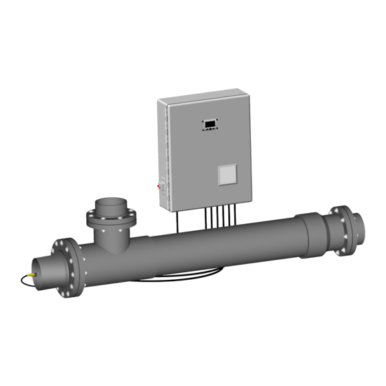
SECTION FIVE SYSTEM SPECIFICATIONS WATER WATER TEMP. SENSOR PORT OUTLET PORT QUARTZ SLEEVE/ UV INTENSITY SENSOR PORT UV LAMP ACCESS PORTS WATER INLET PORT LAMP FIELD WATER DRAIN PORT SAFETY COVER REMOVABLE HEAD SECTION Above: Bioshield™ UV Disinfection System polymer UV vessel, outfitted with raised flanges (available in all vessel diameters). Electrical and Flow Specifications UV-C Max. -
Page 11: Water Flow Rates
SECTION SIX INSTALLATION Pre-Installation Inspection Purpose To familiarize the installer/operator with the Bioshield™ UV Disinfection System components, to assure proper delivery of all the system’s components and to inspect each component for shipping damages. Frequency To be con ducted prior to installation. Parts and Required Equipment •... -
Page 12: Uv Vessel Installation
UV Vessel Installation Purpose Proper installation of the UV Vessel achieves expected results and ensures safe operation. Frequency Required with new construction, retro-fit or replacement of outdated equipment. Parts and Required Equipment • Socket Wrenches • Adjustable Wrenches • Set of Slotted and Phillips Head Screwdrivers •... -
Page 13: Quartz Sleeve Installation
4. Models equipped with inlet/outlet raised flanges require mating pipe flanges (not included). Depending on port type ordered, further fabrication may be required by the installer. 5. Isolation Valves are necessary for vessel removal and chemical cleaning procedure. It is recommended to install the isolation valves in conjunction with a separate set of, matching size &... - Page 14 Carefully slide the quartz sleeve(s) into the Quartz Sleeve Faceplate’s “Quartz Sleeve Module” (QSM) allowing approximately 12” of the quartz sleeve to remain outside the UV vessel. With 12” of the quartz sleeve exposed outside the vessel, carefully place the Quartz Sleeve Rubber Gasket Seal onto the open-end of the quartz sleeve.
-
Page 15: Power Supply Installation
Power Supply Installation Purpose Power Supply Enclosure is part of the complete Bioshield™ UV Disinfection System. Frequency Required with new construction, retro-fit or replacement of outdated equipment. Parts and Required Equipment • Set of Slot and Phillips Head Screwdrivers • Adjustable Wrench •... -
Page 16: Temperature And Uv Intensity Sensor Installation
Note: This Run Confirm relay circuit is intended to be used as a status indicator only, and is NOT currently wired for a load bearing circuit. Please contact Pentair Commercial Aquatics prior to using this relay circuit as anything other than a status indicator. - Page 17 Temperature & UV Intensity Sensor Installation Purpose To instruct the operator how to properly install the Temperature and UV Intensity Sensors. Frequency Required with new installation or when servicing the unit during general maintenance. Parts and Required Equipment • Flare-Nut Wrenches •...
-
Page 18: Section 7: Mandatory Water Test
SECTION SEVEN MANDATORY WATER TEST Mandatory Water Test Purpose The Mandatory Water Test identifies a potential quartz sleeve assembly seal failure. During normal UV system operation, a quartz sleeve assembly failure can result in extensive damage to the UV lamp, quartz sleeve and ballast. Frequency The Mandatory Water Test must be performed after a quartz sleeve/retaining nut gasket inspection/replacement. -
Page 19: Section 8: Uv Lamp Installation
SECTION EIGHT UV LAMP INSTALLATION UV Lamp Installation Purpose To instruct the operator how to properly install the UV lamp(s). Frequency Lamp installation in new unit or lamp replacement change-out (after every 12,000 hours of continual operation). Parts and Required Equipment •... - Page 20 Note: Each Lamp cable (1) is equipped with a Water Tight Connector (2). This cable adapter is made up of three components: Nut (3), Rubber Gasket (4) and Male-Threaded Body (5). Loosen (not remove) the lamp Water Tight Connector nut (3) to release tension on the lamp cable allowing the cable to slide freely through the adapter.
-
Page 21: Lamp Field Safety Cover Installation
Installation of Lamp Field Safety Cover Purpose To instruct the operator how to properly install the Lamp Field Safety Cover. Frequency Required anytime the lamp field is accessed. Parts and Required Equipment • Lamp Field Safety Cover • Pliers • Personal Safety Equipment General risk due to electricity. -
Page 22: Section 9: Commissioning
SECTION NINE COMMISSIONING Start-Up Purpose This section contains the necessary steps required to prepare the Bioshield™ UV Disinfection System for proper operation. Frequency Required with new construction, retro-fit or replacement of outdated equipment. Parts and Required Equipment • Personal Safety Equipment General risk due to pressurized piping and UV Vessel! General risk due to electricity! Hydraulic shock (water hammer) may occur as a result of improper use of valve(s) or trapped air inside the vessel. -
Page 23: Section 10: Operation
SECTION TEN OPERATION Microprocessor Controller Power Supply Operation Operation The operation of the Bioshield™ UV Disinfection System may only be carried out by authorized personnel. The personnel responsible for the operation of this system must read and understand Section 10, Section 2 (Health & Safety Precautions), and strictly comply with all relevant rules for accident prevention and local health and safety regulations. -
Page 24: Microprocessor Control Descriptions
Microprocessor Control Descriptions Incoming AC Voltage Monitor The Incoming AC Voltage Monitor monitors the input voltage to the UV system. If the value goes outside the acceptable threshold an alarm will be activated. For 120 VAC the threshold parameter is 95 – 140 VAC, for 230 VAC the threshold parameter is 210 –... - Page 25 Operator Text Display The Microprocessor Controller Text Display is used to present information to the operator as well as serving as a command interface. The microprocessor performs various functions that include intercepting operator commands and updating displayed data. In addition, the software verifies voltage, lamp operation and saves current hours to EEPROM, etc. Function Keys Command initiation is performed using the “Function Keys”...
- Page 26 MAIN UV System Text Display The “MAIN UV System Text Display” will appear after initialization. On this screen you will see: Total System Operating Hours, Input Voltage, and UV Intensity. Total Hours may be reset and the UV scaling adjusted via the “SETUP” menu. High and Low Input Voltage (95 –...
- Page 27 Voltage Range Displays the Factory-set “Low - Hi” Voltage set-points as well as the actual input voltage (YYY/incoming AC voltage). The UV System will not operate properly if operated outside the Voltage set-point range. Damage may incur to ballasts and lamps if the UV System is operated outside of the Voltage set-point range.
- Page 28 SETUP Menu Text Display Options RESET Master Counter Resets the “Master” hour counter. Press the “Right” key to select “Yes”, then press the “Enter” key to complete the command. To exit without making an adjustment select “Left”, this will return you to the SETUP Menu Text Display. RESET Single Counter Resets individual lamp hours.
- Page 29 ALARM Menu Text Display The ALARM Menu Text Display uses a “blinking border” to better alert the operator from a distance. The following ALARM Messages appear on the Text Display. Below, a brief description accompanies each ALARM message. Upon reaching the ALARM Text Display, pressing the “Right” key will advance the operator through additional ALARM screens if more than one ALARM has been activated.
- Page 30 LAMP Failure Alarm Identifies that a lamp has failed. The failed lamp number is displayed on the screen. The failed lamp should be replaced within 24 hours or the alarm will reactivate. An investigation should be performed to reveal the cause (water-damage, ballast or lamp) of the failure.
-
Page 31: Section 11: Maintenance
SECTION ELEVEN MAINTENANCE Routine Inspection The following are required routine maintenance actions: A. Daily inspection of the Bioshield™ UV Disinfection System Power Supply Enclosure control panel to confirm that the unit is operating satisfactorily (lamp operation). B. Daily visual inspection of the UV vessel and piping for leaks. C. -
Page 32: Uv Lamp Recycling
This service is intended to provide our customers with disposal service in compliance with State and Federal standards. This service may be utilized by our customers who are environmentally responsible and legally required. Your Pentair Sales Representative can assist you with this service call 800-831- 7133. - Page 33 Parts and Equipment Required • Quartz Sleeve(s) • Quartz Sleeve Retaining Nut Gasket • Adjustable Wrench • Clean Cotton or Silicon Gloves • Personal Safety Equipment General risk due to pressurized piping and UV vessel! General risk due to electricity! Quartz Sleeves are fragile and potentially dangerous if broken.
-
Page 34: Quartz Sleeve Cleaning
Quartz Sleeve Cleaning Purpose To manually check and clean quartz sleeve(s). Frequency When required, at least once annually. Parts and Equipment Required • Cleaning Agent (dish detergent, acid cleaning agent based upon phosphoric acid (>25%) • Acid-Proof Bucket • Clean Cloth •... - Page 35 Frequency When necessary. Parts and Equipment Required • Cleaning Agent (dish detergent, acid cleaning agent based upon phosphoric acid (>25%) • Acid-Resistant Transfer Pump • Acid-Resistant Hose (used to transfer the cleaner from the container to the UV vessel) • Fittings to connect to vessel •...
-
Page 36: Uv Vessel Disassembly
UV Vessel Disassembly Purpose To disassemble the vessel for internal inspection. Frequency UV vessel disassembly is only required if a problem has taken place, such as, quartz sleeve breakage. It is recommended that the QSM (Quartz Sleeve Module) Faceplate only be removed if necessary. Parts and Equipment Required •... - Page 37 Important: To properly align the QSM Faceplate, set the #1 lamp position (as stamped on the faceplate, next to the quartz sleeve module) to the 3 O’ Clock position when looking at the QSM Faceplate. 10. With the QSM Faceplate loosely aligned, push the QSM Faceplate, with the rubber gasket, in place onto the vessel.
-
Page 38: Cooling Fan And Filter Mat Replacement/Cleaning
Cooling Fan Filter Mat Replacement/Cleaning Cooling Fan Filter Removal Purpose The Cooling Fan is equipped with a Filter Mat used to trap airborne particles and dust. This Filter Mat must be routinely inspected and if required, cleaned. A clogged Filter Mat reduces air circulation in and out of the enclosure, potentially allowing electrical hardware to over-heat. -
Page 39: Section 12: Replacement Parts
SECTION TWELVE REPLACEMENT PARTS Bioshield™ UV Disinfection Systems are available in two sizes. They are: CLP4-Series units using 130 watt amalgam lamps and CLP6-Series units using 320 watt amalgam lamps. Among these UV System styles, there are variations that include: vessel dimensions, port styles/sizes and controller/ monitor options. -
Page 40: Replacement Parts
Replacement Parts Quartz Sleeve Module Faceplate....See supplied assembly drawing that was shipped with the unit or Call w/ Serial Number QSM Faceplate Rubber Gasket....See supplied assembly drawing that was shipped with the unit or Call w/ Serial Number UV Sensor................................20214-PL Optional UV Sensor Extension Cable........................20214-EXTCABLE-PL Temperature Sensor.............................20217-PL Optional Temperature Sensor Extension Cable....................20217-EXTCABLE-PL... -
Page 41: Section 13: Troubleshooting
SECTION THIRTEEN TROUBLESHOOTING SITUATION INSPECT FOR: UV system will not function 1. No Input Voltage Available with the External ON/OFF 2. Temperature Sensor Cable Plug is Interrupted/Defective Switch in the “On” position 3. Input Voltage is lower than the Factory Set Threshold UV Lamp does not light 1. - Page 42 NOTES...
- Page 43 NOTES...
- Page 44 Pentair Water Pool and Spa, Inc. Those names and brands may be the trademarks or registered trademarks of those third parties.
Need help?
Do you have a question about the BIOSHIELD CLP41A6-XN and is the answer not in the manual?
Questions and answers