Table of Contents
Advertisement
Available languages
Available languages
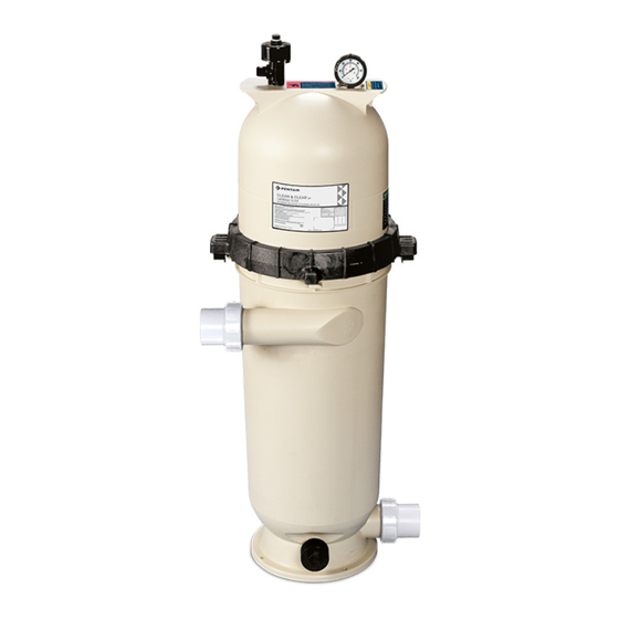
Clean & Clear
SECTION I.
FILTER INSTALLATION ............................................................................................... 1
SECTION II.
FILTER OPERATION ..................................................................................................... 2
SECTION III.
TROUBLESHOOTING................................................................................................... 6
SECTION IV.
TECHNICAL DATA ....................................................................................................... 7
A. Filter Pressure Loss Chart .......................................................................................... 7
C. Replacement Parts ..................................................................................................... 7
B. Flow Rate Table ......................................................................................................... 7
Before installing this product, read and follow all warning notices and instructions accompanying this
filter. Failure to follow safety warnings and instructions can result in severe injury, death, or property
damage. Call (800) 831-7133 for additional free copies of these instructions.
Attention Installer.
This manual contains important information about the installation, operation and safe
use of this product. This information should be given to the owner/operator of this
equipment.
SECTION I.
FILTER INSTALLATION
A. GENERAL INFORMATION
1. The filter should be mounted on a level concrete slab. Position the filter so that the instructions,
warnings and pressure gauge are visible to the operator. Also, position the filter so that the piping
connections, control valve and drain port are convenient and accessible
for servicing and winterizing.
2. Install electrical controls (e.g., on/off switches, timers control systems,
etc.) at least five (5) feet from the filter. This will allow you enough
room to stand clear of the filter during system start up.
3. Provide sufficient clearance around the filter to permit visual verification
that the clamp is properly installed, see Figure 1.
4. Provide sufficient space above the filter to remove the filter lid for
cleaning and servicing. This distance will vary with the model of filter
you are using. See Table 1, for the required vertical clearance.
Pentair Water Pool and Spa, Inc.
1620 Hawkins Ave., Sanford, NC 27330 • (800) 831-7133 • (919) 566-8000
10951 West Los Angeles Ave., Moorpark, CA 93021 • (800) 831-7133 • (805) 553-5000
Visit www.pentairpool.com or www.staritepool.com
Rev. D 6-26-09
Cartridge Filter Owners Manual
®
IMPORTANT SAFETY INSTRUCTIONS
READ AND FOLLOW ALL INSTRUCTIONS
SAVE THESE INSTRUCTIONS
Table of Contents
Important Notice
WARNING
1
Figure 1.
P/N 178556
Advertisement
Chapters
Table of Contents
Troubleshooting

Related Manuals for Pentair Pool Products CC50


Summary of Contents for Pentair Pool Products CC50
-
Page 1: Table Of Contents
This distance will vary with the model of filter you are using. See Table 1, for the required vertical clearance. Pentair Water Pool and Spa, Inc. 1620 Hawkins Ave., Sanford, NC 27330 • (800) 831-7133 • (919) 566-8000 10951 West Los Angeles Ave., Moorpark, CA 93021 •... -
Page 2: Filter Operation
WARNING Risk of electrical shock or electrocution. Position the filter and High Flow™ manual air relief valve to safely direct water drainage and purged air or water. Water discharged from an improperly positioned filter or valve can create an electrical hazard that can cause severe personal injury as well as damage property. 5. - Page 3 A. GENERAL INFORMATION 1. This filter operates under pressure. When the lock ring is installed properly and operated without air in the water system, this filter will operate in a safe manner. 2. The maximum working pressure of this filter is 50 psi. Never subject this filter to pressure in excess of this amount - even when conducting hydrostatic pressure tests.
- Page 4 WARNING THIS FILTER OPERATES UNDER HIGH PRESSURE. WHEN ANY PART OF THE CIRCULATING SYSTEM (e.g., LOCK RING, PUMP, FILTER, VALVES, ETC.) IS SERVICED, AIR CAN ENTER THE SYSTEM AND BECOME PRESSURIZED. PRESSURIZED AIR CAN CAUSE THE LID TO BE BLOWN OFF WHICH CAN RESULT IN SEVERE INJURY, DEATH, OR PROPERTY DAMAGE.
- Page 5 2. Open the filter High Flow™ manual air relief valve, (and the waste drain valve, or cap, if your system has one). NOTE Special care must be taken when cleaning cartridge element used in a swimming pool or spa using Baquacil ®...
-
Page 6: Troubleshooting
F. CLEANING THE HIGH FLOW™ MANUAL AIR RELIEF VALVE 1. Turn the pump off and shut off any automatic controls to ensure that the system is not inadvertently started during servicing. 2. OPEN THE HIGH FLOW™ MANUAL AIR RELIEF VALVE UNTIL IT SNAPS INTO THE FULL OPEN POSITION, THEN WAIT UNTIL ALL PRESSURE IS RELIEVED. -
Page 7: Technical Data
SECTION IV. TECHNICAL DATA A. Filter Pressure Loss Chart B. Flow Rate Table l a i l a i PRESSURE LOSS vs FLOW t r a d i r t r a d i r . t f (1) One GPM per sq. ft. shown, recommended flow rate for residential is .5 GPM per sq. ft. (2) Commercial flow rate is a maximum of .375 GPM per sq. - Page 8 Unless noted, names and brands of others that may be used in this document are not used to indicate an affiliation or endorsement between the proprietors of these names and brands and Pentair Water Pool and Spa, Inc. Those names and brands may be the trademarks or registered trademarks of those parties or others.
- Page 9 GLOBRITE C OLOR CHANGING ® UNDERWATER LED LIGHT FOR POOL AND SPA INSTALLATION USER’S GUIDE IMPORTANT SAFETY INSTRUCTIONS READ AND FOLLOW ALL INSTRUCTIONS SAVE THESE INSTRUCTIONS...
- Page 10 Technical Support Phone: (800) 831-7133 - Fax: (800) 284-4151 www.pentair.com Contents IMPORTANT WARNING AND SAFETY INSTRUCTIONS......... iii GloBrite Color Changing LED Pool Light Overview .......... 1 Operating GloBrite Color Lights Using a Wall Switch ........1 Operating GloBrite Color Lights Using an Automation Control System .... 1 Using and External Transformer for Multiple 12 VAC GloBrite Color Lights ..
-
Page 11: Important Warning And Safety Instructions
IMPORTANT WARNING AND SAFETY INSTRUCTIONS SERIOUS BODILY INJURY OR DEATH CAN RESULT IF THIS LIGHT IS NOT INSTALLED AND USED CORRECTLY. INSTALLERS, POOL OPERATORS AND POOL OWNERS MUST READ THESE WARNINGS AND ALL INSTRUCTIONS BEFORE USING THE POOL AND/OR SPA LIGHT. Most states and local codes regulate the construction, installation, and operation of public pools and spas, and the construction of residential pools and spas. - Page 12 POOL AND SPA FIXED LUMINARIES: Follow these guidelines when installing or replacing Pentair Aquatic Systems Pool and Spa fixed luminaries: FOR LIGHT OPERATION, ONLY USE A SAFETY ISOLATION TRANSFORMER. Note: Connect both wires to the corresponding circuit wires in the Junction...
-
Page 13: Globrite Color Changing Led Pool Light Overview
Maximum Wattage Using Multiple Color LED lights (with a 300 Watt Isolation Transformer) IMPORTANT! When using multiple 12 VAC Pentair LED pool and spa lights the total allowable light wattage is 300 Watts maximum. The individual light wattage is as follows: •... -
Page 14: Operating Globrite Color Lights Using A Wall Switch
For details about saving color effects while in “show” modes, see “Hold” and “Recall” feature on page 3. SAm Mode: Cycles through white, magenta, blue and green colors (emulates the Pentair SAm color changing light). ®... -
Page 15: Selecting A Globrite Light Color And Show Modes Or Fixed Color
Example: To select California Sunset Mode; turn the switch off and on six (6) successive times. During the off/on switching process, no illumination will occur, then a white light will momentarily illuminate. During the off/on switching process, before the selected color is displayed, no illumination will occur. This operating mode is normal during the switching process. -
Page 16: Globrite Light Fixture Installation (New Pool Construction Usa)
® GLOBRITE LIGHT FIXTURE INSTALLATION (NEW POOL CONSTRUCTION - USA) The following describes how to install the GloBrite Color Light fixture. BEFORE STARTING: The following information describes the tasks that must be completed by the electrician before the light fixture is installed. See Figure 1 on page 7. -
Page 17: Globrite Light Fixture Installation (New Pool Construction Canada)
® GLOBRITE LIGHT FIXTURE INSTALLATION (NEW POOL CONSTRUCTION - CANADA) Be sure the electrical system of your pool conforms with the following requirements of the Canadian Electrical Code (CE), and all local codes and ordinances. A licensed or certified electrician must install the electrical system to meet or exceed those requirements before the light and (fixture-housing) is installed. -
Page 18: Option 1: Light Niche Sleeve With Cone
® Installing GloBrite Light Sleeve and Niche in a Concrete/Gunite Pool - Option 1 and Option 2 (see page 7) Option 1: Niche Sleeve with Cone (Cone is used for applications where the niche is installed after the conduit has been connected to the 2” sleeve) Install Sleeve: Locate position on vertical pool or spa wall where light is to be installed. -
Page 19: Option 2: Conduit To Light Niche
Option 2: Install Conduit to Light Niche To install the conduit onto the GloBrite Color Light niche: ® Install Sleeve: Locate position on vertical pool or spa wall where light is to be installed. The top of the light lens must be a minimum of 10.2 cm (4 in) inches below normal water level. - Page 20 1.22 m (48 in) minimum To 12 VAC Transformer 10.2 cm (4 in) (20.3 cm (8 in) USA: 10.2 cm Canada: 600 mm max. (4 in) to top of to centerline of the Lens lens Ridgid Niche Sleeve 2.54 cm (1 in) (cut flush to wall before plastering) Conduit...
- Page 21 ® Installing GloBrite Color Light Niche in a Vinyl Pool To install the GloBrite color light niche in a vinyl liner pool: Drill a 7.62 cm (3 in) hole in the desired location for the light vinyl niche. From the inside of the pool, insert the vinyl niche through the 7.62 cm (3 in) hole.
- Page 22 ® INSTALLING THE GLOBRITE WHITE LIGHT ASSEMBLY (AFTER NICHE INSTALLATION) To install the GloBrite color light into the gunite, fiberglass or vinyl niche: Route the GloBrite light power cord through the front of the niche, to the location of the 12 VAC pool transformer or junction box. At the 12 VAC transformer or junction box, cut off any extra cord.
- Page 23 Place the light installation tool (P/N 620057) over the front of the light. Turn the tool and light clockwise (less than an .3175 cm (1/8th. turn), while pushing inward, until you feel the stop point. This indicates the light is properly seated, locked and the niche is completely sealed.
-
Page 24: Replacing The Globrite Light Assembly (In An Existing Pool Or Spa)
® REPLACING THE GLOBRITE LIGHT ASSEMBLY (IN AN EXISTING POOL OR SPA) Risk of Electrical Shock or Electrocution! This underwater light must be installed by a licensed or certified electrician or a qualified pool professional in accordance with the current National Electrical Code (NEC), NFPA 70 or the Canadian Electrical Code (CEC), CSA C22.1 and all applicable local codes and ordinances. - Page 25 IMPORTANT NOTICE: ® THE GLOBRITE LIGHT IS A NON-SERVICEABLE LIGHT. THE COMPLETE LIGHT ASSEMBLY MUST BE REPLACED. The following removal and installation instructions describe how to remove and install the GloBrite color light assembly. IMPORTANT NOTICE: THE GLOBRITE LED LIGHT IS A NON- SERVICEABLE LIGHT.
- Page 26 ® CONNECTING GLOBRITE LIGHTS TO ® ® EASYTOUCH OR INTELLITOUCH CONTROL SYSTEM LOAD CENTER TO AN AUXILIARY RELAY RISK OF ELECTRICAL SHOCK OR ELECTROCUTION Always disconnect AC power to EasyTouch and IntelliTouch control system load center at the circuit breaker before servicing, or removing the HIGH VOLTAGE FRONT PANEL.
- Page 27 AUXILIARY RELAYS EASYTOUCH 4 AUTOMATION CONTROL ® AUX 1 AUX 1 LOAD 1 LINE 1 LINE 1 CIRCUIT BREAKER GROUND NEUTRAL Note: Qty 6 to 17 GloBrite 12 VAC Lights require a 300 Watt transformer. 120V/12V LOAD 1 Step Down Black Black Transformer...
- Page 28 ® SETTING UP GLOBRITE WHITE LIGHTS WITH ® ® EASYTOUCH AND INTELLITOUCH CONTROL SYSTEM ® EasyTouch Control System The following describes how to setup the GloBrite Color Light from the EasyTouch control ® system indoor control panel or the EasyTouch control system wireless control panel. From the EasyTouch control panel you can control the light shows.
-
Page 29: Setting Up Globrite Color Lights With Easytouch/Intellitouch Control System
® IntelliTouch Control System The following describes how to setup the GloBrite Color Light from the IntelliTouch ® ® control system control panel. From the IntelliTouch control system control panel you can ® control the light shows. To access the GloBrite light screens, from the IntelliTouch indoor control panel or the MobileTouch Wireless Remote control panel. - Page 30 Operating and Selecting GloBrite (IntelliBrite Color Light) Color Modes From the “Modes” screen you can select various preset show color lighting effects, such as “American mode” and “Sunset mode,” and Pentair SAm Color Changing Light ® (an emulation of the SAm color scheme). Using the “Hold” and “Recall” feature you can also capture and save a unique color effect to recall at a later time.
-
Page 31: Troubleshooting
® ® Wiring GloBrite Color Lights to IntelliBrite Controller and 300 Watt Transformer The following diagram shows how to connect GloBrite color light to an IntelliBrite ® Controller using a 300 Watt transformer. Note: For GloBrite light operating instructions, see page 2. 300 Watt wire nut Transformer... -
Page 32: Globrite Color Lights Parts List And Replacement Kits
® GloBrite Color Lights Parts List and Replacement Kits GloBrite Lights Part No. Description 602053 GloBrite 12 VAC 30’ cord 602054 GloBrite 12 VAC 50’ cord 602055 GloBrite 12 VAC 100’ cord 602056 GloBrite 12 VAC 150’ cord GloBrite Bundles Part No. - Page 33 Notes GloBrite Color Changing LED Pool/Spa Light Installation and User’s Guide...
- Page 34 Notes...
- Page 35 Notes GloBrite Color Changing LED Pool/Spa Light Installation and User’s Guide...
- Page 36 Pentair Water Pool and Spa, Inc. Those names and brands may be the trademarks or registered trademarks of those third parties. Because we are continuously improving our products and services, Pentair reserves the right to change specifications without prior notice.
- Page 37 LÁMPARA LED SUMERGIBLE MULTICOLOR GLOBRITE ™ ™ PARA PISCINAS Y SPA GUÍA DE INSTALACIÓN Y DE USUARIO INSTRUCCIONES DE SEGURIDAD IMPORTANTES LEA Y SIGA TODAS LAS INSTRUCCIONES GUARDE ESTAS INSTRUCCIONES Guía de instalación y de usuario para lámpara LED multicolor GLOBRITE™ de piscina/spa...
- Page 38 Soporte técnico Teléfono: (800) 831-7133 - Fax: (800) 284-4151 Sitios web: www.pentair.com Contenido ADVERTENCIA IMPORTANTE E INSTRUCCIONES DE SEGURIDAD......i-ii Información general de la lámpara LED multicolor GloBrite para piscinas ...... 1 Controlar las lámparas de color GloBrite con un interruptor de pared ......1 Controlar las lámparas de color GloBrite con un sistema de control automático ....
- Page 39 INSTRUCCIONES IMPORTANTES DE ADVERTENCIA Y SEGURIDAD NO INSTALAR Y UTILIZAR ESTA LÁMPARA CORRECTAMENTE PUEDE PELIGRO CAUSAR LESIONES FÍSICAS O LA MUERTE. LOS INSTALADORES, OPERADORES Y PROPIETARIOS DE LA PISCINA PELIGRO DEBEN LEER ESTAS ADVERTENCIAS Y TODAS LAS INSTRUCCIONES ANTES DE USAR LA LÁMPARA DE PISCINA Y/O SPA. La mayoría de los códigos regionales y estatales regulan la construcción, la ADVERTENCIA instalación y la operación de spas y piscinas públicas, así...
- Page 40 No se requiere conexión adicional. LUMINARIAS FIJAS PARA PISCINAS Y SPA: Siga estas pautas al instalar o reemplazar luminarias fijas para piscinas y spas de Pentair Water Pool and Spa, Inc.: - PARA CONTROLAR LAS LÁMPARAS, UTILICE ÚNICAMENTE UN TRANSFORMADOR DE AISLAMIENTO DE SEGURIDAD.
-
Page 41: Información General De La Lámpara Led Multicolor Globrite Para Piscinas
(con un transformador de aislamiento de 300W) ¡IMPORTANTE! Cuando se utilizan varias lámparas LED blancas Pentair de 12 VCA en una piscina o en un spa, la potencia de consumo total permitida para las lámparas es 300W. La potencia de consumo individual por lámpara es la siguiente:... -
Page 42: Controlar Las Lámparas De Color Globrite Con Un Interruptor De Pared
“Hold” (Retener) y “Recall” (Recordar) en la página 3. SAm Mode (Modo Sam): Recorre los colores blanco, magenta, azul y verde (emula la luz de varios colores Pentair SAm ® Party Mode (Modo fiesta): Cambio de colores muy veloz que energiza y entusiasma. -
Page 43: Guardar Un Modo De Color O Color Fijo
Ejemplo: Para seleccionar el California Sunset Mode (modo Atardecer de California); alterne el interruptor entre encendido y apagado seis (6) veces consecutivas. Durante el proceso de alternación entre encendido/apagado, no habrá iluminación y luego se encenderá momentáneamente una luz blanca. Durante el proceso de alternación encendido/apagado antes ADVERTENCIA de que se visualice el color seleccionado, no se encenderá... -
Page 44: Instalar La Manga Y El Nicho De La Lámpara De Color Globrite (Una Vez Que Se Cumplen Los Requisitos Eléctricos)
® INSTALACIÓN DE LÁMPARA DE COLOR GLOBRITE (NUEVA CONSTRUCCIÓN DE PISCINA) A continuación se describe cómo instalar la unidad de iluminación de color GloBrite. ANTES DE COMENZAR: La siguiente información describe las tareas que el electricista debe realizar antes de instalar la unidad de iluminación. Vea la Figura 1 de la página 7. - Page 45 Instalar la manga y el nicho para lámparas de color GloBrite® en una piscina de cemento/gunita: opción 1 y opción 2 (ver página 6) Opción 1: Manga de nicho con cono (el cono se utiliza para aplicaciones en las que se instala el nicho después de conectar el conducto a la manga de 2") Instale la manga: Ubique la posición vertical en la piscina o el spa donde se instalará...
- Page 46 Opción 2: Instale el conducto en el nicho de la lámpara Para instalar el conducto en el nicho para lámparas de color GloBrite®: Instale la manga: Ubique la posición vertical en la piscina o el spa donde se instalará la lámpara. La parte superior del lente de la lámpara debe encontrarse como mínimo a 10,2 cm (4") debajo del nivel de agua normal.
- Page 47 Mínimo 1,22 m (48") Para el transformador de 12 VCA 10,2 cm (4") 20,3 cm (8") A 10,2 cm (4") de la parte superior del lente Manga del nicho Conducto Ridgid (cortar a nivel de la de 2,54 cm (1") pared antes de enyesar) Manga del nicho: caño de 5,08 cm (2") de PVC de 35,1 cm (15") de longitud...
- Page 48 Instalar el nicho para lámparas de color GloBrite® en una piscina de vinilo Para instalar el nicho para lámparas de color GloBrite en una piscina con recubrimiento de vinilo: Perfore un agujero de 7,62 cm (3") en el lugar deseado para el nicho de vinilo de la lámpara.
-
Page 49: Instalar El Módulo De Lámpara De Color Globrite (Después De La Instalación Del Nicho)
® INSTALAR LA LÁMPARA DE COLOR GLOBRITE (DESPUÉS DE LA INSTALACIÓN DEL NICHO) Para instalar la lámpara de color GloBrite® en el nicho de gunita, fibra de vidrio o vinilo: Extienda el cable eléctrico de la lámpara GloBrite por el frente del nicho hacia la ubicación del transformador de 12 VCA de la piscina o la caja de conexiones. - Page 50 Coloque la herramienta de instalación de la lámpara (P/N 620057) sobre el frente de la lámpara. Gire la herramienta y la lámpara en el sentido de las manecillas del reloj (menos de 0,3175 cm [1/8 de giro]), mientras empuja hacia adentro, hasta que sienta el punto en que se detiene.
- Page 51 ® REEMPLAZAR LÁMPARAS DE COLOR GLOBRITE (EN UNA PISCINA O UN SPA EXISTENTE) ¡Riesgo de descargas eléctricas o de electrocución! PELIGRO Esta lámpara sumergible debe instalarla un electricista certificado o con licencia, o en todo caso, un equipo profesional calificado de mantenimiento de conformidad con el Código Eléctrico Nacional (NEC) actual, NFPA 70 o con el Código Eléctrico Canadiense (CEC), CSA C22.1 y deben respetarse todos los códigos y las ordenanzas regionales...
-
Page 52: Reemplazar El Módulo De Lámpara De Color Globrite (Una Vez Que Se Cumplen Los Requisitos Eléctricos)
® REEMPLAZAR LA LÁMPARA DE COLOR GLOBRITE (UNA VEZ QUE SE CUMPLEN LOS REQUISITOS ELÉCTRICOS) Las instrucciones de desmontaje e instalación a continuación describen cómo desmontar e instalar el ensamblaje de lámparas de color GloBrite. NOTA IMPORTANTE: LA LÁMPARA DE COLOR GLOBRITE NO PUEDE RECIBIR MANTENIMIENTO. - Page 53 ® CONECTAR LÁMPARAS DE COLOR GLOBRITE AL CENTRO ® DE CARGA DEL SISTEMA DE CONTROL EASYTOUCH ® INTELLITOUCH A UN RELÉ AUXILIAR ¡P E L I G R O! PELIGRO RIESGO DE CHOQUE ELÉCTRICO O ELECTROCUCIÓN Siempre desconecte desde el disyuntor la alimentación AC del centro de carga del sistema de control EasyTouch e IntelliTouch antes de realizar tareas de mantenimiento o retirar el PANEL DELANTERO DE ALTO VOLTAJE.
- Page 54 RELÉS AUXILIARES EASYTOUCH 4 AUTOMATION CONTROL ® AUX 1 AUX 1 CARGA 1 LÍNEA 1 LÍNEA 1 INTERRUPTOR AUTOMÁTICO CONEX. A TIERRA NEUTRAL Transformador CARGA 1 reductor de Negro 120V/12V Negro Neutral (100W o 300W) CAJA Blanco (consulte la TERMINAL Blanco página 1 para Conex.
-
Page 55: Configurar Las Lámparas De Color Globrite Con El Sistema De Control Easytouch/ Intellitouch
CONFIGURAR LAS LÁMPARAS DE COLOR GLOBRITE® CON ® ® EL SISTEMA DE CONTROL EASYTOUCH E INTELLITOUCH Sistema de control EasyTouch ® A continuación se describe cómo configurar la lámpara de color GloBrite® desde el panel de control interno del sistema de control EasyTouch ®... - Page 56 ® Sistema de control IntelliTouch A continuación se describe cómo configurar las lámparas de color GloBrite® desde el panel ® de control del sistema de control IntelliTouch . Desde el panel de control del sistema de control ® IntelliTouch puede controlar los espectáculos. Acceder a las pantallas de la lámpara GloBrite, desde ®...
- Page 57 “American mode” (“Modo americano”) y el “Sunset mode” (“Modo ® atardecer”), así como la luz multicolor Pentair SAm (que emula el esquema de colores SAm). Al utilizar la función “Hold” (“Retener”) y “Recall” (“Recordar”), también puede capturar y guardar un efecto inigualable de colores para repetirlo en otro momento.
-
Page 58: Conectar Las Lámparas De Color Globrite Al Controlador Intellibrite Y Al Transformador De 300W
Conectar las lámparas de color GloBrite® al Controlador IntelliBrite y al transformador de 300 watts El siguiente diagrama indica cómo conectar la lámpara de color GloBrite® a un Controlador IntelliBrite con un transformador de 300 watts. Nota: Para leer las instrucciones operativas de la lámpara GloBrite, consulte la página 3. - Page 59 Lista de piezas y kits de reemplazo de las lámparas de color GloBrite® Lámparas GloBrite N. ° de Pieza Descripción 602053 Cable 12 VCA de 30' GloBrite 602054 Cable 12 VCA de 50' GloBrite 602055 Cable 12 VCA de 100' GloBrite 602056 Cable 12 VCA de 150' GloBrite Paquetes GloBrite...
- Page 60 ® ® son marcas comerciales y/o marcas registradas de Pentair Water Pool and Spa, Inc. y/o sus empresas afiliadas en Estados Unidos y/u otros países. A menos que se indique expresamente, los nombres comerciales y marcas de terceros que puedan haber sido utilizados en este documento no indican una asociación o respaldo entre los propietarios de estos nombres comerciales y marcas y Pentair Water...
- Page 61 LUMIÈRE DEL AQUATIQUE À COULEUR CHANGEANTE GLOBRITE ® POUR PISCINE ET SPA GUIDE D’INSTALLATION ET DE L’UTILISATEUR CONSIGNES DE SÉCURITÉ IMPORTANTES LISEZ ET RESPECTEZ TOUTES LES INSTRUCTIONS CONSERVEZ CES DIRECTIVES Manuel d'installation et de l'utilisateur pour la Lumière DEL à couleur changeante pour piscine et spa GLOBRITE...
- Page 62 Soutien technique Téléphone : 1-800-831-7133 – Télécopieur : 1-800-284-4151 Sites Web : www.pentair.com Contenu CONSIGNES DE SÉCURITÉ IMPORTANTES..............i-ii Aperçu de la lumière DEL à couleur changeante pour piscine GloBrite ......1 Utilisation des lumières colorées GloBrite avec un interrupteur mural ......1 Utilisation des lumières colorées GloBrite avec un système de contrôle automatisé...
- Page 63 AVERTISSEMENTS IMPORTANTS ET CONSIGNES DE SÉCURITÉ LE NON-RESPECT DE CES CONSIGNES D’INSTALLATION ET D’UTILISA- TION PEUT ENTRAÎNER DES BLESSURES GRAVES OU LA MORT. LES INSTALLATEURS, LES EXPLOITANTS ET LES PROPRIÉTAIRES DE PISCINE DOIVENT LIRE CES AVERTISSEMENTS ET TOUTES LES CONSIGNES AVANT D’UTILISER LA LUMIÈRE POUR PISCINE ET SPA. La plupart des codes fédéraux, provinciaux, territoriaux et locaux réglementent AVERTISSEMENT le secteur de la construction, de l’installation et du fonctionnement des piscines...
- Page 64 Aucune liaison supplémentaire n’est requise. LUMINAIRES FIXES POUR PISCINES ET SPAS : Suivez les instructions ci-dessous lors de l’installation ou du remplacement des luminaires fixes Pentair pour systèmes aquatiques de piscine ou de spa : - POUR L’UTILISATION DE LA LUMIÈRE, UTILISER UNIQUEMENT UN TRANSFORMATEUR D’ISOLATION DE SÛRETÉ.
-
Page 65: Aperçu De La Lumière Del À Couleur Changeante Pour Piscine Globrite
Puissance maximale pour plusieurs lumières DEL colorées GloBrite (avec transformateur d’isolation de 300 Watts) IMPORTANT! Lorsque plusieurs lumières DEL blanches 12 VCA Pentair pour piscine et spa sont utilisées, la puissance maximale autorisée est de 300 Watts. La puissance individuelle pour les lumières est la suivante :... -
Page 66: Utilisation Des Lumières Colorées Globrite Avec Un Interrupteur Mural
« Mémoriser » et « Rappel » à la page 3. Mode SAm : Alterne entre le blanc, le magenta, le bleu et le vert (imite la lumière à couleur changeante Pentair SAm ® Mode Fête : Changements de couleur rapides pour une ambiance amusante et remplie d’énergie. -
Page 67: Enregistrement D'un Mode De Couleur Ou D'une Couleur Fixe
Exemple : Pour sélectionner le mode Coucher de soleil californien, éteindre et allumer l’interrupteur six (6) fois de suite. Durant la commutation, il n’y aura aucun éclairage; ensuite, une lumière blanche s’allumera temporairement. Durant l’allumage ou l’extinction, avant que la couleur AVERTISSEMENT sélectionnée ne s’affiche, il n’y aura aucun éclairage. -
Page 68: Installation Du Dispositif De Lumière Colorée Globrite (Piscine Nouvellement Construite)
INSTALLATION DU DISPOSITIF DE LUMIÈRE COLORÉE GLOBRITE® (PISCINE NOUVELLEMENT CONSTRUITE) Ce qui suit décrit l’installation du dispositif de lumière colorée GloBrite®. AVANT DE COMMENCER : Les informations qui suivent décrivent les tâches à com- pléter par l’électricien avant l’installation du dispositif de lumière. Voir l’Illustration 1 à... -
Page 69: Installation Du Manchon Et De La Niche De La Lumière Colorée Globrite Pour Une Piscine De Ciment Ou De Gunite
Installation du manchon et de la niche de la lumière colorée GloBrite® pour une piscine de ciment/gunite – Option 1 et Option 2 (voir pages 6 et 7) Option 1 : Manchon de la niche avec cône (le cône est utilisé lorsque la niche est installée après le branchement du conduit au manchon de 2 po) Installer le manchon : Déterminer la position sur la paroi verticale de la piscine ou du spa où... -
Page 70: Option 2 : Conduit Vers La Niche De La Lumière
Option 2 : Installer le conduit vers la niche de la lumière Pour installer le conduit sur la niche de la lumière colorée GloBrite® : Installer le manchon : Déterminer la position sur la paroi verticale de la piscine ou du spa où... -
Page 71: Installation De La Lumière Colorée Globrite Pour Une Piscine De Fibre De Verre
1,22 m (48 po) minimum Vers transformateur 12 VCA 10,2 cm (4 po) 20,3 cm (8 po) 10,2 cm (4 po) jusqu’au-dessus de la lentille Manchon de la niche Conduit rigide de (couper pour affleurer la 2,54 cm (1 po) paroi avant le plâtrage) Manchon de la niche : Tuyau de PVC de 5,08 cm (2 po) et 35,1 cm... -
Page 72: Installation De La Lumière Colorée Globrite Pour Une Piscine De Vinyle
Installation de la niche de la lumière colorée GloBrite® pour une piscine de vinyle Pour installer la niche de la lumière colorée GloBrite® avec une piscine au revêtement de vinyle : Percer un trou de 7,62 cm (3 po) à l’endroit voulu pour la niche de vinyle de la lumière. De l’intérieur de la piscine, insérer la niche dans l’ouverture de 7,62 cm (3 po). -
Page 73: Installation Du Dispositif De Lumière Colorée Globrite (Après Installation De La Niche)
INSTALLATION DU DISPOSITIF DE LUMIÈRE COLORÉE GLOBRITE® (APRÈS L’INSTALLATION DE LA NICHE) Pour installer la lumière colorée GloBrite® dans une niche de gunite, de fibre de verre ou de vinyle : Diriger le cordon d’alimentation de la lumière GloBrite à travers l’avant de la niche, jusqu’à... - Page 74 Placer l’outil d’installation de la lumière (N/P 620057) sur le devant de la lumière. Tourner l’outil et la lumière en sens horaire (moins de 0,3175 cm [⅛ de tour]), tout en poussant vers l’intérieur, jusqu’à ce que l’outil ne tourne plus. Ceci indique que la lumière est bien ancrée et verrouillée et que la niche est complètement scellée.
-
Page 75: Remplacement Du Dispositif De Lumière Colorée Globrite (Pour Une Piscine Ou Un Spa Existant)
REMPLACEMENT DU DISPOSITIF DE LUMIÈRE COLORÉE GLOBRITE® (DANS UNE PISCINE OU UN SPA EXISTANT) Risque de décharge électrique ou d’électrocution! Cette lumière aquatique doit être installée par un électricien dûment certifié ou autorisé ou un professionnel en réparation de piscine qualifié conformément au Code national de l’électricité... -
Page 76: Remplacement Du Dispositif De Lumière Colorée Globrite (Lorsque Les Exigences Électriques Sont Respectées)
REMPLACEMENT DU DISPOSITIF DE LUMIÈRE COLORÉE GLOBRITE® (LORSQUE LES EXIGENCES ÉLECTRIQUES RESPECTÉES) Les instructions d’installation et de désinstallation qui suivent décrivent comment installer ou retirer le dispositif de lumière colorée GloBrite®. AVIS IMPORTANT : LA LUMIÈRE COLORÉE GLOBRITE NE PEUT PAS ÊTRE RÉPARÉE. -
Page 77: Easytouch/Intellitouch
® BRANCHEMENT DES LUMIÈRES COLORÉES GLOBRITE CENTRE D’ALIMENTATION DES SYSTÈMES DE CONTRÔLE ® ® EASYTOUCH OU INTELLITOUCH ET À UN RELAIS AUXILIAIRE D A N G E R ! RISQUE DE DÉCHARGE ÉLECTRIQUE OU D’ÉLECTROCUTION Toujours couper l’alimentation CA vers le centre d’alimentation des systèmes de contrôle EasyTouch et IntelliTouch au disjoncteur avant l’entretien ou le retrait du PANNEAU AVANT «... - Page 78 RELAIS AUXILIAIRES EASYTOUCH 4 AUTOMATION CONTROL ® AUX 1 AUX 1 CHARGE 1 LIGNE 1 LIGNE 1 DISJONCTEUR MISE À LA TERRE NEUTRE Transformateur CHARGE 1 abaisseur Noir Noir 120 V/12 V NEUTRE BOÎTE DE (100 W ou 300 W) Blanc JONCTION (voir page 1 pour...
-
Page 79: Configuration Des Lumières Colorées Globrite Avec Les Systèmes De Contrôle Easytouch/Intellitouch
CONFIGURATION DES LUMIÈRES COLORÉES GLOBRITE® AVEC LES ® ® SYSTÈMES DE CONTRÔLE EASYTOUCH ET INTELLITOUCH ® Système de contrôle EasyTouch Ce qui suit décrit comment configurer la lumière colorée GloBrite® à partir du panneau de commande ® intérieur ou du panneau de commande sans fil du système de contrôle EasyTouch . - Page 80 ® Système de contrôle IntelliTouch Ce qui suit décrit la configuration de la lumière colorée GloBrite® à partir du panneau de commande ® du système de contrôle IntelliTouch . Vous pouvez contrôler les spectacles de lumières à partir du ® panneau de commande du système de contrôle IntelliTouch .
- Page 81 À partir de l’écran « Modes », vous pouvez sélectionner différents effets de lumière colorée prédéfinis, comme le mode « Américain » et le mode « Coucher de soleil californien », ainsi que les lumières à couleur changeante Pentair SAm ®...
-
Page 82: Dépannage
Raccordement des lumières colorées GloBrite® au système de contrôle IntelliBrite et au transformateur 300 Watts Le schéma suivant montre comment brancher la lumière colorée GloBrite® à un régulateur IntelliBrite à l’aide d’un transformateur de 300 Watts. Remarque : Pour consulter les directives d’utilisation de la lumière GloBrite, voir page 3. - Page 83 Liste des pièces et trousses de remplacement pour lumières de couleur GloBrite® Lumières GloBrite de pièce Description 602053 Cordon de 30 pi 12 VCA GloBrite 602054 Cordon de 50 pi 12 VCA GloBrite 602055 Cordon de 100 pi 12 VCA GloBrite 602056 Cordon de 150 pi 12 VCA GloBrite Ensembles GloBrite...
- Page 84 ® ® sont des marques de commerce ou des marques déposées de Pentair Water Pool and Spa, Inc. ou de ses sociétés affiliées aux États-Unis ou dans d’autres pays. Sauf indication expressément contraire, les noms et les marques de tiers qui peuvent être utilisés dans le présent document ne sont pas utilisés pour indiquer une affiliation ou une approbation entre les propriétaires de ces marques et Pentair Water...
- Page 85 INTELLIFLO ® VARIABLE SPEED AND FLOW PUMP INSTALLATION AND USER’S GUIDE IMPORTANT SAFETY INSTRUCTIONS READ AND FOLLOW ALL INSTRUCTIONS SAVE THESE INSTRUCTIONS...
- Page 86 CUSTOMER SERVICE / TECHNICAL SUPPORT If you have questions about ordering Pentair Aquatic Systems replacement parts, and pool products, please contact: Customer Service and Technical Support, USA Sanford, North Carolina (8 A.M. to 4:30 P.M. ET) (8 A.M. to 4:30 P.M. — Eastern/Pacific Times)
-
Page 87: Important Pump Warning And Safety Instructions
230 VAC charge even when there is no This guide provides installation and operation instructions for this pump. power to the unit. Consult Pentair with any questions regarding this equipment. • The pump is not submersible. Attention Installer: This guide contains important information about the •... - Page 88 (D) Disabled submerged outlets, or (E) Suction outlets shall be reconfigured into return inlets. Warnings and safety instructions for Pentair Aquatic Systems pumps and other related products are available at: For Installation of Electrical Controls at Equipment Pad (ON/OFF http://www.pentairpool.com/pool-owner/safety-warnings/ or call...
-
Page 89: Pump Overview
VSF Variable Speed and Flow Pump ® can be programmed to run at a speed or a constant Most Pentair automation systems and IntelliComm ® flow rate over set time intervals for maximum operating Communication Centers can remotely control the efficiency and energy conservation for a variety of IntelliFlo VSF pump. -
Page 90: Installation
3. Plumbing on the suction side of the pump should be as location with better access. short as possible. For installation instructions refer to the Keypad 4. For most installations Pentair recommends installing Relocation Kit Installation Instructions provided with a valve on both the pump suction and return lines the kit. -
Page 91: Electrical Installation
POWER Drive Wiring LINE TERMINALS. Connection Pentair offers 2-Pole 20 Amp GFCI breakers (P/N PA220GF) which offer personnel protection while meeting 2008 to current NEC Standards for Pool 1/2” NPT Pumps. -
Page 92: Connecting To An Automation System
VSF Variable Speed and Flow Pump, are compatible with Pentair Automation Systems. An RS-485 communication cable is provided with the pump and will be used to connect the pump to a Pentair automation system. Refer to the automation system manual for further details on how to connect and use the system with your variable speed pump. -
Page 93: Operating The Pump
OPERATING THE PUMP NOTE: When setting up the IntelliFlo VSF Variable Speed and Flow Pump, the user must set the pump’s internal clock and ® establish an operation schedule by following the steps in this manual. Please refer to user’s guide sections: ‘Set Time’ (page 10) and ‘Set Programs 1-8 in Schedule Mode’... -
Page 94: Using The Operator Control Panel
Using the Operator Control Panel Use the operator control panel to start and stop the IntelliFlo ® Key Lockout Icon Variable Speed and Flow Pump, set, and change programs, and access pump features and settings. Controls and LEDs on Keypad 12:15p Button 1: Press to select Program 1 (750 RPM). -
Page 95: Stopping And Starting The Pump
Stopping and Starting the Pump Pump Operating Modes Starting the Pump The IntelliFlo VSF Variable Speed and Flow Pump can ® be programmed in three different modes: 1. Be sure the pump is powered on and the green Programs 1-4 can be programmed in all three modes. power LED is on. -
Page 96: Control Panel: Pump Menu Guide
Operator Control Panel: Pump Menu Guide MENU Press MENU button to access menus SETTINGS Date and Time Date Months (1-12) Days (1-31) (pages 10-13) Years (2010-2100 Plus) Time Hours (24hr Mode: 0-23) (12hr Mode: 1-12 AM & PM) Minutes (0-60) Hour Format AM/PM - Default: AM/PM 24 Hour... - Page 97 Operator Control Panel: Pump Menu Guide (cont.) MENU TREE CONTINUED FROM PREVIOUS PAGE Program 1 EXT CONTROL Type (Speed / Flow) Default: Speed Enabled - Default Set Speed or Flow - Default: 750 RPM (page 16) Stop Delay (0 min. to 10 min.) Default: 0 Minutes Pump Off Program 2 Type (Speed / Flow) Default: Speed...
-
Page 98: Pump Settings
MENU 7. Press the Up or Down arrows to edit the minimum speed setting from 450 to 1700 RPM. Pump Menu: Settings SETTINGS 8. Press Save to save. To cancel, press Back to exit edit mode without saving. Set Date and Time 9. -
Page 99: Set Flow Limit For Speed Program
Set Maximum System Pressure MENU The maximum pressure can be set using the drive, so that Pump Menu: Settings the pump does not exceed a set system pressure level SETTINGS when it is asked to do a high power job, or if the system Set Maximum Flow Rate (GPM) changes during normal operation. -
Page 100: Set Pressure Limit For Speed Program
Use this setting if your pump is connected via the RS-485 4. Use the Up or Down arrows to scroll to “Select COM port to a Pentair automation system. Language". Press Select. The default pump address is #1 and only needs to be 5. -
Page 101: Password Protection
9. Press the Left or Right arrows to move cursor and MENU press the Up or Down arrow to change the password number to desired setting. Pump Menu: Settings SETTINGS 10. Press Save to save. To cancel any changes, press Back to exit without saving. -
Page 102: Pump Operating Modes
Set Programs in Manual Mode MENU (Programs 1-4 Only) 1. Press Menu. Pump Menu: Programs 1-8 PROGRAM 1-8 2. Use Up or Down arrows to scroll to “Program 1-8”, Pump Operating Modes then press Select. This pump can be programmed in three different 3. -
Page 103: Set Programs 1-8 In Schedule Mode
MENU Pump Menu: Programs 1-8 PROGRAM 1-8 Set Programs 1-8 in Schedule Mode Programming Schedule for Constant Run Two programs cannot be programmed with the same In Schedule mode, Programs 1-8 can be programmed start and stop times. To run a program without stopping, to run a certain speed or flow at a certain time of day. -
Page 104: External Control
MENU Pump Menu: External EXT CONTROL Control External Control 6. Use the Up or Down arrow to scroll to "Set Type". Press Select. This function is for programming speeds or flows that 7. Use the Up or Down arrow to choose between will run when the IntelliComm Communication Center ®... -
Page 105: Features
7. Press Save to save the speed or flow setting. MENU 8. Press the Down arrow and press Select for “Time Pump Menu: Features Duration”. FEATURES 9. The cursor will highlight the minutes column. Use Time Out Up or Down arrows to change the time from 1 minute to 10 hours. -
Page 106: Priming
MENU Pump Menu: Priming PRIMING Priming Features Default: ENABLED Disabled/Enabled Allows IntelliFlo VSF Variable Speed and Flow Pump to automatically detect if pump ® if is primed for startup. The pump will speed up to 1800 RPM and pause for three (3) seconds - if there is enough water in the basket, the pump will go out of priming mode and run the commanded speed. -
Page 107: Setting Priming Features
MENU 14. Press the Down arrow to scroll to “Loss of Prime”. 15. The factory default is “Enabled“. To disable, press Pump Menu: Priming PRIMING Select to edit and use the Down arrow to scroll to "Disabled". Press Save. Setting Priming Features 16. - Page 108 MENU Pump Menu: Thermal Mode THERMAL MODE To Set Thermal Mode Speed/Flow and Pump The sensor for Thermal Mode is in the drive, on top of Temperature: the motor. This feature allows you to set a speed (450- 3450 RPM) or flow (20-140 GPM) that runs when the Note: Thermal Mode features are only accessible if IntelliFlo VSF Variable Speed and Flow Pump goes...
-
Page 109: Maintenance
MAINTENANCE DO NOT open the strainer pot if IntelliFlo VSF Variable Speed and Flow Pump fails to prime or if pump has been operating without ® water in the strainer pot. Pumps operated in these circumstances may experience a build up of vapor pressure and may contain scalding hot water. -
Page 110: Servicing
The Shaft Seal consists primarily of two parts, a rotating hands. Pentair recommends that safety gloves be worn when holding ceramic seal housed in the impeller and a stationary the impeller during disassembly and reassembly. -
Page 111: Pump Reassembly
Pump Reassembly 10. Reinstall the pump lid and plastic locking ring. See “Cleaning the Pump Strainer Basket” on page 21 1. When installing the replacement shaft seal, use for details silicone sealant on the metal portion before pressing 11. Reconnect the RS-485 communication cable to into the seal plate as shown. - Page 112 Drive Assembly Removal and KEYPAD Installation, (continued) ASSEMBLY KEYPAD Before installing this product, read and follow SCREWS (4X) all warning notices and instructions on page ii - iii. #10-24 X 1.75” PHILLIPS To install the drive assembly onto the motor HEAD SCREWS DRIVE TO MOTOR (3X) assembly:...
-
Page 113: Troubleshooting
Internal Error Indicates that the self-monitoring motor control software has encountered an error. Clear the alarm and restart the pump. If this alarm persists, contact Pentair Technical Service at 1-800-831-7133. Speed Limit (Warning) The pump has detected that it has met the maximum allowed speed set in the Min/Max menu. The pump will continue to run, but it will not achieve the desired speed. -
Page 114: Troubleshooting Chart
Troubleshooting Chart Problem Possible Cause Corrective Action Pump failure. Pump will not prime - Air leak in suction. Check suction piping and valve glands on any PRIME ERROR may be displayed. suction gate valves. Secure lid on pump strainer pot (For alert display and be sure lid gasket is in place. - Page 115 Problem Possible Cause Corrective Action Control panel LCD screen Loose drive wiring connection. Check the connection between the drive and keypad. displays sporadically or See image on page 3. The drive wiring connection flickers on/off. should be tight. Mechanical troubles and The pump motor is running but with loud noise.
-
Page 116: Replacement Parts
REPLACEMENT PARTS IntelliFlo VSF Variable Speed and Flow Pump Replacement Parts ® Item Almond Black Item Almond Black Description Description Part # Part # Part # Part # Clamp, Cam and Ramp 357199 357150 Drive Hardware Kit (Includes Drive 355685 Screws, Drive Gasket and Screw Caps) See Through Lid 357151... -
Page 117: Technical Data
TECHNICAL DATA Pump Dimensions Electrical Specifications Circuit Protection: Two-pole 20 AMP device at the Electrical Panel. Input: 230 VAC, 50/60 Hz, 3200 Watts Maximum, 1 phase Pump Performance Curves MAX SPEED - 3450 RPM OPERATING RANGE FOR FLOW CONTROL SPEED 4 - 3110 RPM SPEED 3 - 2350 RPM SPEED 2 - 1500 RPM SPEED 1 - 750 RPM... - Page 118 Operator Control Panel: Pump Menu Quick Reference Guide MENU Press MENU button to access menus SETTINGS Date and Time Date Months (1-12) Days (1-31) (pages 10-13) Years (2010-2100 Plus) Time Hours (24hr Mode: 0-23) (12hr Mode: 1-12 AM & PM) Minutes (0-60) Hour Format AM/PM - Default: AM/PM...
- Page 119 Operator Control Panel: Pump Menu Quick Reference Guide (cont.) MENU TREE CONTINUED FROM PREVIOUS PAGE Program 1 EXT CONTROL Type (Speed / Flow) Default: Speed Enabled - Default Set Speed or Flow - Default: 750 RPM (page 16) Stop Delay (0 min. to 10 min.) Default: 0 Minutes Pump Off Program 2 Type (Speed / Flow) Default: Speed...
- Page 120 States and/or other countries. Unless expressly noted, names and brands of third parties that may be used in this document are not used to indicate an affiliation or endorsement between the owners of these names and brands and Pentair Water Pool and Spa, Inc. Those names and brands may be the trademarks or registered trademarks of those third parties.
Need help?
Do you have a question about the Pool Products CC50 and is the answer not in the manual?
Questions and answers
how do i get the center core out of the existing cartridge filter to put in a new cartridge filter.