Table of Contents
Advertisement
Quick Links
Advertisement
Table of Contents

Subscribe to Our Youtube Channel
Related Manuals for EKOM DK50 3x4VR/M


Summary of Contents for EKOM DK50 3x4VR/M
- Page 1 DK50 3x4VR/M User manual...
- Page 3 COMPRESSOR DK50 3x4VR/M EKOM spol. s r. o. Priemyselná 5031/18 SK-921 01 Piešťany Slovak Republic tel.: +421 33 7967255 fax: +421 33 7967223 www.ekom.sk email: ekom@ekom.sk DATE OF LAST REVISION 06/2021 NP-DK50 3x4VR_M-AD-EN- 2_06-2021 112000493-0001...
- Page 4 CONTENTS ....................5...
-
Page 5: Table Of Contents
CONTENTS CONTENTS IMPORTANT INFORMATION ......................6 CONFORMITY WITH THE REQUIREMENTS OF THE EUROPEAN UNION ....6 INTENDED USE ......................6 CONTRAINDICATIONS AND SIDE-EFFECTS ..............6 SYMBOLS ........................6 NOTICE ........................... 7 STORAGE AND TRANSPORT CINDITIONS ..............9 PRODUCT DESCRIPTION ......................10 VARIANTS ........................ -
Page 6: Important Information
IMPORTANT INFORMATION IMPORTANT INFORMATION 1. CONFORMITY WITH THE REQUIREMENTS OF THE EUROPEAN UNION This product conforms to the requirements of the Regulation (EU) on medical devices (MDR 2017/745) and is safe for the intended use if all safety instructions are followed. 2. -
Page 7: Notice
IMPORTANT INFORMATION Fuse Compressed air inlet - dryer Compressed air outlet - dryer Control wire input Package handling label – fragile Package handling label – this side up Package handling label – keep dry Package handling label – temperature limits Package handling label –... - Page 8 IMPORTANT INFORMATION installation, new settings, changes, modifications and repairs are performed by the manufacturer or its representative, or a service provider authorized by the manufacturer.. the product is used pursuant to the user manual. The user manual corresponds to the configuration of the product and its compliance with applicable safety and technical standards at the time of its printing.
-
Page 9: Storage And Transport Cinditions
IMPORTANT INFORMATION Immediately disconnect the product from the mains in hazardous situations or when a technical malfunction occurs. During repairs and maintenance, ensure that: product is disconnected from the mains pressure is released from all lines Only the manufacturer, or a qualified specialist trained by the manufacturer may install, modify or upgrade the product itself. -
Page 10: Product Description
PRODUCT DESCRIPTION PRODUCT DESCRIPTION 7. VARIANTS The compressor is manufactured according to its intended application in the following variants: DK50 3x4VR/M Comprised of module: Compressor module Adsorption dryer module AD750E DK50 3x4VR/M 8. ACCESSORIES Accessories that are not included in the standard order must be ordered separately.;... -
Page 11: Product Function
PRODUCT DESCRIPTION Level of filtration Bypass Type Article number (µm) function * FS 40F 604014119-000 FS 40M 1+0.1 604014119-004 DK50 3x4VR FS 40S 1+0.01 604014119-024 FS 40AH 1+AC+HC(0.01) 604014119-005 *) These FS do not contain a filter bypass, which will ensure a continuous flow of air when replacing the filter element. - Page 12 PRODUCT DESCRIPTION Descriptions for figures 1 - 3 23 Circuit breaker Air pump 24 Contactor Air tank 25 Motor circuit breaker Non-return valve 26 Power supply 27 Logo DM8 Safety valve 28 Logo text display Pressure gauge 29 Pressure relief valve Drain valve 30 Common pump...
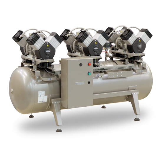
- Page 13 PRODUCT DESCRIPTION Fig. 1: DK50 3x4VR/M – Compressor with adsorption dryer 06/2021 NP-DK50 3x4VR_M-AD-EN-2_06-2021...
- Page 14 PRODUCT DESCRIPTION Fig. 2: Adsorption dryer NP-DK50 3x4VR_M-AD-EN-2_06-2021 06/2021...
- Page 15 PRODUCT DESCRIPTION Fig. 3: Switchboard 06/2021 NP-DK50 3x4VR_M-AD-EN-2_06-2021...
-
Page 16: Technical Data
Compressors are designed for operation in dry, ventilated and dust-free indoor rooms under the following climactic conditions: +5°C to +40°C Temperature Relative humidity max. 70% Working pressure 6 – 8 bar DK50 3x4VR/M Nominal voltage V, Hz 3x400, 50 Frequency Capacity at 6 bar (FAD) - l/min 20°C... - Page 17 TECHNICAL DATA Working pressure 6 – 8 bar DK50 3x4VR/M Nominal voltage V, Hz 3x400, 50 Frequency Capacity at 6 bar (FAD) - l/min 40°C 6.0 – 8.0 Working pressure Max. current 15.9 Main circuit protection device rating Main electrical feeder 5C x 1.5...
- Page 18 TECHNICAL DATA Dependence of compressor output on working pressure FAD correction of capacity for altitude Capacity given in the form of FAD („Free Air Delivery“) applies to the following conditions: 20°C Altitude 0 m.n.m. Temperature Atmospheric pressure 101325 Pa Relative humidity To calculate FAD compressor capacity in dependence on altitude, it is necessary to apply correction factor according to the following table: Altitude [m.n.m.]...
-
Page 19: Installation
INSTALLATION INSTALLATION Risk of incorrect installation. Only a qualified technician may install the compressor and place it into operation for the first time. Their duty is to train operating personnel on the use and maintenance of the equipment. An entry is made in the equipment installation record to certify installation and operator training. -
Page 20: Compressor Assembly
INSTALLATION Fig. 4: Equipment installation Air outlet Space conditions Temperature +5°C ÷ +40°C - Relative humidity 70% Recommended flow of cooling air: DK50 3x4VRT/M - 1850 m3/h. Applies for continuous operation and cooling air temperature of 20°C Cooling air inlet 11. - Page 21 INSTALLATION Fig. 5: Handling the compressor Remove the transport stabilisers from the air pumps – 6 mounts (Fig. 6). Prior to installation, ensure that the compressor is free of all transport packaging and stabilizers to avoid any risk of damage to the product. Remove all devices used to secure the aggregates once the compressor is installed and levelled at the site of final installation.
-
Page 22: Pneumatic Connection
INSTALLATION Install the dryer in its operating position (Fig. 7). Manipulation At least two persons are needed to handle the equipment. Integrated handles are installed on the lower brackets on the product. Each person must grasp the equipment with one hand on a handle and the other behind the dryer chamber when moving the equipment. - Page 23 INSTALLATION Fig. 8: Connecting the dryer to the compressor 06/2021 NP-DK50 3x4VR_M-AD-EN-2_06-2021...
- Page 24 INSTALLATION Risk of fire and electric shock. Ensure the power cord does not touch hot parts of the equipment or connecting hoses. AD dryer compressed air inlet Connect the compressed air outlet from the air tank to the dryer inlet (1). ...
-
Page 25: Electrical Connection
INSTALLATION Condensate outlet from dryer Connect a hose to the outlet (1) from the automatic condensate drain (2) to drain piping or to the provided collection vessel. A noise silencer is recommended when connecting directly to drain piping. Fig. 12: Codensate drain Risk of damage to pneumatic components. - Page 26 INSTALLATION 1. Connector Harting Fig. 14: Connecting the control signal Risk of fire and electric shock. Electrical cable must not be in contact with hot compressor components. Fig. 15: Power terminals L1, L2, L3 Risk of electric shock. It is necessary to follow all local electro technical regulations. The mains voltage and frequency must comply with the data stated on the device label.
- Page 27 INSTALLATION Use the RJ-45 connector on the switchboard door to connect a cable to the Ethernet network. (Fig. 16). Configuration of the IP address to connect to the local network: The default IP address of the BM module is: 192.168.0.3., TDE=192.168.0.2, sub- mask=255.255.255.0..
-
Page 28: Commissioning
INSTALLATION After logging in, the browser displays the first screen showing the system information for the controller itself: module generation, model, firmware (FW), IP address and activity status. Click on the “LOGO! BM” function in the browser to display the current virtual status of the BM text display screen. -
Page 29: Pneumatic Diagram
INSTALLATION 15. PNEUMATIC DIAGRAM DK50 3x4VR/M 06/2021 NP-DK50 3x4VR_M-AD-EN-2_06-2021... - Page 30 INSTALLATION Description to pneumatic diagram: Inlet filter 13 Cooler fan Compressor 14 Air tank 15 Condensate drain valve OR logic valve 16 Outlet valve Safety valve 17 Dryer solenoid valve 18 Vstupný filter komory Non-return valve Pressure valve 19 Adsorbent Condensate separator 20 Chamber outlet filter Condensate collection vessel...
-
Page 31: Operation
OPERATION OPERATION ONLY TRAINED PERSONNEL MAY OPERATE THE EQUIPMENT! Risk of electric shock. In case of emergency, disconnect the compressor from the mains (pull out the mains plug). Burn or fire hazard. Portions of the aggregate and compressed air components between the aggregate and the air cooler may be hot and reach hazardous temperatures during compressor operation that may harm materials or operating staff. -
Page 32: Switching On The Compressor
OPERATION 16. SWITCHING ON THE COMPRESSOR Turn the main switch into the “I” position on the compressor switchboard. A message appears on the display on the door of the switchboard, the dsplay shows: RUN MODE or STAND-BY MODE MOTORS : OFF or ON ... -
Page 33: Ad Dryer Operating Modes
OPERATION TOT.HOURS total time the compressor has been energised HOURS RUN: operating hours (motors TIME-TO-GO MN - time to the next maintenance / service work SERVICE COMP: number of 2,000 h maintenance checks performed on the compressor. - Page 34 OPERATION Display unit Home screen The home screen appears for 5 seconds when the main switch S1 on the dryer is switched to the “I” position „Adsorption dryer ADxx00Sis ON“ The display is backlit in white. The home screen is followed by the RUN MODE and STAND BY MODE screens based on the compressor control signal.
- Page 35 OPERATION Indication of an upcoming service interval 100 hours prior to the next service interval, the back lighting changes from white to orange and the display shows the message “SERVICE DUE IN XY HOURS”, where XY indicates the remaining number of hours until service is due.
- Page 36 OPERATION 17.2. Equipment operation Normal operating mode is shown when the equipment is operating and the functional and control buttons are used to browse through the following: Pressing F2: TOT.HOURS: total time the compressor has been energised HOURS RUN: operating hours (motors on) TIME-TO-GO MN - time to the next maintenance / service work SERVICE COMPR: number of 2,000 h...
- Page 37 OPERATION Alarm signals have a higher priority than maintenance/service interval signals. Low priority alarm conditions Expiry of defined maintenance / service interval. This alarm activates once the 2,000 hour maintenance / service interval expires. The display shows the following details: SERVICE ACCORDING TO THE INSTRUCTIONS FOR USE The display flashes orange.
-
Page 38: Switching Off The Compressor
OPERATION The compressor supplies compressed air to the central line through the functional air pumps. Fault - motor winding temperature fault The message on the display (ERROR) and blinking ALARM indicator indicate which of the aggregate motors has malfunctioned (open thermal overload switch (B11 - B13) inside the motor winding (M1 - M3). -
Page 39: Product Maintenance
PRODUCT MAINTENANCE PRODUCT MAINTENANCE 19. PRODUCT MAINTENANCE The operator should carry out device checks regularly in the intervals defined by applicable regulations. Test results must be recorded. The equipment has been designed and manufactured to keep maintenance to a minimum. The following work must be performed to preserve the proper and reliable operation of the compressor. - Page 40 PRODUCT MAINTENANCE 19.1. Maintenance intervals operator qualified technician NP-DK50 3x4VR_M-AD-EN-2_06-2021 06/2021...
- Page 41 PRODUCT MAINTENANCE Qualified technician 06/2021 NP-DK50 3x4VR_M-AD-EN-2_06-2021...
- Page 42 PRODUCT MAINTENANCE 19.2. Check of product operation Check aggregate condition – the aggregates should be operating normally without excessive vibration or noise. Troubleshoot any problem or call in service personnel if trouble is detected. Visually inspect fan operation – the fans must be operating when the aggregates are running. Troubleshoot any problem or call in service personnel if trouble is detected.
- Page 43 PRODUCT MAINTENANCE Check the power cord, conductors connected to the X1 terminal strip and the main switch to ensure they are undamaged. Inspect to ensure the connection terminals are properly supported to relieve tension. Check to ensure all threaded conductor terminals are tight (on motor circuit breakers Q1-3, main circuit breakers F1, contactors Q11-13, etc.).
- Page 44 PRODUCT MAINTENANCE ECS+▼ – „COUNTERS“ screen Information about counters, the number of times service has been performed and the number of times the solenoid valves have been activated MAINT – number of service operations VALVE – number of times the solenoid valves have been activated (the number displayed indicates the number of times the Inlet_A inlet valve into chamber A has been activated)
- Page 45 PRODUCT MAINTENANCE 19.6. Inlet filter replacement Inlet filter replacement: Pull out the rubber plug by hand (2). Remove the dirty intake filter (1). Insert a new filter and replace the rubber plug. Pre-filter replacement: Pull out the pre-filter by hand (3). ...
- Page 46 PRODUCT MAINTENANCE One air pump must be operating, shut off the remaining aggregates at the current protection device (25) in the switchboard. No air may leak through the check valves. Check for proper operation of the non-return valve (31) on the air tank by disconnecting the pressure hose from the valve Inspect the check valve once the air tank is pressurised and the compressor is off.
- Page 47 PRODUCT MAINTENANCE Venting compressed air poses an injury hazard Wearing hearing protection is recommended given the noise generated by the venting process. Shut off the compressed air source before venting pressure from the equipment. Venting pressure using the display screen Press ESC+▼...
- Page 48 PRODUCT MAINTENANCE 19.14. Replacement of the dryer´s internal filters Working with pressurised pneumatic components poses a risk of injury. Prior to any work, disconnect the equipment from the mains, shut off the compressor and vent all pressure in the equipment to zero. In normal operation, filter replacement must be performed in the upper part of the dryer at the defined interval.
- Page 49 PRODUCT MAINTENANCE 19.16. Replacement of the logic valve ball Turn off the compressor. Check the pressure in the dryer. If the dryer chambers are under pressure, proceed in accordance with Chapter 19.13. Unscrew the 4 screws (1) and remove the cover (2).
- Page 50 PRODUCT MAINTENANCE 19.19. Replacement of solenoid valves Risk of electric shock. Shut off the compressed air source, turn off the equipment and disconnect it from the mains before working on the equipment. Working with pressurised pneumatic components poses a risk of injury. Disconnect the equipment from the mains and vent the pressure in the equipment and the pneumatic system to zero before working on the equipment.
- Page 51 PRODUCT MAINTENANCE Fig. 27: Slenoid valve replacement Solenoid valve assembly Replacement solenoid valves are delivered as disassembled replacement parts. The new valve must be assembled before a solenoid valve is replaced. Mount the valve coil (4-5) onto the valve body (4-4) and secure with the nut (4-6). ...
- Page 52 PRODUCT MAINTENANCE compressed air circuit exceeds its pre-set value. The pressure relief valve closes as the pressure drops. The pressure in the compressed air circuit can only increase because of an increase in flow resistance in the compressed air lines or as a result of a dryer malfunction (e.g.
-
Page 53: Troubleshooting
TROUBLESHOOTING TROUBLESHOOTING Risk of electric shock. Before interfering with the equipment, first disconnect it from the mains (remove the power socket). Working with pressurised pneumatic components poses a risk of injury. Before interfering with the equipment, vent the air tank and the compressed air system to zero pressure. - Page 54 TROUBLESHOOTING Clean non-return valve, replace Non-return valve (SV) leakage seals, replace non-return valve Leak through solenoid valves once Clean the check valve - replace if regeneration is complete damaged Leak at pressure sensor and safety Test their function and clean, or valve replace if damaged Decrease air consumption...
-
Page 55: Repair Service
TROUBLESHOOTING Check the dryer connection to the mains and dryer connections, check Air leaking through relief valve at the dryer operation, check the dryer inlet dryer’s working pressure, and replace defective components. High working pressure from air Check the pressure setting on the source compressed air source Check the coil operation, replace if... -
Page 56: Annex
ANNEX ANNEX 23. INSTALLATION RECORD 1. Product: (model) 2. Serial number: DK50 3x4VR/M 3.1. User’s name: 3.2. Address of installation: 4. Equipment connected to the compressor: 5. Installation / Commissioning: 6. Contents of operator training: Product completeness check ** Description of the product and functions**... - Page 60 DK50 3x4VR/M EKOM spol. s r.o., Priemyselná 5031/18, 921 01 PIEŠŤANY, Slovak Republic tel.: +421 33 7967255, fax: +421 33 7967223 e-mail: ekom@ekom.sk, www.ekom.sk NP-DK50 3x4VR_M-AD-EN-2_06-2021 112000493-0001...
Need help?
Do you have a question about the DK50 3x4VR/M and is the answer not in the manual?
Questions and answers