Table of Contents
Advertisement
Quick Links
All rights reserved. Product description and product specifications are subject to change without notice.
For l a stest product information, please v i s it Acnodes' website at www.acnodes.com
14628 Central Ave. Chino, CA 91710
Tel: 909. 597. 7588
Fax: 909. 597. 1939
© C opyright 2015 Acnodes C orp.
Advertisement
Table of Contents

Subscribe to Our Youtube Channel
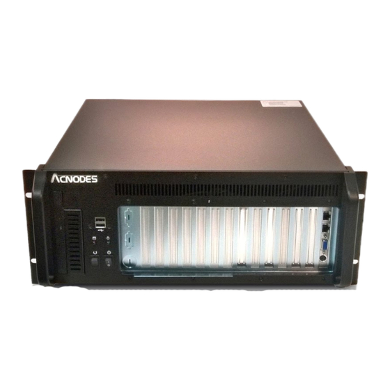
Summary of Contents for Acnodes RMC8416
- Page 1 All rights reserved. Product description and product specifications are subject to change without notice. For l a stest product information, please v i s it Acnodes’ website at www.acnodes.com 14628 Central Ave. Chino, CA 91710 Tel: 909. 597. 7588 Fax: 909. 597. 1939...
-
Page 2: Installation Steps
INSTALLATION STEPS Step 1: Align the retention screw holes on the side of the chas- sis with the retention screws in the handle. To install the RMC 8416 chassis, the following installation steps must be completed: Step 2: Insert 4 retention screws for each handle. Step 1: Unpack the chassis. - Page 3 STEP 3.2: HOLD-DOWN CLAMP REMOVAL Detach the hold-down clamp by removing the 2 screws located on each side of the chassis and lift the hold-down clamp off the chassis. Figure 5: Remove the 2 Hold-Down Clamp Retention Screws Figure 6: Lift the Hold-Down Clamp off the Hold-Down Clamp Securing Hook STEP 4: Install the Power Supply Unit (PSU) Once the top cover and hold-down clamp have been removed, the PSU must be installed.
-
Page 4: Step 5: Backplane Installation
15-inch touch panel PC STEP 5: BACKPLANE INSTALLATION The PSU is installed at the rear of the chassis. The PSU is secured to the chassis with an internal PSU securing The IEI backplanes listed below are compatible with the clamp and 4 retention screws from the rear of the chassis. RMC 8416 chassis. -
Page 5: Step 6: Cpu Card Installation
Step 3: Once the backplane is properly aligned with the Step 3: To secure the CPU card, reinsert the previously retention screw holes, insert retention screws in all the removed slot cover retention screw. retention screw holes in the backplane to secure the STEP 7: PCI/ISA EXPANSION CARD INSTALLATION backplane to the chassis. - Page 6 STEP 8.2: 3.5" DRIVE INSTALLATION INTO THE SIDE BRACKET The side bracket supports one 3.5" drive. If you want to install a 3.5" drive into the side bracket, please follow the steps below: Step 1: Place a 3.5" FDD drive into the bracket. Make sure the FDD PCB board is facing the surface of the bracket and the 4-pin power connector and the IDE/SATA interface connector are facing the rear of the bracket.
- Page 7 Figure 18: Install a 5.25" Disk Drive into the Main Drive Figure 16: Insert Four 3.5” Drive Retention Screws Bracket STEP 8.5: 5.25" DRIVE INSTALLATION IN THE MAIN STEP 8.6: REINSTALL THE DRIVE BRACKETS DRIVE BRACKET Once all the drives have been installed into the drive If you want to install a 5.25"...
- Page 8 Step 4: Reinsert the 2 previously removed side bracket The pin definitions for the USB cable are shown below retention screws into the top of the side bracket. STEP 9: CONNECT FRONT PANEL CABLES The RMC 8416 has LEDs, buttons and ports on the front bezel.
-
Page 9: Step 12: Cover Reinstallation
There are three 8 cm cooling fans inside the RMC 8416 chassis. To replace a fan, please follow the instructions below: Step 1: Loosen 2 thumbscrews for the fan that must be replaced. Figure 20: Hold-Down Clamp Retention Screw Holes in the Clip of the Side HDD bracket Step 3: Reinsert the 2 hold-down clamp retention screws. -
Page 10: Fan Filter Replacement
Figure 24: Remove the Fan Retention Screws Step 4: Replace the fan and secure a new fan to the fan bracket with the 4 previously removed retention screws. Step 5: Reinstall the fan bracket into the chassis and secure it to the chassis with the 2 previously loosened thumbscrews.


Need help?
Do you have a question about the RMC8416 and is the answer not in the manual?
Questions and answers