
Subscribe to Our Youtube Channel
Related Manuals for Philips FM-2


Summary of Contents for Philips FM-2
- Page 1 FM-2 (M2922A) Antepartum Fetal Monitor S E R V I C E G U I D E M2922-9000B Printed in Germany March 2002 Edition 1...
- Page 2 Notice Copyright © 2002 Philips Medizinsyteme Boeblingen GmbH. All rights reserved. Reproduction in whole or in part is prohibited without the prior written consent of the copyright holder. Philips Medizinsyteme Boeblingen GmbH Hewlett-Packard Strasse 2 71034 Boeblingen Germany Trademarks Microsoft ® is a U.S. registered trademark of Microsoft Corp.
- Page 3 On your monitor, this sign indicates that there is detailed information in this book which you must read before proceeding with your task Caution US law restricts this device to sale by, or on the order of, a physician.
-
Page 5: Table Of Contents
Contents 1. General Information ....... . 1 Introduction ............1 Who Should Read This Guide . - Page 6 FM-2 Power-On Self-Test ........
- Page 7 Removing the Speaker Housing ........41 Replacing the Speaker Housing .
- Page 8 M2922-64002 - Speaker Kit ........68 M2922-40003 - Battery Kit.
- Page 9 FM-2 Error Codes ........
- Page 11 List of Figures Figure 1 FM-2 Block Diagram of Operation ......7 Figure 2 Error Log .
-
Page 13: General Information
As this monitor is intended to be installed by the customer, refer to the Instructions for Use for details of how to install the monitor. The FM-2 Antepartum Fetal Monitor Service Guide supplements the maintenance and troubleshooting procedures carried out by the operator that are described in the Instructions for Use. -
Page 14: Who Should Read This Guide
Repair Strategy Who Should Read This Guide This guide is for any technical personnel servicing and repairing the FM-2 monitor (M2922A). You must: • understand English • be familiar with standard medical equipment installation procedures • be familiar with current conventional technical terms as used throughout... -
Page 15: Warnings, Cautions, And Notes
Warnings, Cautions, and Notes Warnings, Cautions, and Notes This guide uses three terms that are important for proper servicing of the monitor: Warning, Caution, and Note. Warning A warning calls your attention to an action or a possible situation that may result in injury or death to you or the patient. -
Page 16: Symbols And Definitions
Symbols and Definitions Symbols and Definitions Symbol Definition Symbol Definition Remote marker input Class II equipment symbol connector symbol on (double insulation) monitor Drip-proof equipment Type BF applied part classification on monitor symbol on monitor Power input symbol on Refer to accompanying power supply documents 220-240V~... -
Page 17: Packing For Shipment
Packing for Shipment Packing for Shipment General Instructions To ship the monitor for any reason, follow the instructions in this section. Pack the monitor carefully. Failure to follow the instructions in this section may result in loss or damage not covered by the warranty. If the original shipping carton is not available, use another suitable carton. -
Page 18: Overview Of The Device
Overview Of The Device Overview Of The Device General Description The device description included in this chapter focuses on the functional performance of the replaceable assemblies that may be identified as the probable cause of an apparent malfunction. Refer to the Instructions for Use for information about the operation of the monitor and of the Recorder. -
Page 19: Block Diagram Of Operation
Figure 1 illustrates the functional operation of the monitor, including the accessories and options. It incorporates features of the mechanical design, indicating the physical relationship of the assemblies and components. Figure 1 FM-2 Block Diagram of Operation Chapter 1 - General Information... -
Page 20: Mechanical Description
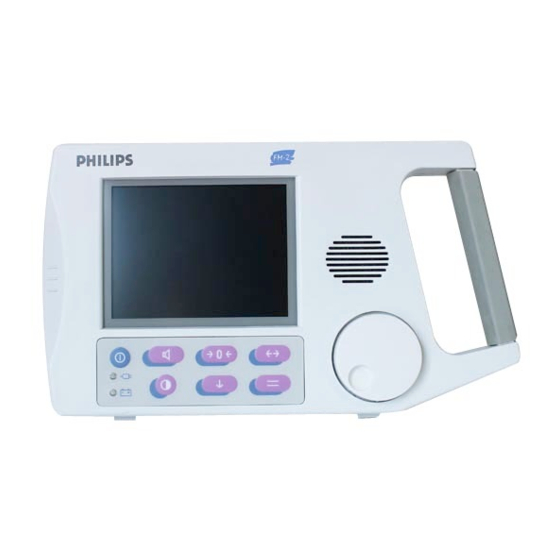
Mechanical Description Mechanical Description As indicated in Figure 1, except for the battery, speaker, interface board, and rear connector board, all functioning components of the monitor are installed as sub- assemblies of the case front-cover assembly. There are four sockets (event marker, Toco and two US) accessible on the left side panel. -
Page 21: Keypad And Navigation Wheel
Mechanical Description with the monitor, please see “Parallel I/O Communications Interface” on page 18. For further details of the pinouts and the cable specifications, see Chapter 2, “System Interfaces”. Keypad and Navigation Wheel There are seven front-panel switches, two LEDs, and one wheel push-button switch. -
Page 22: Measurements Channels
Measurements Channels Measurements Channels Ultrasound Channel The monitor has two ultrasound sockets, US 1 and US 2, located on the side panel of the monitor. Either one or two M1356A ultrasound transducers can be connected. The latter case allows twins monitoring. (Refer to the Instructions for Use for transducer specifications). -
Page 23: Routine Maintenance And Cleaning
Routine Maintenance and Cleaning Routine Maintenance and Cleaning For detailed instructions on how to clean the monitor and the monitoring accessories, see the Instructions for Use . For instructions on cleaning the Recorder, refer to the Instructions for Use . Chapter 1 - General Information... - Page 24 Routine Maintenance and Cleaning Chapter 1 - General Information...
-
Page 25: System Interfaces
System Interfaces Overview The monitor has the following system interfaces: • Serial I/O interface • Parallel I/O interface Note—The serial and parallel interfaces are not electrically isolated against each other. Serial I/O Communications Interface The RS-232 interface is totally isolated from the interface board through the use of high-speed optical isolators and isolated 5-volt power supply. -
Page 26: Supported Modems
Supported Modems The pinouts for the DB9 connector are shown in the following table. Table 1 Fully wired DB9 RS-232 Null-modem pinouts Connects Signal Details to pin 1 and 6 Data Terminal Ready Transmit data to external devices Receive data to external devices 1 and 6 DCD, DSR Data Carrier Detect, Data Set... -
Page 27: Multitech Systems Mt-5600Zdx
Supported Modems • a MultiTech Systems MT-5600ZDX desktop modem • a Nokia 6210GSM cellular phone modem (GSM type) MultiTech Systems MT-5600ZDX The monitor sends the following default modem initialization string: Modem Default ‘ATE0X4&K0\r’ Initialization String This is the first string sent by the monitor, and it is not customizable, nor is it obvious to the user. -
Page 28: Table 2 Multitech Mt-5600Zdx Initialization String Commands
Supported Modems Communications Menu Data Transfer Stopped Destination Printer/Recorder Set Modem Init String Paper Output Current Record Paper Speed (3 cm/min) Paper Style Modem Initialization Cancel Clear Number to Dial TOCO Return JANE DOE 194848 min. 16:34:12 2/14/2001 The components of the default initialization string are explained in the following table. -
Page 29: Nokia 6210Gsm
Supported Modems The commands above are only applicable to Rockwell/Conexant-based MultiTech Systems modems. At the time of printing, the MultiTech MT- 5600ZDX is the only desktop modem that has been validated for use with the monitor. The monitor may also work with other modems, but this has not been tested, and consequently no other modems are officially supported. -
Page 30: Parallel I/O Communications Interface
The parallel communications port is used to connect the FM-2 to the Recorder or to a standard PCL Level 3 printer. Supported printers that have been validated at the time of printing are: •... -
Page 31: Tests And Error Codes
In addition, the errors are written to the error log (see Table 3, “FM-2 Error Codes,” on page 23). Read the system error log to determine whether the fault lies in the hardware or firmware. -
Page 32: Checking The Battery
Do not use if there is any sign of damage. FM-2 Power-On Self-Test When the monitor is turned on, it automatically performs a diagnostic self-test. The self test continues during normal operation also. If the monitor fails its self test, it will display an error screen, and will discontinue all monitoring functions. -
Page 33: Performing The Power-On Self Test
5. If an error is detected, the monitor will display the error screen. 6. The error number is stored in the error log (see Table 3, “FM-2 Error Codes,” on page 23). If the Power-On Self Test fails, try to cycle power again. If it fails again, then exchange the monitor. -
Page 34: Performance Test For Transducers
Performance Test for Transducers Performance Test for Transducers This tests the signal path to and from the transducers. 1. Turn on the monitor and the recorder or printer. 2. Connect one or two US cables and the TOCO transducer. 3. Check that the display acknowledges the connected transducers in the appropriate frames. -
Page 35: Error Codes
Error Codes The error codes are primarily intended for diagnostic use at the factory. The errors, their explanation, and any service action required are shown in the following table. Table 3 FM-2 Error Codes Error Explanation Action Code Monitor’s memory has become corrupt... - Page 36 None: factory diagnostic infor- mation only File system wrapped memory Attempt to read a corrupt file Failed to create a file File corrupted - FM-2 viewer communication error Invalid Patient ID - FM-2 viewer communication error None: factory diagnostic infor- mation only...
-
Page 37: Power-Up Default Settings And The Service Menu
Power-up Default Settings and the Service Menu Introduction This section discusses use of the Power-up Defaults Menu to configure power- on default settings, and the Service Menu to obtain service-related information about the monitor. Power-up Defaults Settings These are parameters which can be changed by the user. The power-up defaults allow you to create a power-up default for many settings in the monitor. -
Page 38: Service Menu
Service Menu Table 4 Power-Up Default Settings Parameter Factory Default Saved Through Power Cycle Data transfer Yes (if real-time transfer) Disabled Data Transfer Destination Recorder/ Printer Recorder: Paper speed 3 cm/minute Recorder: Paper style Time format 12 hour Date “today” Date format mm/dd/yy Patient ID... -
Page 39: Table 5 Service Menu Entries
Service Menu Table 5 Service Menu Entries Menu Item Explanation View Error Log Displays the error log menu View A/D Values Displays the Analog-to-Digital (A/D) Menu System On-Time Elapsed system on-time (expressed in hours). System on-time is not reset to 0 after the battery is replaced, but is retained. -
Page 40: Error Log
Service Menu Error Log This screen displays the eight most recent error code types, logged by the monitor. After eight error code types have been logged, the oldest error code type will be deleted as new error code types are added. Adjacent to each error code will be an entry which is the number of occurrences of that error. -
Page 41: System A/D Values
Service Menu System A/D Values For the end user or service personnel, the system A/D values require no interpretation. The A/D screen displays the current value of each analog-to-digital (A/D) channel in volts. The A/D channels read DC voltages, for example, power supply voltages and battery voltage. - Page 42 Service Menu Chapter 4 - Power-up Default Settings and the Service Menu...
-
Page 43: Troubleshooting
Troubleshooting General This section provides a guide for qualified service personnel in locating the possible cause of an apparent malfunction of the monitor or its accessories. Use of built-in diagnostics, flow charts, and step-by-step procedures are provided as aids in the troubleshooting process. The chapter leads you to a probable field replaceable assembly or component. -
Page 44: Initial Trouble Diagnosis
General Initial Trouble Diagnosis The first step in diagnosing a possible malfunction is to duplicate, if possible, the symptoms of the reported malfunction. Thereafter, it is important to categorize the problem as either one of two types, as illustrated in Figure 4. They are: •... -
Page 45: Power Problem Diagnosis
Power Problem Diagnosis Power Problem Diagnosis Diagnostic Flow Chart The flow chart of Figure 5 shows a sequence of actions and decisions you can use after the initial diagnosis of a “total failure” as a power supply or display problem. Note—If the apparent “total failure”... -
Page 46: Diagnostic/Repair Actions
Power Problem Diagnosis Diagnostic/Repair Actions Reduce background room illumination. If only the back light fluorescent tube Examine Display or its high voltage driver has failed, the display may be faintly visible. Intensely Refer to page 50 for removal procedures. Refer to page 43. Replace Battery If the display is not at all visible, and there is total failure, exchange the monitor. -
Page 47: Monitoring Degradation Problems
Monitoring Degradation Problems Monitoring Degradation Problems Diagnostic Flow Chart Figure 6 illustrates a logical sequence of troubleshooting diagnostics when the monitor appears to be operative, but the displayed results are suspect for any number of reasons. The resulting diagnosis will result in replacing either the monitor or the transducers. -
Page 48: Diagnostic Repair Actions
Monitoring Degradation Problems Diagnostic Repair Actions Examine the display after an apparently successful power up sequence and self- Describe Degraded test. Performance Consider, first, the appearance of artifacts, gaps, or general quality of the display. Note the values being reported in the numerical frames (FHR(s)) and TOCO). Are they clearly unreasonable? Use a spare transducer that is free of defects and meets factory specifications. -
Page 49: Disassembly/Reassembly Guide
Disassembly/Reassembly Guide Warning Performance verification: do not place the monitor into operation after repair or maintenance has been performed, until all performance tests and safety tests listed in Chapter 8 of this service manual have been performed. Failure to perform all tests could result in erroneous monitor readings, or patient/operator injury. -
Page 50: How To Use This Chapter
How to Use this Chapter Caution Observe ESD (electrostatic discharge) precautions when working within the unit. Caution Important for disassembly! When disassembling the monitor, make sure that the battery leads are disconnected. Otherwise, it is likely that circuit damage will occur. The monitor can be disassembled down to all major component parts, including: •... -
Page 51: Tools Required
Tools Required All part numbers and exploded views of some assemblies are found in Chapter 7, “Spare Parts”. Tools Required Caution When reassembling, be sure to follow torque-limits instructions. Excessive torque may damage the plastic screw mountings or case. The following tools are required: •... -
Page 52: Closed Case Disassembly/Reassembly Procedures
Closed Case Disassembly/Reassembly Procedures Closed Case Disassembly/Reassembly Procedures This section describes the items that may be removed without disassembling the main case of the monitor. The speaker housing is attached to the back of the rear case. The speaker housing also acts as the battery cover. To gain access to the battery, first remove the speaker housing (see “Removing the Speaker Housing”... -
Page 53: Removing The Speaker Housing
Closed Case Disassembly/Reassembly Procedures Removing the Speaker Housing Step 1. Place the monitor on its front panel, being careful not to place the unit on any surface that will damage the display. Step 2. Using the Phillips-head screwdriver, unfasten the two screws securing the speaker housing. -
Page 54: Replacing The Speaker Housing
Closed Case Disassembly/Reassembly Procedures Replacing the Speaker Housing Step 1. Connect the speaker cables by pushing the spade terminals onto the speaker terminals in the speaker housing. Check that they are secure. The wires are not coded for polarity, as the polarity is uncritical. Speaker housing lugs Speaker... -
Page 55: Removing The Battery
Closed Case Disassembly/Reassembly Procedures Removing the Battery Step 1. Place the monitor upside down so that its top is resting on the work surface. In this position, the monitor leans back at a convenient angle that allows easy removal of the battery with the aid of gravity. Step 2. -
Page 56: Replacing The Battery
Closed Case Disassembly/Reassembly Procedures Replacing the Battery Step 1. Connect the battery cables to the replacement battery, paying careful attention to cable polarity. Connect the red cable to the positive terminal, marked in red. Connect the black cable to the negative terminal, marked in black. -
Page 57: Separation Of Front And Rear Case Assemblies
Separation of Front and Rear Case Assemblies Separation This section describes the procedures required to separate the front and rear case assemblies of the FM-2 monitor. Step 1. Remove the speaker housing (see “Removing the Speaker Housing” on page 41). -
Page 58: Reassembly
Separation of Front and Rear Case Assemblies Reassembly Step 1. Ensure that the cables for the speaker and the battery are correctly routed and accessible from the rear of the case for later connection. Step 2. Confirm that the patient connector PCB is firmly mated to the main PCB. -
Page 59: Front Case Disassembly/Reassembly Procedures
Front Case Disassembly/Reassembly Procedures Front Case Disassembly/Reassembly Procedures This section describes how to remove/replace items from the front case assembly. The front case assembly includes the replaceable molded front-case, the main PCB, the LCD assembly, the front-panel keypad and the navigation wheel. First separate the front and rear case assemblies as described in the section “Separation of Front and Rear Case Assemblies”... -
Page 60: Replacing The Navigation Wheel
Front Case Disassembly/Reassembly Procedures Replacing the Navigation Wheel Step 1. If the front case assembly has been disassembled, refit the LCD assembly (see “Replacing the LCD Assembly” on page 51) and the main circuit board (see“Replacing the Main PCB Assembly” on page 52) to the front case assembly. -
Page 61: Removing The Main Pcb Assembly From The Front Case Assembly
Front Case Disassembly/Reassembly Procedures Removing the Main PCB Assembly from the Front Case Assembly Step 1. Remove the navigation wheel (see “Removing the Navigation Wheel” on page 47). Step 2. Place the front case assembly with the bezel face down on the work surface. -
Page 62: Removing The Lcd Assembly
Front Case Disassembly/Reassembly Procedures Main PCB Rear case assembly assembly Front case assembly Removing the LCD Assembly Warning High voltage is generated by the LCD backlight driver. Do not operate the monitor with the covers open. The Display Kit (M2922-64004) comes with a replacement display window, which should be replaced when the LCD assembly is replaced. -
Page 63: Replacing The Lcd Assembly
Front Case Disassembly/Reassembly Procedures Step 3. Remove the display window by carefully prying up one corner and then peeling back. Front bezel assembly Display window Replacing the LCD Assembly Step 1. Fit the new display window with its gasket to the inside of the front bezel. -
Page 64: Replacing The Main Pcb Assembly
Front Case Disassembly/Reassembly Procedures Replacing the Main PCB Assembly Step 1. If the LCD assembly has been removed, first replace it. (See “Replacing the LCD Assembly” on page 51). Note—There are two notches on the main PCB, used for location purposes. - Page 65 Front Case Disassembly/Reassembly Procedures Notch & Notch guide & guide Main PCB screw fixing Backlight Keypad ribbon cable power & connector connector Step 7. Reconnect the backlight power supply connector to J4 on the main PCB. It is only possible to fit the connector one way round. Step 8.
-
Page 66: Removing The Keypad
Front Case Disassembly/Reassembly Procedures Removing the Keypad The keypad is attached to a recess in the front cover assembly by an integral double sided adhesive. Step 1. From the face of the front bezel, carefully pry up one corner of the keypad, then peel it away from the front cover. -
Page 67: Rear Case Disassembly Procedures
Rear Case Disassembly Procedures Rear Case Disassembly Procedures This section describes the items that may be removed/replaced on the rear case assembly of the monitor. First separate the front and rear assemblies as described in the section “Separation of Front and Rear Case Assemblies” on page 45. Removing the Rear Connector PCB and the Interface Board The interface PCB is connected at right angles to the rear connector PCB, and is separable from it. -
Page 68: Removing The Interface Pcb From The Rear Connector Pcb
Rear Case Disassembly Procedures Removing the Interface PCB from the Rear Connector PCB Step 1. Using a Phillips-head screwdriver, remove the two screws on the connector side of the connector PCB. Rear connector board Interface board Screws Step 2. Separate the two boards by disconnecting the two multi-pin connectors at J1 and J2 on the rear connector PCB. -
Page 69: Replacing The Rear Connector/Interface Pcb Assembly
Rear Case Disassembly Procedures Replacing the Rear Connector/Interface PCB Assembly Step 1. Place the rear connector/interface PCB assembly into the dedicated recess inside the rear case assembly. See that the RS-232, parallel and power supply connectors fit into their respective slots in the rear case. Step 2. -
Page 70: Removing The Handle
Rear Case Disassembly Procedures Removing the Handle Each end of the handle is a friction fit on a cross-shaped boss. Step 1. Use flat-bladed screwdriver to carefully pry one end of the handle. Step 2. When the end of the handle has begun to loosen from the boss, use the same technique to begin to pry up the other end. -
Page 71: Main Pcb Disassembly Procedures
Main PCB Disassembly Procedures Main PCB Disassembly Procedures This section describes the items that may be removed/replaced from the main PCB assembly of the monitor. The main PCB assembly is separable from the front case assembly. Step 1. First separate the front and rear assemblies as described in the section “Separation of Front and Rear Case Assemblies”... - Page 72 Main PCB Disassembly Procedures main Step 3. Use a Phillips-head screwdriver to remove the six screws that secure the side panel to the socket surrounds. Access to the screws is gained through the holes in the side connector PCB. Step 4. Remove the side panel from the side connector PCB. Chapter 6 - Disassembly/Reassembly Guide...
-
Page 73: Replacing The Side Panel/Side Connector Pcb
Main PCB Disassembly Procedures Replacing the Side Panel/Side Connector PCB Step 1. Place the side panel on the side connector PCB so that the sockets on the side connector PCB fit the holes in the side panel. Step 2. Using a Phillips-head screwdriver, fasten the side connector PCB to the side panel using the six screws. - Page 74 Main PCB Disassembly Procedures Chapter 6 - Disassembly/Reassembly Guide...
-
Page 75: Spare Parts
Spare Parts Introduction Spare parts, along with part numbers, are listed in the tables that follow. “Item No.” corresponds to the callout number in Figure 7 through Figure 11. The “Page Ref.” indicates the page number of the relevant disassembly procedures in Chapter 6. -
Page 76: Exchange Parts
Exchange Parts Exchange Parts Monitor (M2922A) Table 6 Exchange Assemblies - M2922A Exchange Part No. Description M2922-68000 Entire monitor M1355-69011 TOCO Transducer M1356-69011 US Transducer Recorder (M2925A) Table 7 Exchange Assemblies - M2925A Exchange Part Description M2925-68110 Recorder 100V, 120V M2925-68220 Recorder 220V, 240V Chapter 7 - Spare Parts... -
Page 77: Non-Exchange Parts
Small parts kit M2922-60511 Rear connector board 55, 57 M3921-61000 Power supply 100V - 120V M3921-61010 Power supply 220V - 240V M1380-61624 Serial interface cable to PC, OB TraceVue and FM-2 viewer 15249A Event marker Chapter 7 - Spare Parts... -
Page 78: Supplies And Accessories
Supplies and Accessories Supplies and Accessories Table 9 Supplies and Accessories - M2922A Part No. Description M1356-43203 Transducer knob adapters (3-pack) Breakdown of Spare Parts Kits by Component M2922-64003 - Small Parts Kit Table 10 M2922-64003 Small Parts Kit Component Description Quantity Screw, mach Phillips-head 4-40 X 3/16 Screw, tri-lob, Phillips-head 6 X 1/2... -
Page 79: M2922-64001 Housing Kit
Breakdown of Spare Parts Kits by Component M2922-64001 - Housing Kit Table 11 M2922-64001 Housing Kit Component Description Quantity Small Parts Kit Front case Louver cover plate Handle Rubber feet (cushions) Speaker retainer spring 1. For contents of the Small Parts Kit, refer to Table 10 on page 66. Chapter 7 - Spare Parts... -
Page 80: M2922-64002 - Speaker Kit
Breakdown of Spare Parts Kits by Component M2922-64002 - Speaker Kit Table 12 M2922-64002 Monitor Speaker Kit Component Description Quantity Small Parts Kit Speaker housing Bracket R/A 4-40 Speaker retainer Speaker Cable - speaker assembly Gasket - speaker Pad - battery, front/rear Label - rear Pad - battery, front/rear Pad - battery, right... -
Page 81: M3921-60406 - Knob (Navigation Wheel) Kit
Breakdown of Spare Parts Kits by Component M3921-60406 - Knob (Navigation Wheel) Kit Table 14 M2922-60406 Knob (Navigation Wheel) Kit Component Description Quantity Knob Ring retaining 3/8” shaft M2922-44301 - Keypad Kit Table 15 M2922-44301 Keypad Kit Component Description Quantity Small Parts Kit Keypad - switch, membrane 1. -
Page 82: M2922-66505 Side Connector Pcb Kit
Breakdown of Spare Parts Kits by Component M2922-66505 - Side Connector PCB Kit Table 17 M2922-66505 Side Connector PCB Kit Component Description Quantity Small Parts Kit Side PCB, with twin ultrasound, and one Toco sockets 1. For contents of the Small Parts Kit, refer to Table 10 on page 66. M2922-66510 - Interface PCB Kit Table 18 M2922-66510 Interface PCB Kit... -
Page 83: Assembly Drawings
Assembly Drawings Assembly Drawings Figure 7 Assembly Drawing (Sheet 1) - Top Level Assembly Chapter 7 - Spare Parts... -
Page 84: Figure 8 Assembly Drawing (Sheet 2) - Front Case Assembly
Assembly Drawings Figure 8 Assembly Drawing (Sheet 2) - Front Case Assembly Chapter 7 - Spare Parts... -
Page 85: Figure 9 Assembly Drawing (Sheet 3) - Rear Case Assembly
Assembly Drawings Figure 9 Assembly Drawing (Sheet 3) - Rear Case Assembly Chapter 7 - Spare Parts... -
Page 86: Figure 10 Assembly Drawing (Sheet 4) - Interface Pcb/Rear Connector Pcb
Assembly Drawings Figure 10 Assembly Drawing (Sheet 4) - Interface PCB/Rear Connector PCB Chapter 7 - Spare Parts... -
Page 87: Figure 11 Assembly Drawing (Sheet 5) - Side Connector Pcb/Panel/Label
Assembly Drawings Figure 11 Assembly Drawing (Sheet 5) - Side Connector PCB/ Panel/Label Chapter 7 - Spare Parts... - Page 88 Assembly Drawings Chapter 7 - Spare Parts...
-
Page 89: Test And Inspection Matrix
Test and Inspection Matrix Warnings Warning EXPLOSION HAZARD! Do not use the FM-2 in a flammable atmosphere where concentrations of flammable anesthetics or other materials may occur. Warning SHOCK HAZARD! The power-receptacle must be a three-wire grounded outlet. A hospital grade outlet is required. Never adapt the three-prong plug from the power supply or accessory to fit a two-slot outlet. -
Page 90: Cautions
Cautions Cautions Caution Use care when transporting or moving the monitor to assure that the attached patient cables are stored so that they will not be damaged in the move. Caution Keep the operating environment free of dust, vibrations, corrosive, or flammable materials, and extremes of temperature and humidity. -
Page 91: Introduction
Introduction This chapter contains maintenance and safety information for the FM-2 antepartum fetal monitor and its accessories. All checks that require the instrument to be opened must be made by qualified service personnel. -
Page 92: When To Perform Tests Blocks
When to Perform Tests Blocks Table 20 shows which test blocks to perform after repair and preventive maintenance tasks. Table 20 FM-2: When to Perform Test Blocks Test Block(s) Required Service Event (See Table 21 on page 81) The product is customer installed. -
Page 93: Table 21 Test And Inspection Matrix
When to Perform Tests Blocks Table 21 Test and Inspection Matrix Test Block What to Test Expected Results Name Record Visual Test Inspect exterior of fetal No Visual Damage V:P or V:F (See 20) monitor for damage. Power-On Self- Power on the monitor Displays Normal Monitoring PO:P or PO:F Test... -
Page 94: Battery Charging And Maintenance
Battery Charging and Maintenance Battery Charging and Maintenance Before attempting to perform any tests, it is important to verify that the battery is charged and functional. Using the Battery You can run the monitor for approximately six hours on battery power at room temperature of 25 C from a fully charged battery (with a minimum of two hours monitoring at 10... -
Page 95: Recharging The Battery
Preventive Maintenance Recharging the Battery Use the power supply to recharge the battery from an AC power source. This takes a maximum of 14 hours when monitoring simultaneously, or eight hours if no monitoring occurs. Typical times are 11 hours if you are monitoring simultaneously, or 4.75 hours if no monitoring occurs. -
Page 96: Safety Testing
Safety Testing Safety Testing This section defines the test and inspection procedures applicable to the FM-2 fetal monitors. Use the tables in the following section to determine what test and inspection results must be reported after a repair has been carried out. -
Page 97: Safety Test Procedures
Safety Testing Safety Test Procedures The test procedures outlined in this section are to be used only for verifying the safe installation or service of the product. “Safety checks at installation refer to safety aspects directly related to the installation and setup activities and not to intrinsic safety features that have already been checked during final acceptance testing at the factory.”... -
Page 98: Ground Integrity
Safety Testing Ground Integrity The FM-2 is a Class 2, Type BF instrument. It has an external power supply, and is constructed with double insulation. The FM-2 does not require an isolated Earth Ground terminal, neither is one installed. No Protective Ground Continuity check is required. -
Page 99: Table 22 Enclosure Leakage Current
Safety Testing 1. Connect the external power supply output cord to the monitor. Then Test Steps connect the appropriate external power supply input power cord to the analyzer as recommended by the analyzer operating instructions. 2. Using the appropriate test cable, connect the analyzer to a fixing nut of the RS-232 connector on the back of the monitor. -
Page 100: Safety Test 2: Patient Leakage Current Test
Safety Testing Safety Test 2: Patient Leakage Current Test This test is applicable to Class 1 and 2 equipment, type B, BF, and CF Applied Normal Condition Parts. The test measures patient leakage current from any individual patient connection to earth (power ground) in parallel. It tests both normal and reversed polarity. -
Page 101: System Safety Test
Safety Testing Table 23 Patient Leakage Current Values Maximum Allowable Leakage Current Test Condition Polarity µA Type B & BF Normal 100 µA Normal Reversed 100 µA Normal 500 µA S.F.C. (Open Supply) Reversed 500 µA 1. S.F.C. = Single Fault Condition System Safety Test Whenever you connect a monitor to an obstetrical system such as Agilent OB TraceVue you must perform the System Test. -
Page 102: Testing Transducers
Testing Transducers Testing Transducers Testing Toco Transducers Check the transducer for signs of damage. Ensure that there are no cracks in the Visual Check transducer housing or dome, in the cable or the connector plug. 1. Turn on the monitor. Electrical Check 2. -
Page 103: Figure 12 Testing A Toco Transducer
Testing Transducers transducer touches the flat surface only with the button and that the transducer is parallel to the flat surface. 8. The Toco display should read between 20 and 40 units above the Baseline. Toco display = 5, 10, 15, or 20 Toco display = 20 - 40 Toco depending on Baseline units above the Baseline... -
Page 104: Testing Ultrasound Transducers
Testing Transducers Testing Ultrasound Transducers Check the transducer for signs of damage. Ensure that there are no cracks in the Visual Check transducer housing or dome, in the cable or the connector plug. Electrical 1. Turn on the monitor. Check 2. -
Page 105: Figure 14 Position Of Crystals In An Ultrasound Transducer
Testing Transducers 7. The transducer contains seven piezo-electric crystals. Figure 14 Position Of Crystals in an Ultrasound Transducer 8. Holding the transducer in one hand, move a flat-bottomed pencil or similar object repeatedly towards and then away from each crystal. The distance between the pen and the transducer surface should be about 2 to 3 cm. - Page 106 Testing Transducers 10. If the test fails, repeat using another transducer. If it still fails, refer to Chapter 5, “Troubleshooting”. Chapter 8 - Test and Inspection Matrix...
- Page 107 Index not self-detected self-detected A/D values demo mode exchange accessory testing disassembly monitor transducers of major parts exploded parts diagrams Toco tools disassembly procedures – assembly drawings closed case – battery foot cushions speaker housing removal speaker wires front case assembly disconnection battery disassembly.
- Page 108 attention characters (AT) placement default entries notes main PCB &K0 null-modem disassembly procedures cable removing from front case assembly replacing modem malfunction categories default OB TraceVue degraded operation user-customizable and system safety test totally inoperative return characters RS-232 interface measurement channels installation overview Metron...
- Page 109 1 recorder paper style cable test 2 settings repair strategy test blocks time format FM-2 Recorder screwdriver Toco baseline set-point repairs Phillips-head US trace separation battery exchanged serial interface prerequisites for readers front end connector board pinouts...
- Page 110 packing for screen crystals side connector PCB system interfaces troubleshooting – – removal parallel initial daignosis side panel system safety test overview removal small parts kit software upgrades RS-232 interface test and inspection matrix UL2601-1 spare parts –?? ultrasound – assembly drawings expected results sockets...
Need help?
Do you have a question about the FM-2 and is the answer not in the manual?
Questions and answers