Fema Electronica S Series User Manual
Panel mete
Hide thumbs
Also See for S Series:
- User manual (16 pages) ,
- User manual (24 pages) ,
- User manual (37 pages)
Table of Contents
Advertisement
Quick Links
Series S . S40-R
Meter for potentiometers
PANEL mEtERS
Panel meter for potentiometers and ratiometric signals. Provides 5 Vdc excitation voltage or external
excitation voltage. Standard 72 x 36 mm size. Reading with 4 digit display. Segment linearization, fast
access to alarm setpoints, 'on power up' function, 'measure' function, configurable reading bright-
ness. Universal AC and DC power. Up to 2 optional modules for output and control (relays, analog
outputs, Modbus RTU communications, RS-485 ASCII, RS-232, ...)
2704r06
ELECTRONICS
FOR
PANEL METERS . SIGNAL CONVERTERS . LARGE DISPLAYS
Tel. (+34) 93.729.6004 info@fema.es
User's Manual
INDUSTRIAL
AUTOMATION
www.fema.es
Advertisement
Table of Contents

Subscribe to Our Youtube Channel
Related Manuals for Fema Electronica S Series


Summary of Contents for Fema Electronica S Series
- Page 1 User’s Manual ELECTRONICS INDUSTRIAL AUTOMATION PANEL METERS . SIGNAL CONVERTERS . LARGE DISPLAYS Series S . S40-R Meter for potentiometers PANEL mEtERS Panel meter for potentiometers and ratiometric signals. Provides 5 Vdc excitation voltage or external excitation voltage. Standard 72 x 36 mm size. Reading with 4 digit display. Segment linearization, fast access to alarm setpoints, ‘on power up’...
-
Page 2: Table Of Contents
FEMA ELECTRÓNICA . Series S . S40-R 1. Panel meter S40-R Process meter 72 x 36 mm for potentiometer signals Panel meter 72 x 36 mm for potentiometers and ratiometric signals. Front protection IP54 with optional IP65. Connections by plug-in Provides excitation voltage configurable from +5 Vdc to the potenti- screw terminals. -
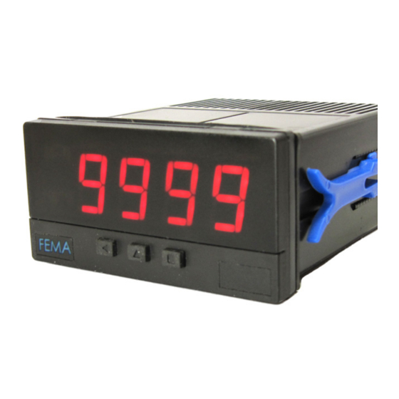
Page 3: Front View
FEMA ELECTRÓNICA . Series S . S40-R 1.2 Front view 1.5 Signal connections Alarms Connections for potentiometers and ratiometric sensors 1 2 3 Vexc. +5V Signal Logo Units Common Button ‘LE’ Button ‘UP’ Button ‘SQ’ Connections for potentiometers and ratiometric, in passive mode ‘Fast access‘... -
Page 4: Technical Specifications
FEMA ELECTRÓNICA . Series S . S40-R 1.7 Technical specifications Digits Functions included Section number of digits 7 segments led Segment linearization up to 20 segments 1.10.5 color red or green Display filters recursive 1.10.4 digit height 14 mm steps fixed digits Reading left zeros... -
Page 5: How To Operate The Menus
FEMA ELECTRÓNICA . Series S . S40-R 1.8 How to operate the menus The instrument has two menus accessible to the user : Example of operation inside the ‘configuration menu’. ‘Configuration menu’ (key SQ) (<) 1. The SQ (<) key enters into the ‘Fast access’... -
Page 6: Configuration Menu
FEMA ELECTRÓNICA . Series S . S40-R 1.10 Configuration menu 1.10.1 Initial set-up Press ‘SQ’ (<) for 1 second to access the ‘configuration menu’. For a description on how to operate inside the menus see sec- tion 1.8. For a full vision of the ‘configuration menu’ structure To configure the initial set up of the instrument, select the type of see section 1.11. -
Page 7: Alarms
FEMA ELECTRÓNICA . Series S . S40-R 1.10 Configuration menu (cont.) 1.10.3 Alarms The ‘Alarms’ (‘ALr’) menu configures the independent activation of Alarms up to 3 relay outputs, installed with the R1 optional modules (see section 2.1). For outputs up to 4 relays, see special modules R2 and R4 at section 2.6. -
Page 8: Display Filters
FEMA ELECTRÓNICA . Series S . S40-R 1.10 Configuration menu (cont.) 1.10.4 Display filters The instrument provides several functions to personalize the reading Display Fixed digits Fix digits of the display values • the ‘Fixed Digits’ (‘FIX.d’) allows to fix each digit to a fixed value. As an example, fix the least significant digit to a ‘0’... -
Page 9: Segment Linearization
FEMA ELECTRÓNICA . Series S . S40-R 1.10 Configuration menu (cont.) 1.10.5 Segment linearization The ‘Segment Linearization’ (‘S.LIn’) menu provides up to 20 seg- Tools ments to linearize non-linear signals. • at the ‘Number of segments’ (‘nuM’) parameter, select the num- Segment Number Value 2 to 20... -
Page 10: Menu 'On Power Up
FEMA ELECTRÓNICA . Series S . S40-R 1.10 Configuration menu (cont.) 1.10.8 Menu ‘On Power Up’ The ‘On Power Up’ (‘on.Pu’) menu configures functions to apply at Tools start-up. It applies only to instrument restart after power loss. It does not apply to instrument restart due to change in configuration. -
Page 11: Factory Reset
FEMA ELECTRÓNICA . Series S . S40-R 1.10 Configuration menu (cont.) Tools 1.10.11 Factory reset Factory reset At the ‘Factory reset’ (‘FAct’) menu, select ‘yes’ to load the default factory configuration for the instrument (see section 1.15). Version 1.10.12 Firmware version Minimum The ‘Version’... -
Page 12: Full Configuration Menu
FEMA ELECTRÓNICA . Series S . S40-R 1.11 Full configuration menu Press ‘SQ’ (<) for 1 second to access the ‘Configuration menu’. See section for a description of each menu entry. 1.10 Relay inverted Ratiometric transducer Input Potentiometer between 200 Ohm and 5 KOhms Locked alarm Potentiometer <5 MOhms Value in KOhms... - Page 13 FEMA ELECTRÓNICA . Series S . S40-R 1.11 Full configuration menu (cont.) No function Key LE Tools Alarm unlock Segment Number Value 2 to 20 linearization of segments Scaling Input 0 Password Display 0 Factory reset Input 1 Display 1 Firmware version Minimum Brightness...
-
Page 14: To Access The Instrument
Operation must be performed by qualified personnel only. 1.13 Modular system S Series panel meters are designed to create a modular system. This modular system allows for addition, replacement or substitution of any of the internal modules conforming the instrument. Below is a graphic explanation for the position of each module. -
Page 15: Precautions On Installation
FEMA ELECTRÓNICA . Series S . S40-R 1.14 Precautions on installation soon as power is connected. The instrument does not have protection fuse, Risk of electrical shock. Instrument terminals can be connected the fuse must be added during installation. to dangerous voltage. The instrument is designed to be panel mounted. -
Page 16: Output And Control Modules
2.1 Module R1 2.2 Module AO The R1 module provides 1 relay output to S Series panel meters. Up The AO module provides 1 analog output with 4/20 mA or 0/10 Vdc to a maximum of 2 R1 modules can be installed in a single instru- configurable output range. -
Page 17: Module Rtu
‘Opt.1’ or ‘Opt.2’, depending on the position the module is installed (see section 1.13). The S4 module can be ordered pre-installed into a S Series panel me- ter, or standalone for delayed installation, as it does not require sol- dering or special configuration. -
Page 18: Module S2
2.6 Modules R2, R4 The S2 module provides a RS-232 communications module for S The R2 and R4 modules provide 2 and 4 relay outputs for S Series Series of panel meters. ASCII protocol with ‘Master’ / ‘Slave’ archi- panel meters. Relays with 3 contacts each, with switching capability tecture. -
Page 19: Other Options
FEMA ELECTRÓNICA . Series S . S40-R 3. Other options 4. Accessories 3.1 Option IP65 4.1 Adapter KA72 Adapter 72 x 72 mm for 72 x 36 mm Front IP65 protection, with sealing instruments. of front filter clips. * opening the front filter removes the IP65 sealing permanently. - Page 20 Panel meters Panel meters Signal converters Standard 96 x 48 mm Miniature 48 x 24 mm Panel meters Large format meters Bar meters Compact 72 x 36 mm ‘Customized’ Isolators Low cost instruments MODBUS TrueRMS TrueRMS RS-485 Load FEMA ELECTRÓNICA, S.A. Altimira 14 - Pol.
Need help?
Do you have a question about the S Series and is the answer not in the manual?
Questions and answers