Table of Contents
Advertisement
Quick Links
Series S . S40-LC
Panel meter for load cells
DIGITAL PANEL METERS
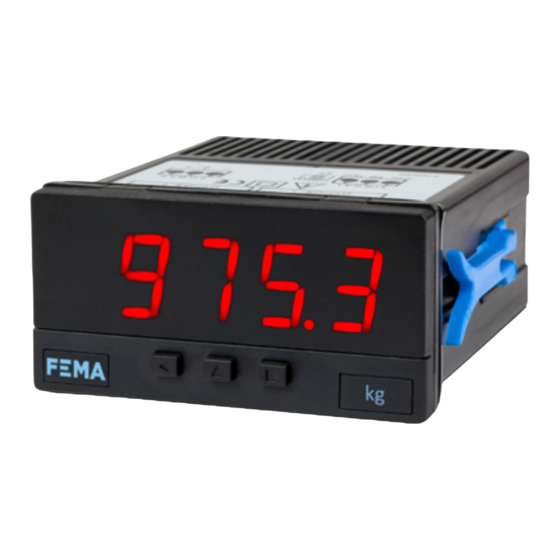
Digital panel meter with compact size, for load cells. Provides excitation voltage to power up to 8
cells. Standard 72 x 36 mm size (1/8 DIN). Reading with 4 digit display and 14 mm digit height. Accepts
4 and 6 wire load cells, includes 'sense' function, fast access to alarm setpoints, tare and 'auto-tare'
functions, 'on power up' functions, stability alarms, configurable operator menu, configurable led
brightness. Universal AC and DC power. Up to 2 optional modules for output and control (relays, tran-
sistor, control SSR, analog outputs, Modbus RTU communications, RS-485 ASCII, RS-232, ...)
4621r02
ELECTRONICS
FOR
PANEL METERS . SIGNAL CONVERTERS . LARGE DISPLAYS
Tel. (+34) 93.729.6004 info@fema.es
User's Manual
INDUSTRIAL
AUTOMATION
www.fema.es
Advertisement
Table of Contents

Subscribe to Our Youtube Channel
Related Manuals for Fema Electronica S40-LC


Summary of Contents for Fema Electronica S40-LC
- Page 1 ELECTRONICS INDUSTRIAL AUTOMATION PANEL METERS . SIGNAL CONVERTERS . LARGE DISPLAYS Series S . S40-LC Panel meter for load cells DIGITAL PANEL METERS Digital panel meter with compact size, for load cells. Provides excitation voltage to power up to 8 cells.
-
Page 2: How To Use This Manual
FEMA ELECTRÓNICA . SERIES S . S40-LC 1. Panel meter S40-LC Panel meter for load cells, compact size 72 Digital panel meter, with 72 x 36 mm compact size and Functions included : 14 mm digit height, for load cell signals. Provides excita- tare accessible from frontal key or rear contact (see sec- •... -
Page 3: How To Order
FEMA ELECTRÓNICA . SERIES S . S40-LC 1.2 Index 1. Panel meter S40-LC....2 1.12.14 ‘On power up’ function..18 1.1 How to use this manual . -
Page 4: Front View
FEMA ELECTRÓNICA . SERIES S . S40-LC 1.4 Material included 1.6 Front view The shipment includes : Alarms and ‘A’,‘B’ leds - 1 instrument S40-LC - 1 pack of orange power terminals - 1 pack of green signal terminals - 1 user’s manual... -
Page 5: Signal And Power Connections
FEMA ELECTRÓNICA . SERIES S . S40-LC 1.8 Signal and power connections 1 2 3 4 5 6 7 8 9 0 Vexc+ Sense+ Neutral AC / Negative DC Signal+ Not connected Signal- Phase AC / Positive DC Sense- Figure 3 - Power connections... -
Page 6: Technical Specifications
FEMA ELECTRÓNICA . SERIES S . S40-LC 1.9 Technical specifications Digits step response see Table 2 number of digits 0 % to 99 % signal 7 segments signal terminals plug-in screw terminals (pitch 3.81 m m) color red or green Power digit height 14 mm... -
Page 7: Signal Ranges
FEMA ELECTRÓNICA . SERIES S . S40-LC 1.9 Technical data (cont.) 1.9.4 Mechanical dimensions (mm (in)) 1.9.2 Signal ranges The instrument works with 6 internal signal ranges and the active range is automatically selected when the in- strument is started. The selection depends on the value of the two parameters : ‘Sensitivity’... - Page 8 FEMA ELECTRÓNICA . SERIES S . S40-LC 1.10 Included functions 1.11 ‘Tare’ functions included Activate the tare function to force the instrument to take the Included functions Section actual signal as a ‘0’ weight. The tare function does not mod-...
- Page 9 FEMA ELECTRÓNICA . SERIES S . S40-LC 1.12 Configuration 1.12.1 How to operate the menus The instrument has two menus accessible to the user : leaves from the configuration menu. Then changes are ap- plied and the instrument is back to normal function. When ‘Configuration menu’...
-
Page 10: Initial Setup
FEMA ELECTRÓNICA . SERIES S . S40-LC 1.12.2 Initial set-up Before starting to configure the instrument, identify the pa- correct the individual deviations of this particular load cell. rameters of the load cell, at the manufacturers datasheet (see For the empirical configuration you will need access to two Table 5). -
Page 11: Initial Setup Menu
FEMA ELECTRÓNICA . SERIES S . S40-LC 1.12.3 Initial setup menu At the initial set up of the instrument, first configure the Press ‘SQ’ (<) for 1 second to access the ‘con- figuration menu’. For a description on how to op- theoretical part of the load cell at the ‘Load cell param-... -
Page 12: Scale Factor
FEMA ELECTRÓNICA . SERIES S . S40-LC 1.12.4 Function ‘auto-tare’ 1.12.6 Function ‘stock’ The ‘auto-tare’ function automatically activates the ‘tare’ The ‘Stock units’ (‘Stck’) function is provided to count large when the weight is removed from the load cell. The ‘auto- quantities of small units, in situations such as stock invento- tare’... -
Page 13: Advanced Configuration Menu
FEMA ELECTRÓNICA . SERIES S . S40-LC 1.12.7 Advanced configuration menu At the ‘Auto-tare’ (‘Aut.t’) menu configure the activation val- ue and stability values to control the automatic activation of the tare, when weight is removed from the cell. See section Advanced conf. - Page 14 FEMA ELECTRÓNICA . SERIES S . S40-LC 1.12.8 Alarms The instrument manages 2 independent internal alarms, each Reading one controlling the activation of an optional relay, transistor or SSR control output. These outputs are optional (see section setpoint hysteresis 2) and are installed at the free slots of the instrument (see section 1.18).
-
Page 15: Alarm Configuration
FEMA ELECTRÓNICA . SERIES S . S40-LC 1.12.9 Alarm configuration Alarms 1, 2 and 3 are configured from menu ‘ALr1’, ‘ALr2’ or ‘ALr3’. See section 1.12.8 for additional information. Alarms • at the ‘Active’ (‘Act’) parameter select ‘on’ • at the ‘Type of alarm’ (‘TypE’) parameter, select ‘MAX’... -
Page 16: Display Filters
FEMA ELECTRÓNICA . SERIES S . S40-LC 1.12.10 Display filters The instrument provides several functions to act upon the reading in order to increase stability, reduce noise and adapt to particular needs. These functions are grouped under the Display Fixed digits Fix digits ‘Display’... -
Page 17: Rear Controls
FEMA ELECTRÓNICA . SERIES S . S40-LC 1.12.11 Rear controls The instrument provides a digital ‘on/off’ input at the rear terminals, referenced as ‘EK’ (see section 1.8). Assign func- tions to this terminal and activate these functions with a short... -
Page 18: Fast Access
FEMA ELECTRÓNICA . SERIES S . S40-LC 1.12.13 Fast access The ‘fast access’ is an operator configurable menu. When • access to maximum and minimum memories from the configured, the operator can access the most usual functions front key ‘UP’ (5) allows to visualize the values. To reset the with a single press of the front key ‘UP’... - Page 19 FEMA ELECTRÓNICA . SERIES S . S40-LC 1.12.15 ‘Fast access’ configuration menu At the ‘Key UP (‘fast access’)’ (‘K.uP’) menu configure which functions and parameters will be accessible through the ‘fast access’ menu. Select ‘on’ to activate each function. See sec- Key UP Setpoint 1...
- Page 20 FEMA ELECTRÓNICA . SERIES S . S40-LC 1.12.17 Tools The ‘Tools’ (‘tooL’) menu groups functions with a variety of uses. at the ‘Password’ (‘PASS’) function define a 4 digit code to Tools Password • block access to the ‘configuration menu’. Activate the pass- word to prevent access to the instrument configuration by non authorized personnel.
- Page 21 FEMA ELECTRÓNICA . SERIES S . S40-LC...
-
Page 22: Full Configuration Menu
FEMA ELECTRÓNICA . SERIES S . S40-LC 1.13 Full configuration menu Press ‘SQ’ (<) for 1 second to access the ‘con- figuration menu’. Standard Mode 50 Hz Load cell Initial conf. 60 Hz Deci mal point parameters Nominal weight Sensitivity... - Page 23 FEMA ELECTRÓNICA . SERIES S . S40-LC Display Fixed digits Fix digits Key LE Tare Alarm unlock Average filter 0 to 100 Stock units Steps Left zeros Key UP Setpoint 1 (fast access) Memory of Setpoint 2 maximum Stock units Memory of...
- Page 24 FEMA ELECTRÓNICA . SERIES S . S40-LC 1.14 Full configuration menu (cont) On power-up Delay Seconds Tare Tools Password Factory configuration Reset ‘initial conf.’ Version Minimum Brightness Standard Maximum Access to the optional module installed at slot 1 Option 1 Access to the optional module installed at slot 2 Option 2...
-
Page 25: Factory Configuration
FEMA ELECTRÓNICA . SERIES S . S40-LC 1.14 Factory configuration 1.15 Messages and errors Initial configuration (‘InIt’) Error messages are informed flashing on display. Load cell parameters (‘cELL’) Decimal point (‘dP’) without (XXXX) Sensitivity mV/V (‘MV.V’) 2.000 Messages and errors Nominal weight(‘LoAd’) - Page 26 FEMA ELECTRÓNICA . SERIES S . S40-LC 1.16 Practical cases 1.16.1 Normal case 1.16.3 Connections with a junction box Case for 1 load cell, powered from the instrument, with A ‘junction box’ for load cells has internal elec- power 10 Vdc, nominal weight 100 Kg and 2 mV/V sensi- tronics that can modify the ‘signal / weight’...
- Page 27 FEMA ELECTRÓNICA . SERIES S . S40-LC 1.16 Practical cases (cont.) 1.16.5 Measuring mV at the laboratory 1.16.4 Connections with 3 or 4 load cells Using 3 load cells is the optimal way to distribute the If you wish to configure the instrument to measure a mil-...
-
Page 28: To Access The Instrument
FEMA ELECTRÓNICA . SERIES S . S40-LC 1.17 To access the instrument To open the housing and access the internal circuits, use a flat screwdriver to unlock the upper clips ‘A’. Then un- lock the lower clips ‘B’ and remove the front cover. Let the inside of the instrument slide out of the housing. -
Page 29: Precautions On Installation
FEMA ELECTRÓNICA . SERIES S . S40-LC 1.19 Precautions on installation 1.21 CE declaration of conformity Manufacturer FEMA ELECTRÓNICA, S.A. Risk of electrical shock. Instrument terminals Altimira 14 - Pol. Ind. Santiga can be connected to dangerous voltage. E08210 - Barberà del Vallès Instrument protected with double isolation. -
Page 30: Output And Control Modules
FEMA ELECTRÓNICA . SERIES S . S40-LC 2. Output and control modules 2.1 Module R1 2.2 Module T1 The R1 module provides 1 relay output, to install on Series The T1 module provides 1 transistor output, to install on Se-... -
Page 31: Module Ssr
FEMA ELECTRÓNICA . SERIES S . S40-LC 2.3 Module SSR 2.4 Module AO The SSR module provides 1 output to control an SSR relay, to The AO module provides 1 isolated analog output, configu- install on Series S meters, up to a maximum of 2 SSR outputs rable for 4/20 mA or 0/10 Vdc, to install on Series S meters,... -
Page 32: Module Rtu
FEMA ELECTRÓNICA . SERIES S . S40-LC 2.5 Module RTU 2.6 Module S4 The RTU module provides 1 isolated RS-485 Modbus RTU out- The S4 module provides 1 isolated RS-485 ASCII output, to in- put, to install on Series S meters. - Page 33 FEMA ELECTRÓNICA . SERIES S . S40-LC 2.7 Module S2 2.8 Modules R2, R4, R6 The S2 module provides 1 isolated RS-232 ASCII output, to in- Special modules R2 and R4 offer 2 and 4 relay outputs, to in- stall on Series S meters.
-
Page 34: Other Options
FEMA ELECTRÓNICA . SERIES S . S40-LC 3. Other options 3.1 Option G Option with green leds Green leds... - Page 35 FEMA ELECTRÓNICA . SERIES S . S40-LC 4. Accessories 4.1 Adapter KA72 4.2 Units-8 Labelling units Adapter 72 mm for 72 (g, kg, t, pcs, mg, lb, N, kN) instruments.
Need help?
Do you have a question about the S40-LC and is the answer not in the manual?
Questions and answers