Table of Contents
Advertisement
Quick Links
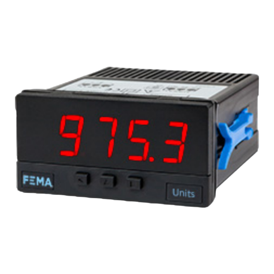
Series S . S40-P
Panel meter for process signals
PANEL METERS
Panel meter for process signals in mA and Vdc, in compact size 72 x 36 mm, and standard 14 mm digit
height. Provides configurable excitation voltage to power-up the transducer. Reading with 4 digit
display. Segment linearization, fast access to alarm setpoints, tare function, 'on power up' function,
'measure' function, configurable reading brightness. Universal AC and DC power. Up to 2 optional
modules for output and control (relays, transistor, control SSR, analog outputs, Modbus RTU commu-
nications, RS-485 ASCII, RS-232, ...)
1103r14
ELECTRONICS
FOR
PANEL METERS . SIGNAL CONVERTERS . LARGE DISPLAYS
Tel. (+34) 93.729.6004 info@fema.es
User's Manual
INDUSTRIAL
AUTOMATION
www.fema.es
Advertisement
Table of Contents

Related Manuals for Fema Electronica S40-P


Summary of Contents for Fema Electronica S40-P
- Page 1 ELECTRONICS INDUSTRIAL AUTOMATION PANEL METERS . SIGNAL CONVERTERS . LARGE DISPLAYS Series S . S40-P Panel meter for process signals PANEL METERS Panel meter for process signals in mA and Vdc, in compact size 72 x 36 mm, and standard 14 mm digit height. Provides configurable excitation voltage to power-up the transducer. Reading with 4 digit display.
-
Page 2: Table Of Contents
Index 1. Panel meter S40-P ..... . . 2 1.10.14 Firmware version....11 1.1 How to order . -
Page 3: Front View
FEMA ELECTRÓNICA . Series S . S40-P 1.2 Front view 1.5 Signal connections Alarms Bucle de corriente activo 4/20 mA, ±20 mA 1 2 3 Jumper 5 cerrado Señal Común Logo Units Bucle de corriente pasivo 4/20 mA, ±20 mA 1 2 3 Jumper 5 cerrado Button ‘UP’... -
Page 4: Technical Specifications
FEMA ELECTRÓNICA . Series S . S40-P 1.7 Technical specifications Digits Functions included Section number of digits 7 segments led Segment linearization up to 20 segments 1.10.5 color red or green Display filters recursive 1.10.4 digit height 14 mm steps fixed digits... -
Page 5: How To Operate The Menus
FEMA ELECTRÓNICA . Series S . S40-P 1.8 How to operate the menus The instrument has two menus accessible to the user : Example of operation inside the ‘configuration menu’. ‘Configuration menu’ (key SQ) (<) 1. The SQ (<) key enters into the ‘Fast access’... -
Page 6: Configuration Menu
FEMA ELECTRÓNICA . Series S . S40-P 1.10 Configuration menu 1.10.1 Initial set-up Press ‘SQ’ (<) for 1 second to access the ‘configuration menu’. For a description on how to operate inside the menus see sec- tion 1.8. For a full vision of the ‘configuration menu’ structure To configure the initial set up of the instrument, select the input sig- see section 1.11. -
Page 7: Alarms
FEMA ELECTRÓNICA . Series S . S40-P 1.10 Configuration menu (cont.) 1.10.3 Alarms The ‘Alarms’ (‘ALr’) menu configures the independent activation of Alarms up to 2 relay outputs (or transistor or control SSR), installed with the R1 (or T1 or SSR) optional modules (see section 2.1). For outputs up to 4 relays, see special modules R2 and R4 at section 2.8. -
Page 8: Display Filters
FEMA ELECTRÓNICA . Series S . S40-P 1.10 Configuration menu (cont.) 1.10.4 Display filters The instrument provides several functions to personalize the reading Display Fixed digits Fix digits of the display values • the ‘Fixed Digits’ (‘FIX.d’) allows to fix each digit to a fixed value. -
Page 9: Segment Linearization
FEMA ELECTRÓNICA . Series S . S40-P 1.10 Configuration menu (cont.) 1.10.5 Segment linearization The ‘Segment Linearization’ (‘S.LIn’) menu provides up to 20 seg- Tools ments to linearize non-linear signals. • at the ‘Number of segments’ (‘nuM’) parameter, select the num-... -
Page 10: Menu 'On Power Up
FEMA ELECTRÓNICA . Series S . S40-P 1.10 Configuration menu (cont.) 1.10.8 Menu ‘On Power Up’ The ‘On Power Up’ (‘on.Pu’) menu configures functions to apply at Tools start-up. It applies only to instrument restart after power loss. It does not apply to instrument restart due to change in configuration. -
Page 11: Excitation Voltage
FEMA ELECTRÓNICA . Series S . S40-P 1.10 Configuration menu (cont.) 1.10.11 Excitation voltage At the ‘Excitation Volt’ (‘V.EXc’) menu select the excitation voltage Tools value at 5 Vdc, 10 Vdc, 15 Vdc or 20 Vdc. Select ‘oFF’ to disable the excitation voltage. 1.10.12 Function ‘Password’... -
Page 12: Full Configuration Menu
FEMA ELECTRÓNICA . Series S . S40-P 1.11 Full configuration menu Press ‘SQ’ (<) for 1 second to access the ‘Configuration menu’. See section for a description of each menu entry. 1.10 Relay inverted Range 4/20 mA Input Locked alarm Range 0/10 Vdc Range ±20 mA... - Page 13 FEMA ELECTRÓNICA . Series S . S40-P 1.11 Full configuration menu (cont.) Tare function Reset Tools Segment Number Value 2 to 20 Key LE No function linearization of segments Tare Scaling Input 0 Alarm unlock Display 0 Input 1 Excitation Volt. Display 1 Activate...
-
Page 14: To Access The Instrument
FEMA ELECTRÓNICA . Series S . S40-P 1.12 To access the instrument You may need to access the inside of the instrument to add or re- place internal modules. Use a flat screwdriver to unlock the upper clips marked with ‘A’. Then unlock the lower clips marked with ‘B’ and remove the front cover. -
Page 15: Precautions On Installation
FEMA ELECTRÓNICA . Series S . S40-P 1.14 Precautions on installation clean by using a humid rag and do NOT use abrasive products such as alcohols, solvents, Risk of electrical shock. Instrument terminals can be connected etc. to dangerous voltage. -
Page 16: Output And Control Modules
FEMA ELECTRÓNICA . Series S . S40-P 2. Output and control modules 2.1 Module R1 2.2 Module T1 The R1 module provides 1 relay output to to install at digital panel The T1 module provides 1 transistor output to install at digital panel meters from Series S, up to a maximum of 2 relays in a single meter. -
Page 17: Module Ssr
FEMA ELECTRÓNICA . Series S . S40-P 2.3 Module SSR 2.4 Module AO The SSR module provides 1 output to control SSR relays, to install at The AO module provides 1 analog output with 4/20 mA or 0/10 Vdc digital panel meters from Series S, up to a maximum of 2 SSR con- configurable output range. -
Page 18: Module Rtu
FEMA ELECTRÓNICA . Series S . S40-P 2.5 Module RTU 2.6 Module S4 The S4 module provides a RS-485 communications module for Series The RTU module provides a Modbus RTU communications module for Series S of panel meters. The RTU module implements function S of panel meters. -
Page 19: Module S2
FEMA ELECTRÓNICA . Series S . S40-P 2.7 Module S2 2.8 Modules R2, R4 The S2 module provides a RS-232 communications module for Series The R2 and R4 modules provide 2 and 4 relay outputs for Series S S of panel meters. ASCII protocol with ‘Master’ / ‘Slave’ architecture.
Need help?
Do you have a question about the S40-P and is the answer not in the manual?
Questions and answers