Fema Electronica K Series User Manual
Hide thumbs
Also See for K Series:
- User manual (37 pages) ,
- User manual (28 pages) ,
- User manual (24 pages)
Table of Contents
Advertisement
Quick Links
Series K . K40-232
Display for serial protocol RS-232 ASCII
PANEL METERS
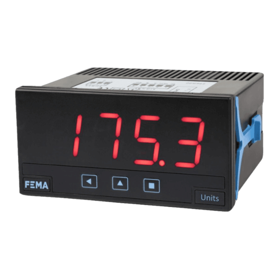
Display for ASCII protocol with RS-232 communications bus, with 4 digits and 20 mm digit height,
in red color. Reading range from 9999 to -1999 with decimal point. Local or remote alarm control.
'Watchdog' function and 'bus activity' function. Standard 96 x 48 mm size (1/8 DIN). Fast access to
'bus ativity', alarm setpoints and memory of max and min. 'On power up' function, configurable read-
ing brightness, password. Universal AC and DC power. Up to 3 optional modules for output and con-
trol (relays, transistor, control SSR, analog outputs, Modbus RTU communications, RS-485 ASCII, RS-
232, ...)
3821r03
ELECTRONICS
FOR
PANEL METERS . SIGNAL CONVERTERS . LARGE DISPLAYS
Tel. (+34) 93.729.6004 info@fema.es
User's Manual
INDUSTRIAL
AUTOMATION
www.fema.es
Advertisement
Table of Contents

Related Manuals for Fema Electronica K Series


Summary of Contents for Fema Electronica K Series
- Page 1 User’s Manual ELECTRONICS INDUSTRIAL AUTOMATION PANEL METERS . SIGNAL CONVERTERS . LARGE DISPLAYS Series K . K40-232 Display for serial protocol RS-232 ASCII PANEL METERS Display for ASCII protocol with RS-232 communications bus, with 4 digits and 20 mm digit height, in red color.
-
Page 2: Table Of Contents
FEMA ELECTRÓNICA . Series K . K40-232 1. Panel meter K40-232 Display for ASCII protocol with RS-232 bus, in 96 mm (1/8 DIN) format Digital panel meter, with ASCII code repeater function, in 96 x 48 mm Bus speed configurable up to 38.400 bps and address configurable size (1/8 DIN) and 4 digits with 20 mm digit height. -
Page 3: How To Order
FEMA ELECTRÓNICA . Series K . K40-232 1.1 How to order Model Power Option 1 Option 2 Option 3 Others -NBT (85-265 Vac/dc) (1 relay) (no buttons) (11/60 Vdc, (analog output) (front IP65) 24 Vac, 48 Vac) -RTU (Modbus RTU) (green led) (RS-485) (RS-232) (1 transistor) -SSR (1 control SSR) (empty) 1.2 ‘Process slave’... -
Page 4: Front View
FEMA ELECTRÓNICA . Series K . K40-232 1.6 Front view 1.9 Rear view Option 3 Option 1 Option 2 Alarms Logo Units Signal Power Button ‘UP’ Button ‘SQ’ Button ‘LE’ (see section 1.10) (see section 1.7) ‘Fast access‘ ‘Configuration menu’ (see section 1.28.6) (see section 1.28) Detail of the plug-in screw terminals provided with the instrument. -
Page 5: Technical Specifications
FEMA ELECTRÓNICA . Series K . K40-232 1.11 Technical specifications Protocol ASCII Functions included Section RS-232 Speed from 38.400 bps to 600 bps Fast access yes, configurable 1.28.6 (19.200 bps by default) Watchdog yes, configurable 1.25 Data format 8n1, 8e1, 8o1, 8n2 Address 1 to 31 Scroll in ‘Text’... -
Page 6: Ascii Protocol - Types Of Frames
FEMA ELECTRÓNICA . Series K . K40-232 1.13 ASCII protocol - Types of frames The ASCII protocol used defines the following types of frames : • Frame ‘read’ (‘RD’). Identifier 36. Frame to request the data value of a register. The register number is indicated in the ‘REG’ byte (sec- •... -
Page 7: Frame Structure
FEMA ELECTRÓNICA . Series K . K40-232 1.14 Frame structure Header Data Trail FROM LONG [data] The protocol frames are structure with a header section (‘Header’), a Section ‘Trail’ data section (‘Data’) and a end of frame section (‘Trail’). Contains the ‘CRC’ code and the end of frame byte (‘ETX’). Section ‘Header’... -
Page 8: Frame Examples
FEMA ELECTRÓNICA . Series K . K40-232 1.15 Frame examples 1.15.1 Frames ‘WRA’ (35) and ‘OK’ (39) Example - The ‘Master’ (address ‘0’) sends a write frame, with re- ‘Slave’ answers to the ‘Master’ with a ‘ok’ frame (‘OK’). In case of quest of acknowledgment, (frame ‘WRA’) with value ‘65.43’... -
Page 9: Frames 'Rd' (36) And 'Ans' (37)
FEMA ELECTRÓNICA . Series K . K40-232 1.15 Frame examples (cont.) 1.15.4 Frames ‘RD’ (36) and ‘ANS’ (37) Example - The ‘Master’ (address ‘0’) requests the value of register that contains the value requested (65.43). For compatibility reasons, number ‘0’ (display value) to the ‘Slave’ with address ‘28’ (frame de instrument will always answer with a 6 digit value, filling with left ‘RD’) and the ‘Slave’... -
Page 10: Registers In 'Process Slave' Mode
FEMA ELECTRÓNICA . Series K . K40-232 1.16 Registers in ‘Process slave’ mode List of registers accessible (see Table 3) for an instrument configured and write access to these registers through the bus, see section in ‘Process slave’ mode. 1.28.9. •... -
Page 11: Registers In 'Text' Mode
FEMA ELECTRÓNICA . Series K . K40-232 1.18 Registers in ‘Text’ mode List of registers accessible (see Table 5) for an instrument configured • if the register contains more than 6 characters, the ‘scroll’ mode is activated (see section 1.28.3). in ‘Text’... -
Page 12: The 'Alarm Status' Register
FEMA ELECTRÓNICA . Series K . K40-232 1.20 The ‘Alarm status’ register The ‘Alarm Status’ register (register 6) is available as a read_only reg- Register ASCII Alarm 3 Alarm 2 Alarm 1 ister for the ‘Process slave’ mode and as a read/write register for value character status... -
Page 13: Messages And Errors
FEMA ELECTRÓNICA . Series K . K40-232 1.22 Messages and errors Error messages are grouped into those related to the instrument, • error messages related to the communications protocol are and those related to the frames informed into the response frame (see Table 9). Error messages are generated only as answers to frames ‘WRA’... -
Page 14: Numerical Registers : Restrictions
FEMA ELECTRÓNICA . Series K . K40-232 1.23 Numerical registers : restrictions 1.24 Addresses and ‘broadcast’ Registers which must contain a numerical value, are controlled to as- Addresses available to assign to the intruments are from 1 to 31. Ad- sure that the value received from the frame is a true numerical value. -
Page 15: How To Operate The Menus
FEMA ELECTRÓNICA . Series K . K40-232 1.27 How to operate the menus The instrument has two menus accessible to the user : Example of operation inside the ‘configuration menu’. ‘Configuration menu’ (key SQ) (<) 1. The SQ (<) key enters into the ‘Fast access’... -
Page 16: Configuration Menu
FEMA ELECTRÓNICA . Series K . K40-232 1.28 Configuration menu Press ‘SQ’ (<) for 1 second to access the ‘configuration menu’. 1.28.1 Initial set-up For a description on how to operate inside the menus see section 1.27 . For a full vision of the ‘configuration menu’ structure see The instrument can work in two different modes called ‘Process 1.30 section... -
Page 17: Configuration
FEMA ELECTRÓNICA . Series K . K40-232 1.28 Configuration menu (cont.) 1.28.3 Configuration 1 to 31 In configuration menu assign the instrument address, the ‘watchdog’ Configuration Local address time, define the behavior in case of error, and configure the scroll function for ‘Text’... -
Page 18: Alarms In 'Process Slave' Mode
FEMA ELECTRÓNICA . Series K . K40-232 1.28 Configuration menu (cont.) 1.28.5 Alarms in ‘Process slave’ mode Alarms in ‘pro- Menu available only in ‘Process slave’ mode. Alarms are locally con- cess slave’ mode trolled from the instrument. Operator must manually configure the alarm parameters for each alarm. -
Page 19: Fast Access
FEMA ELECTRÓNICA . Series K . K40-232 1.28 Configuration menu (cont.) 1.28.6 Fast access The ‘UP’ (5) key at the front of the instrument gives access to a list Tools of functions configurable by the operator. See section 1.27 for an ex- planation on how to operate the ‘fast access’... -
Page 20: Menu 'Save To E2Prom
FEMA ELECTRÓNICA . Series K . K40-232 1.28 Configuration menu (cont.) 1.28.10 Menu ‘Save to E2PROM’ By default, saving values to the E2PROM from the communciations Remote SAve to E2PROM bus, is disabled. Select ‘on’ to save updates on the setpoint values also to the E2PROM (see section 1.28.9). -
Page 21: Factory Configuration
FEMA ELECTRÓNICA . Series K . K40-232 1.29 Factory configuration Working mode ‘Process slave’ (‘Proc’) Speed 19200 bps Format Configuration Local address ‘Watchdog’ 10 seconds ‘On error’ flash (‘FLSh’) Scroll Alarms in ‘Full slave’ and ‘Text’ modes Alarm 1 remote (‘rMtE’) Alarm 2 remote (‘rMtE’) Alarm 3... -
Page 22: Full Configuration Menu
FEMA ELECTRÓNICA . Series K . K40-232 1.30 Full configuration menu Press ‘SQ’ (<) for 1 second to access the ‘configuration menu’. See 1.28 section . for a description of each menu entry. Alarms in Alarm 1 Remote ‘Process slave’ mode ‘full slave’... - Page 23 FEMA ELECTRÓNICA . Series K . K40-232 1.30 Full configuration menu (cont.) Tools Password Key UP Bus activity (‘fast access’) Factory reset Memory of maximum Version Memory of minimum Minimum Brightness Setpoint 1 Standard Setpoint 2 Maximum Setpoint 3 Configuration menu for the module installed at Opt.1 Address ...
-
Page 24: To Access The Instrument
Operation must be performed by qualified personnel only. 1.32 Modular system K Series panel meters are designed to create a modular system. This modular system allows for addition, replacement or substitution of any of the internal modules conforming the instrument. Below is a graphic explanation for the position of each module. -
Page 25: Precautions On Installation
FEMA ELECTRÓNICA . Series K . K40-232 1.33 Precautions on installation 1.35 CE declaration of conformity Manufacturer FEMA ELECTRÓNICA, S.A. Risk of electrical shock. Instrument terminals can be connected Altimira 14 - Pol. Ind. Santiga to dangerous voltage. E08210 - Barberà del Vallès BARCELONA - SPAIN Instrument protected with double isolation. -
Page 26: Output And Control Modules
FEMA ELECTRÓNICA . Series K . K40-232 2. Output and control modules 2.1 Module R1 2.2 Module T1 The R1 module provides 1 relay output to to install at digital panel The T1 module provides 1 transistor output to install at digital panel meters from Series K, up to a maximum of 3 relays in a single meter. -
Page 27: Module Ssr
FEMA ELECTRÓNICA . Series K . K40-232 2.3 Module SSR 2.4 Module AO The SSR module provides 1 output to control SSR relays, to install at The AO module provides 1 analog output with 4/20 mA or 0/10 Vdc digital panel meters from Series K, up to a maximum of 3 SSR con- configurable output range. -
Page 28: Module Rtu
FEMA ELECTRÓNICA . Series K . K40-232 2.6 Module RTU 2.5 Module S4 The S4 module provides a RS-485 communications module for Series The RTU module provides a Modbus RTU communications module for Series M of panel meters. The RTU module implements function M of panel meters. -
Page 29: Module S2
FEMA ELECTRÓNICA . Series K . K40-232 2.7 Module S2 2.8 Modules R2, R4, R6 The S2 module provides a RS-232 communications module for Series The R2, R4 and R6 modules provide 2, 4 and 6 relay outputs for Series M of panel meters. -
Page 30: Other Options
FEMA ELECTRÓNICA . Series K . K40-232 3. Other options 3.1 Option NBT Instruments without front key- pad. To configure the instrument, remove the meter from the panel and remove the front filter. Inter- nal press buttons for configuration are accessible. Optionally, request instrument preconfigured from factory. -
Page 31: Accessories
FEMA ELECTRÓNICA . Series K . K40-232 4. Accessories 4.1 THM benchtop housing 4.4 WME housing Benchtop housing for Series M Wall mount housing. Together and Series K of panel meters. with the KIP protector, offer a Handle with three selectable posi- full IP65 protection.
Need help?
Do you have a question about the K Series and is the answer not in the manual?
Questions and answers