Fema Electronica M Series User Manual
Panel meters 96x48mm
Hide thumbs
Also See for M Series:
- User manual (28 pages) ,
- User manual (24 pages) ,
- User manual (24 pages)
Table of Contents
Advertisement
Quick Links
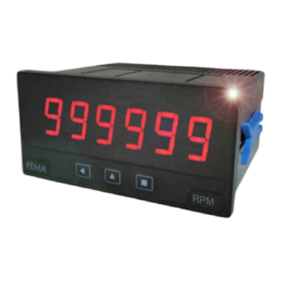
Series M
Panel Meters
Model M40-T
Panel meter for Pt100/RTD (2 and 3 wires), and thermocouples J, K, T, E, S, R, N, C,
L and X with temperature display in degrees celsius (ºC) or fahrenheit (ºF). Selectable
Pt100/RTD resolution at 1º or 0.1º, and manual offset available. Thermocouple measure
with internal CJC selectable (enabled or disabled). Selectable behavior in case of
sensor break ('to_high' or 'to_low'). Size 96x48mm. Reading with 4 digits. Maximum
and minimum display memory, steps, alarms with single or double setpoints, 5 levels
of brightness, ... Universal AC and DC power modules and up to 3 modules for signal
retransmission and control (relay outputs, analogue outputs, ...).
USER'S MANUAL
(2185R04)
Panel meters 96x48mm
Pt100/RTD
Thermocouples
Advertisement
Table of Contents

Related Manuals for Fema Electronica M Series


Summary of Contents for Fema Electronica M Series
- Page 1 Series M Panel Meters Panel meters 96x48mm Model M40-T Pt100/RTD Thermocouples Panel meter for Pt100/RTD (2 and 3 wires), and thermocouples J, K, T, E, S, R, N, C, L and X with temperature display in degrees celsius (ºC) or fahrenheit (ºF). Selectable Pt100/RTD resolution at 1º...
-
Page 2: Table Of Contents
User’s Manual M40-T 1. Meter M40-T Panel meter 96x48mm size for Pt100/RTD and thermocouples Panel meter for temperature signals, accepts Pt100/RTD with Power options with universal AC and DC ranges, and space 2 and 3 wires, and thermocouples J, K, T, E, S, R, N, C, L and for 3 additional control and/or signal retransmission modules. -
Page 3: Front View
User’s Manual M40-T 1.2 Front View 1.5 Signal connections - Pt100 / RTD Alarms Measure can be selected for 2 or 3 wire systems. 1 2 3 Select input Pt100 2Wires in the menu. Terminal 2 can be left un- connected. -
Page 4: Technical Data
User’s Manual M40-T 1.7 Technical data 1.7 Technical data (cont.) Digits Power Type 7 segments, red Power “H” 85 to 265 Vac/dc Height 14 mm Power “L” 11 to 60 Vdc and 24/48Vac Display maximum 9999 Consumption <4W Display minimum -9999 Isolation 3500Veff for power “H”... -
Page 5: Mechanical Dimensions (Mm)
User’s Manual M40-T 1.8 Mechanical dimensions (mm) Panel cut-out FEMA ELECTRÓNICA - Page 5... -
Page 6: Operating The Menus
User’s Manual M40-T 1.9 Operating the menus 1.10 Configuration menu The instrument has two menus accessible to the user : Press SQ button to enter Configuration Menu “Configuration Menu” (key SQ) Pt100/RTD 2 wires “Information Menu” (key UP) Input Pt100/RTD 3 wires The “Configuration Menu”... -
Page 7: Configuration Menu (Cont.)
User’s Manual M40-T 1.10 Configuration menu (cont.) Alarms Tools Password Select password Al. active Alarm1 Active Al. inactive Factory Apply configuration Alarm as max. Alarm type Alarm as min. Firmware version Version Setpoint Minimum Brightness Counts Hysteresis Standard Seconds Delay Maximum Setpoint2 Second setpoint... -
Page 8: Input Menu
User’s Manual M40-T Hysteresis (HYSt) - Value from “0” to “9999”. Points of hyster- 1.10.1 Input menu esis. The hysteresis applies on the deactivation of the alarm. The input menu selects the input signal range. Options avail- Delay (DEL) - Value from “0.0” to “99.9” seconds. Delay to be able are Pt100/RTD 2 or 3 wires, and thermocouples J, K, T, applied to the relay activation and deactivation. -
Page 9: Menu Optx - Options
User’s Manual M40-T 1.10.6 Menu OptX - Options 1.11 Default factory configuration Menu options OPT1, OPT2 and OPT3 give access to the Sensor Pt100 2Wire configuration menus of the options installed at slots Opt1, Degrees ºC Opt2 and Opt3. This menu depends on the installed option. Resolution 0.1º... -
Page 10: Information Menu
User’s Manual M40-T 1.13 Information menu 1.13.1 Information menu Configuration (Conf) - Information on the configured input Press UP button to enter Information Menu sensor and the degrees selected. Maximum (MAX) - Value of the maximum display. Configuration Sensor type Minimum (MIn) - Value of the minimum display. -
Page 11: Warranty
User’s Manual M40-T 1.15 Warranty 1.17 CE declaration of conformity All instruments are warranted against all manufacturing Manufacturer FEMA ELECTRÓNICA, S.A. Altimira 14 - Pol. Ind. Santiga defects for a period of 24 MONTHS from the shipment date. E08210 - Barberà del Vallès This warranty does not apply in case of misuse, accident or BARCELONA - SPAIN manipulation by non-authorized personnel. -
Page 12: Output And Control Modules
Module with 1 relay. Up to a maximum of three R1 modules 0/10Vdc. Output signal proportional to the reading. Scal- can be installed in one M Series panel meter. For more re- ing through the frontal keypad. Up to a maximum of three lay output needs, check special modules R2, R4 and R6. -
Page 13: Modules R2, R4, R6
Opt 1 Opt 2 required functionality for your application. Only one special module R2, R4 or R6 can be installed in an M Series panel A B C D E F G H I J K L meter. Special modules R2, R4 and R6 are not compatible with R1 modules. -
Page 14: More Options And Accessories
7.2 Option G Green led option. Green led 7.3 Option IP65 This option provides M series panel meters with IP65 front protection. The instrument is provided with the front cover sealed. NOTE - Removing the front cover to access the inside of the instrument will permanently disable the IP65 protection (see section 1.14). - Page 15 User’s Manual M40-T FEMA ELECTRÓNICA - Page 15...
- Page 16 other products Panel Meters Panel Meters Panel Meters Standard 96x48mm Small 72x36mm Miniature 48x24mm Large Displays Signal Converters Bar Meters 60&100mm digit & Isolators www.fema.es ELECTRONIC INSTRUMENTATION FOR INDUSTRY FEMA ELECTRÓNICA, S.A. Altimira 14 - Pol. Ind. Santiga E08210 Barberà del Vallès BARCELONA - SPAIN Tel.
Need help?
Do you have a question about the M Series and is the answer not in the manual?
Questions and answers