
Subscribe to Our Youtube Channel
Related Manuals for Hioki DSM-8104


Summary of Contents for Hioki DSM-8104
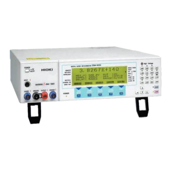
- Page 1 INSTRUCTION MANUAL DSM-8104 DIGITAL SUPER MEGOHMMETER April 2013 Revised edition 1 DS8104A981-01 13-04H...
- Page 3 Preface Thank you for purchasing the DSM-8104 and welcome to the growing family of HIOKI’s Digital Super Megohm Meters/Current Meters. The DSM-8104 is an insulation resistance meter up to 1000V in measuring voltage. Incorrect operation of the meter potentially causes an electric shock or damage to a sample.
- Page 4 Sequence programming function Interlock function GP-IB is a standard provision Handler interface is a standard provision RS-232 is a standard provision About This Operational Manual • Warning, Caution and Notice Important safety precautions and operational instructions are described in this manual under the following headings.
- Page 5 III. Organizational Elements of Operational Manual This operational manual has the following chapters. Please make certain to read the manual carefully before operating the meter. Preparations Before Operation This chapter contains important information such as a check to be made during uncrating, operating power supply and measuring cables.
- Page 6 Safety Precautions FOR SAFE USE OF THE METER • Do the power supply voltage of the meter and commercial power supply voltage to be supplied match? Please check it. Supplying 200V power supply voltage while the power supply voltage of the meter is 100V sometimes causes damage to the meter. •...
-
Page 7: Table Of Contents
Contents 1. Preparations Before Operation ········································································ 1 1.1 Check during Uncrating ················································································· 1 1.2 Operating Power Supply ················································································ 1 1.3 Grounding ····································································································· 2 1.4 Measuring Cable ··························································································· 2 1.5 Warming Up Time·························································································· 2 1.6 Memory Initializing························································································· 2 2. Specification 2.1 Measurement Performance············································································ 3 2.1.1 DC current measurement············································································... - Page 8 5. Preparations for Measurement 5.1 Setting Measuring Conditions ······································································ 20 5.1.1 Screen types ···························································································· 22 5.1.2 Setting measuring mode··········································································· 28 5.1.3 Setting measuring voltage ········································································ 28 5.1.4 Setting current limiter ··············································································· 29 5.1.5 Setting measuring range ·········································································· 30 5.1.6 Setting integral time (sampling time)························································· 31 5.1.7 Setting averaging function ········································································...
- Page 9 7. GP-IB Interface 7.1 Overview ····································································································· 66 7.2 Specification································································································ 66 7.3 Talker Function ··························································································· 67 7.4 Response to Query Program Message ························································ 68 7.5 Listener Function························································································· 69 7.6 Device Clear Function ················································································· 70 7.7 Device Trigger Function ·············································································· 70 7.8 Remote and Local Functions ······································································· 71 7.9 Program Messages······················································································...
- Page 10 10.2.2 Calibration of measuring voltage ·························································· 116 10.2.3 Calibration of current measurement ······················································ 116 10.3 Self-calibration Function ·········································································· 117 10.4 Self-diagnosis Function ··········································································· 118 10.5 Service Organization of HIOKI································································· 119 10.6 Storage and Moving ················································································ 119 11. Product Full View······················································································· 120...
-
Page 11: Preparations Before Operation
Preparations Before Operation Ch eck during Uncrating This product has been inspected carefully at the HIOKI factory in preshipment inspection. Nevertheless, check the following items when uncrating the crate. 1) Any damage on the exteriors of the product. 2) Quantities of accessories Check in accordance with Table 1.1 List of Accessories. -
Page 12: Grounding
However, memory initialization also automatically clears data saved by the save function. Memory initialization will set the values that were set during preshipment inspection at the HIOKI factory shown in Table 7.9 “Settings by Factory Preshipment Inspection and Values Initialized by Message.”... -
Page 13: Specification
[Remarks] The resistance measurement accuracy greatly affects the accuracies of voltage impressed and of current measured. The DSM-8104 specifies only the current accuracy as a specification. The resistance accuracy is calculated by the following formula assuming current measurement is a full-scale value. -
Page 14: Measuring Voltage Output
2.1.2 Measuring voltage output (1) Setting voltage accuracy and resolution Setting Voltage Range Resolution Accuracy 0.1 to 250.0V 100mV ±( 0.1%+ 150mV ) 251 to 1000V ±( 0.1%+ 400mV ) (2) Current limiter Setting Voltage Total Current on Current on Range Value Current... -
Page 15: Self-Calibration Function And Self-Diagnosis Function
2.2.4 Self-calibration function and self-diagnosis function The self-calibration function and self-diagnosis function are executed by keying the Execute key or by the Execute command from the interface. Self-calibration can be executed automatically after setting an interval. Self-diagnosis is executed automatically when the power is turned on. Execution items: Self-calibration: Current range calibration (can be executed automatically) Self-diagnosis: Current range calibration, memory check... -
Page 16: Storage And Display Functions Of Measured Data
2.2.8 Storage and display functions of measured data (1) Measured data buffer Measured data up to 1000 data groups can be sequentially stored. Up to 1000 most recent data groups are stored and displayed on the measurement screen. Note: Stored data is cleared when the power is shut down. (2) Histogram counter Measured values are classified into ten types and numbers of data groups are stored by digitally counting them by a counter. -
Page 17: General Specifications
• Electrical specification Contact input and output by a photocoupler Connector product No. is 57RE-40360-730B (DDK) 2.3 General Specifications General Specifications HIOKI-specification insulation meter input connector (INPUT) Black binding post (GND) Blue binding post (GUARD) -
Page 18: Options
Length 1m, red 0GA00008 Length 1m, black Interlock connection cable DSM8104F Length 1m 2.4.2 Common options The options common to all HIOKI insulation meters are as follows. Option Product Name Remarks Electrode for planar SME-8310 With changeover switch for surface and sample,Ø50 diameter... -
Page 19: Operating Principles
Operating Principles Operating Principles Equipped with a stable measuring voltage source and high-sensitivity current measuring unit, this meter calculates an insulation resistance value based on measuring voltage impressed to the work and measured current value. The meter also outputs a current value and can be used also as a high-sensitivity ammeter embedded with a voltage source. -
Page 20: Block Diagram
Block Diagram... -
Page 21: Names And Functions Of Components
Names and Functions of Components [Notice] In the following descriptions, characters enclosed by “[ ]” such as [ENTER] are the characters printed on key tops. Characters enclosed by “ ” such as “POWER” are the characters printed on the panels. Safety Alert Symbols The following safety alert symbols are placed on the front and rear panels of this meter. -
Page 22: Front Panel
Front Panel The front panel of the DSM-8104 is illustrated below. 1: “POWER” switch The power supply switch to select power on and off. Press this switch once to depress it to turn the power on. Press once again to pull up the key and to turn the power off. - Page 23 9: Command/numeric input keys Operate the keys when setting parameters. Pressing the [SHIFT] key changes the keys to the numeric input keys. 10: [F1]/“TRIG MODE” [F2]/“COMP ON/FF” [F3]/“V. CHK ON/OFF” [F4]/“C. CHK ON/FF” [F5]/“P.SET” These keys are the function keys. The functions of these keys are displayed on the LCD screen above the keys.
-
Page 24: Rear Panel
Rear Panel The rear panel of the DSM-8104 is illustrated below. 17: “AC LINE 50/60Hz” connector The connector for input of power supply voltage. 18: “GND” terminal The grounding terminal connected to the housing of the meter. 19: “GP-IB” connector The connector for GP-IB connection. -
Page 25: Command/Numeric Input Keys
Command/Numeric Input Keys The command/numeric input keys have the following functions: 7 8 9 COMP DATA MONI SHIFT M O D E L E C SETUP L OC A L PROG O P E N V. CH K C.CHK 0 L CD OF MA N . - Page 26 MONI CO MP DATA SHIFT MO D E L E C SETUP LO C AL O P E N PROG V.CHK C.CHK 0 L O CK LC DO F M AN . T E N T ER [PROG]/“1”: Program The key to move to the sequence program creation screen. See “Operating Program Creation Screen.”...
- Page 27 MONI COMP DATA SHIFT MO D LOCAL E L E C SETUP O P E N PROG V.CHK C.CHK 0 M A N .T ENTER LOCK LC DO F [MONI]/“7”: Monitoring The key to change over the Regular Measurement screen and Sequential Measurement monitoring screen.
-
Page 28: Display Screen
Display Screen The display screen of the DSM-8104 is illustrated below. “REMOTE” When in the Remote mode (GP-IB or RS-232 mode), a side mark (“◄”) will be displayed on the screen. The Remote mode is not set when the side mark is not displayed. - Page 29 “TRIG-INT” When in the Internal Trigger mode, a side mark (“►”) will be displayed on the screen. “TRIG-MAN” When in the Manual Trigger mode, a side mark (“►”) will be displayed on the screen. “TRIG-EXT” When in the External Trigger mode, a side mark (“►”) will be displayed on the screen.
-
Page 30: Preparations For Measurement
Preparations for Measurement Setting Measuring Conditions The meter is capable of setting measuring methods and measuring conditions beforehand so that insulation resistances of materials, parts and circuits can be measured easily under preset conditions. Before explaining about measurement, this chapter describes setting of various measuring conditions. - Page 31 POWER again and execute the self-diagnosis one more time. If there are still items with [NG] even after the power is resumed and a self-diagnosis test is executed, please contact the nearest HIOKI office for repair. [Notice] In addition to a [Self-diagnosis function], this meter has a [Self-calibration function] which allows users to execute self-calibration checks at preset intervals.
-
Page 32: Screen Types
5.1.1 Screen types Set the various measuring conditions and other items in accordance with the screen on the front panel. Two screens are available - Measured value display screen and setting screen. (a) The Measured Value Display screen displays results of measurement. (b) The setting screen is for setting measuring conditions and other items. - Page 33 Operate the [MONI] key to switch between the [Regular Measurement screen] and [Sequential Measurement Monitoring screen]. Measuring condition display Side mark display Measured value display Side mark display ◄ □ REMOTE MEAS COND 3.0000E+10Ω KEYLOCK SHIFT ◄ ► INTERLOCK TRIG M...
- Page 34 Table 5.2 Display of Measured Values Classification Display Setting Procedure Indication Unit indication [F1]DISP ⇒ [F1]UNIT type Exponential indication [F1]DISP ⇒ [F2]EXP. Number of 2 to 5 columns [F1]DISP ⇒ [F3]FIG effective digits Measuring Ω: Resistance measurement Press the [F2] MODE key to mode A: Current measurement sequentially select a desired...
- Page 35 Set the measuring conditions for the Measured Value Display screen as follows. (a) Press the [F5] RESET key. (b) Move the cursor to a desired setting item operating the cursor move keys ([◄], [►], [▲] and [▼]). The selected items will be highlighted. (c) Operate the function keys corresponding to the screen display or the numeric keys for setting each item.
- Page 36 Table 5.4 Measuring Conditions Set Item Description Setting Range (Specified Value) Resolution MES.V Set voltage 0.1 ~ 250 V 0.1 V [ F2 ] DOWN range 251 ~ 1000 V [ F3 ] UP (0.1,0.5,1.0,2.5,5.0,10,25, 50,100,250,500,1000) SAMPL Integral time Time setting 2 ~ 300 ms 1 ms [ F2 ] DOWN (2,4,8,16,20,40,80,160,300)
- Page 37 Measuring conditions are set on the Measured Value Display screen after pressing the [F5] PSET key. To facilitate settings and to enable selection of a value operating the function keys [F2] to [F5], a specified value is given to each condition. To reset after finishing setting, press the [ENTER] key.
-
Page 38: Setting Measuring Mode
5.1.2 Setting measuring mode This meter has four measuring modes capable of measuring resistance, current, surface resistivity and volume resistivity. Set a desired measuring mode as follows. (1) Key operation (a) Press the [F2] MODE key for mode selection. (NOTE: The modes are displayed on the Measured Value Display screen.) (b) Each pressing of the [F2] MODE key sequentially selects resistance measurement, current measurement, surface resistivity measurement and volume resistivity measurement. -
Page 39: Setting Current Limiter
5.1.4 Setting current limiter This meter limits a current to the work by a current limiter to expedite charging to the work and to prevent fracture of the work. The “CHARGE” terminal is provided to facilitate precharging in auto measurement. current to the “CHARGE”... -
Page 40: Setting Measuring Range
The low-noise mode with the filter turned on is set during preshipment inspection of the meter at the HIOKI factory. 5.1.5 Setting measuring range The meter consists of a high-sensitivity current measuring unit and a measuring voltage output unit and calculates an insulation resistance value based on a measured current value and measuring voltage. -
Page 41: Setting Integral Time (Sampling Time)
(1) Keying (a) Press the [F5] PSET key to set the Measuring Condition Setting mode. (b) Move to “RANGE:” operating the cursor moving keys [◄], [►], [▲] and [▼]. (c) Set “AUTO/HOLD” by operating the [F4] AUTO and [F5] HOLD keys. (d) In case “HOLD”... -
Page 42: Setting Averaging Function
(c) Press the [F4] ms key to set input in the unit of ms, allowing setting of integral time in increment of 1ms. The [F5] PLC key allows input in the unit of PLC, allowing settings in increment of 2ms to 300ms and in increment of 1 to 15PLC. -
Page 43: Creating A Program
Set a time for Discharge 2 and remove a sample after sample is thoroughly discharged. [Notices] 1. When shut down, the DSM-8104 is always in a discharge state. Set Discharge 1 when necessary taking the jig and scanner that have contacted the outside into consideration. - Page 44 Set the sequence program as follows. (1) Press the [PROG] key on the Measurement screen. The following Sequence Program Creation screen will be displayed. M A K E S E Q U E N C E P R O G R A M P...
-
Page 45: Setting Measured Data Buffer Function
5.1.10 Setting measured data buffer function (1) Press the [DATA] key. (MEASURED RESULT DATA) Move to the screen for selecting functions for totaling measured results (histogram data counter, measured data buffer). (See Fig. 5.14) (2) Data buffer display ([DATA], ROLL) Press the [F5] ROLL key (SCROLL DATA BUFFER) on the Function Select screen. - Page 46 C L E A R D A T A B U F F E R A D D R : A L L / L M T S A D R : [ ] E A D R : [ ]...
-
Page 47: Setting Operating Environment
5.1.11 Setting operating environment Press the [SETUP] (SET UP) key on the Measurement screen. The screen changes to the Operating Environment Setting screen. (See Fig. 5.8) 9.9999E+99Ω M E S . V : 0 . 1 V A V E :... -
Page 48: Setting Other Items
A time interval between 10s and 9999s can be set as “INTERVAL.” 60s is set with the meter during preshipment inspection at the factory. The following values are set in advance as specified values. 10, 60, 300, 900, 1800, 3600, 7200 and 9999s (4) Executing self-calibration check Press the [F5] EXEC (EXECUTE) key. - Page 49 C O N F I G U R A T I O N P A G E - 2 / 2 G P I B A D D R : [ 1 ] 2 3 2 B A U D : 4 8 0 0 / 9 6 0 0 / 1 9 2 0 0 2...
-
Page 50: Display And Processing Of Measured Value
[Note] If a GP-IB address is changed, the status register and mask register will be initialized. New settings will become necessary. (6) RS-232 communication condition setting Set RS-232 communication conditions in “232” items on “PAGE-2/2.” 232 BAUD RS-232C baud rate setting 4800 4800BPS 9600... - Page 51 Discharging time before measurement “DCHG1” Charging time before measurement “CHARG” Measuring time “MEAS” Discharging time after measurement “DCHG2” The “Regular Measurement screen” and “Sequential Measurement Monitoring screen” can be changed by operating the [MONI] key. (3) Changing measured value display format. [F1] DISP (DISPLAY) Change unit indication of measured value and display format of exponential...
-
Page 52: Comparison Measurement
5.2.2 Comparison measurement Set conditions for comparing a measured value with permissible upper-limit and lower-limit values and for automatically deciding acceptable or not acceptable. Press the [COMP] (COMPARE ACTIVE) key. The screen changes to the screen to set comparison measurement conditions. (See Fig. -
Page 53: Deviation Display
The setting ranges for UPPER and LOWER are limited depending on the measuring mode. See Table 5.12. Table 5.12 Setting Ranges by Measuring Mode Measuring Mode Setting Range Resistance 1.0000E+01~3.0000E+16Ω measurement Current 3.0000E-14~1.0000E-02A measurement Surface resistivity 1.0000E+01~3.0000E+16ΩRs measurement Volume resistivity 1.0000E+01~3.0000E+16ΩRv measurement [Notice]... -
Page 54: Creating Histogram
OFF: Deviation is not displayed. DEV: Displays (measured value - reference value). PAR: Displays (measured value - reference value) x 100/reference value (%). (3) Reference value setting Select “REF” by operating the [▲] and [▼] keys and input a reference value to be set by keying the numeric input keys. - Page 55 D A T A T H R E S H O L D M O D E : Ω 1 : [ _ 0 . 0 0 E + 0 0 ] 6 : [ 0 . 0 0 E + 0 0 ] 2...
- Page 56 M O D E : Ω - - - - - - - - - + - - - - - - - - - + - - - - - - - - - + [ 1 ] 1 . 0 0 E + 1 2 : 0 [...
-
Page 57: Measurement
6. Measurement Works for insulation resistance are diverse in materials, shapes, electrical characteristics and other parameters. Insulation resistance is measured by various methods suiting these parameters. This chapter describes the measuring terminals of the meter and measuring methods for insulation resistance that are suitable to various works. Functions of and Connecting Measuring Terminals 6.1.1 Functions of measuring terminals The functions of the measuring terminals located on the front panel are described. -
Page 58: Connecting Measuring Terminals
Noise that is generated by the measuring cable sometimes hampers stable measurement of high resistance. Use a low-noise shielded-conductor cable meeting the specification of HIOKI as a cable connected between the “INPUT” terminal and sample for stable measurement. As mentioned in 6.1.1 “Functions of measuring terminals,” the “GROUND” terminal is connected to the “OUTPUT”... - Page 59 Fig. 6.1 illustrates connection of a short bar when the “OUTPUT” terminal is grounded and an equivalent circuit. Fig. 6.1 Grounding of “OUTPUT” Terminal (2) Grounding “GUARD” terminal The “OUTPUT” terminal or “GUARD” terminal can be connected to the “GROUND” terminal if the sample is not grounded. However, when measurement is made using a holder or a measuring jig of a part or material and by providing a guard, the same potential is obtained between the guard circuit...
-
Page 60: Measuring Parts And Circuits
(3) “CHARGE” terminal connection Measuring time can be shortened by taking measurement after charging a sample (precharge) in advance when measuring a sample of a large electrostatic capacity such as a capacitor. The meter is equipped with a terminal for charge voltage output (“CHARGE” terminal) for precharging, which is useful in automatic measurement. - Page 61 Fig. 6.3 Example of Holder with Guard Fig. 6.4 Principle of guard In measurement using a holder with a guard illustrated in Fig. 6.3 and considering the flow of a current from Terminal A to Terminal B, one channel passes through Sample (Rx), while the other channel flows to Terminal B passing through Insulating Material a (Ra), the holder plate and Insulating Material b (Rb).
-
Page 62: Auto Measurement
Generally speaking, a guard is provided to a jig or a holder by connecting this guard circuit to the “GUARD” terminal of the meter by making all currents that are not measured to flow a guard circuit. 6.2.2 Auto measurement Auto measurement, in which a jig or a terminal to be measured is automatically changed, facilitates measurement when there are many parts to be measured or there are many points of measurement. - Page 63 [Caution] When changing the measuring terminal by a relay while outputting measuring voltage, serially insert a protective resistance to limit the current passing through the contact to not exceed the maximum permissible current of the contact, for protection of the relay contact. Protective resistance value ≥(measuring voltage)/(maximum permissible current) The meter is equipped with a contact check function that checks connection (contact) of the sample and measuring circuit including a jig and other devices to enhance reliability...
-
Page 64: When Measuring Jig Is Not Used
6.2.3 When measuring jig is not used When making measurement without using a jig or other means, use a measuring lead with a test rod or a measuring lead with an alligator clip as an option and connect it to the part to be measured. -
Page 65: Measurement Of Circuits
6.2.4 Measurement of circuits The circuit is a combination of plural parts. Insulation resistance is measured outside of circuits such as between circuits that are mutually insulated and between a circuit and casing. The measuring method and handling of this meter are the same as those used in measurement of insulation resistance of parts. -
Page 66: Measurement By Electrode For Surface Resistance Measurement
6.3.2 Measurement by electrode for surface resistance measurement This electrode is used as a measuring terminal by pressing it onto a surface of the sample. It can be used simply when a sample is relatively soft. Strictly speaking, this electrode does not separate volume resistivity strictly. However, in general, surface resistance is lower and can be measured in practice. - Page 67 Volume resistance and surface resistance measured and multiplied by an electrode constant are called volume resistivity (ρ ) and surface resistivity (ρ ), respectively. Π · D1 Measured value Volume resistivity ρ = × where ρ : volume resistivity in [Ω·cm] Π...
-
Page 68: Use Of Shielding Box
E L E C T R O D E S I Z E D 1 ( I N D I A M E T E R ) : [ 2 6 . 0 ] m m D 2 ( O U T D... - Page 69 Fig. 6.7 Example of shielding box connection [Warning] Maximum 1000V of measuring voltage is output between the “GROUND”” terminal and “GUARD” terminal or the “OUTPUT” terminal depending on the connecting method of the short bar. Be sure to connect the outer casing of the shielding box to the “GROUND” terminal.
-
Page 70: Measuring Liquid Sample
C O N F I G U R A T I O N P A G E - 1 / 2 I N T E R L O C K : C O N E C T / C U T O F F B... - Page 71 (2) Electrode constant setting To set resistance values that are not affected by the electrode shape, set in this meter the electrode constants used in measurement and measure resistance as volume resistivity of a liquid sample. [Note] Refer to the instruction manual of the liquid sample electrode for more information about electrode constants.
-
Page 72: Current Measurement
Setting Screen [ELEC] Measured Setting planar [ENTER] value display Planar sample sample electrode screen measuring mode (D1,D2,t) [SIZE] [ACTL] Setting liquid [ENTER] sample electrode Fig. 6.11 Concept of Electrode Constant Setting Current Measurement Set the measuring mode to “Current Measurement” referring to 5.1.2 “Setting measuring mode”... -
Page 73: Measurement Check
[Warning] Residual measuring voltage sometimes still remains inside the sample after pressing the [STOP] key. Be cautious and do not touch metal parts impressed with voltage till the inside of the meter is thoroughly discharged. Otherwise an electric shock may result. Measurement Check The meter is capable of checking “acceptable”... - Page 74 Detection is made by detecting the electrostatic capacity and this function cannot be used with samples whose electrostatic capacity component is small such as pure resistance. The cable length is predetermined because an electrostatic capacity of the measuring cable enters the jig capacity in parallel. The measuring cable length was adjusted to 1m during a preshipment inspection at the factory.
- Page 75 O P E N O F F S E T V A L U E O P E N = 2 . 5 p F w o r k : [ 0 . 5 ] p F R T R Y Fig.
-
Page 76: Gp-Ib Interface
7. GP-IB Interface Overview The DSM-8104 is equipped with a GP-IB interface as a communication function among its standard provisions. This interface allows remote control and transfer of data by a GP-IB controller. See 5.1.12 “Setting other items” for setting of GP-IB addresses. -
Page 77: Talker Function
Talker Function Output data format The output format of measured data can be selected from the following four types by the “DFM” command. (1) Basic format L ±d . d d d d E ±d d , d , d <EOI>... -
Page 78: Response To Query Program Message
(3) Format with comparison result only L d <EOI> F ① ② ① Comparison result The details are the same as those for the basic format. ② Delimiter The details are the same as those for the basic format. (4) No data return Specifying this format will return data as a trigger response. -
Page 79: Listener Function
<EOI> [Note] A default will result when the power is turned on. Listener Function The DSM-8104 accepts program messages in ASCII character strings. In this manual, program messages are also described generically as “commands” or “command messages.” Program messages are classified as follows. -
Page 80: Device Clear Function
Query program messages are used when querying about equipment status and for other purposes. Program message composition ① A header only ② A header and one data group separated by a header separator. ③ Plural data groups separated by data separators. ④... -
Page 81: Remote And Local Functions
Remote and Local Functions In the Remote mode, the panel keys are disabled except the [LOCAL], [STOP] and [LCDOF] keys. Press the [LOCAL] key to return to the Local mode. The [LOCAL] key is also disabled when the Local Lockout (LLO) command is executed by an interface. - Page 82 Syntax Chart Fig. 7.1 Message Syntax Chart...
- Page 83 Command program header Fig. 7.2 Program Header Syntax Chart...
- Page 84 NRf format Fig. 7.3 Syntax Chart of Data Part...
-
Page 85: Program Messages
Program Messages 7.9.1 List of program messages Table 7.3 Setting Control Program Messages 1/10 Mnemonic Description Format D L M Delimiter designation in talker mode [Format] d1 (Delimiter designation: 0 ~ 2) DLM d1 0: L <EOI> Default d1: NR1 format 1: C <EOI>... - Page 86 Table 7.3 Setting Control Program Messages 2/10 Mnemonic Description Format M O N Changeover between regular measurement [Format] screen and sequence monitoring screen MON d1 d1 (Screen designation: 0 ~ 1) d1: NR1 format 0: Regular measurement screen 1: Sequence monitoring screen M...
- Page 87 Table 7.3 Setting Control Program Messages 3/10 Mnemonic Description Format D L Y Trigger delay time (ms) setting [Format] d1 (Time: 0 ~ 9999) DLY d1 d1: NR1 format Query response on trigger delay time is same as [Format] D L Y ? setting.
- Page 88 Table 7.3 Setting Control Program Messages 4/10 Mnemonic Description Format S R T Function to interact with measuring voltage ON [Format] or measurement start [START] key. S R T Function to interact with measuring stop [Format] S T P (measuring voltage OFF) [STOP] key. S...
- Page 89 Table 7.3 Setting Control Program Messages 5/10 Mnemonic Description Format D E V Deviation value display mode setting [Format] d1 (Mode: 0 ~ 2) DEV d1, d2 0: OFF d1: NR1 format 1: DEV d2: NR3 format 2: PAR d2 (Reference deviation value) (-9.999E+30 ~ 9.999E+30) [Note] Mode: d2 is enabled even when OFF.
- Page 90 Table 7.3 Setting Control Program Messages 6/10 Mnemonic Description Format V C M Selection of auto voltage check execute mode [Format] d1 (Select: 0 ~ 1) VCM d1 0: OFF d1: NR1 format 1: ON V C M ? Query response of auto voltage monitoring [Format] execute mode is same as setting.
- Page 91 Table 7.3 Setting Control Program Messages 7/10 Mnemonic Description Format T G M Trigger mode setting [Format] d1 (Mode: 0 ~ 2) TGM d1 0: Internal trigger d1: NR1 format 1: Manual trigger 2: External trigger T G M ? Query response of trigger mode is same as [Format] setting.
- Page 92 Table 7.3 Setting Control Program Messages 8/10 Mnemonic Description Format Sequential mode setting [Format] S E Q d1 (Mode: 0 ~ 1) SEQ d1 0: OFF 1: ON d2, d3, d4, d5, d6 d2 (Program No.: 0 ~ 9) d1: NR1 format No.
- Page 93 Table 7.3 Setting Control Program Messages 9/10 Mnemonic Description Format Histogram display threshold setting [Format] T H L d1 ~ d9: Threshold 1 ~ threshold 9 THL d1, 2d, d3, d4, d5, [Note] d6, d7, d8, d9 1. d1 to d9 are automatically sorted and can be d1 ~ d9: NR3 format set sequence free.
- Page 94 Table 7.3 Setting Control Program Messages 10/10 Mnemonic Description Format Auto self-calibration (current range calibration) [Format] A C L setting ACL d1, d2 d1 (Auto self-calibration done and not done: 0 ~ d1: NR1 format d2: NR1 format 0: OFF 1: ON d2 (Auto self-calibration interval time) (10 ~ 9999s)
- Page 95 NR1 format Equipment ID query [Format] * I D N ? Returns equipment IDs of DSM as responses. *IDN? [Response] (HIOKI, DSM8104, 0, version) d1: Character string Self-calibration (current range calibration) [Format] * C A L ? execute *CAL?
- Page 96 Table 7.4 Program Messages of Execution and Execution Result Acquisition 2/3 Mnemonic Description Format Self-diagnosis result query [Format] * T S T ? Executes self-diagnosis once and returns result *TST? of it as response. [Response] d1 (Self diagnosis result: 0 ~ 1) d1: NR1 format 0: NG 1: OK...
- Page 97 Table 7.4 Program Messages of Execution and Execution Result Acquisition 3/3 Mnemonic Description Format DSM initialize [Format] * R S T Initializes all settings to values set during *RST preshipment inspection at the factory. Shuts down if in start state. Sets OPC bit of the standard event status [Format] *...
-
Page 98: Precautions For Listener Specification
Plural command messages can be transferred once by linking them using message separators. The input buffer size of the DSM-8104 is 128 bytes and message character strings exceeding 127 characters cannot be accepted. When this limit is exceeded, the entire command will be ignored (skipped) and the MLE (Message Length Error) bit of the error register will be set. -
Page 99: Status Byte And Events
7.11 Status Byte and Events The DSM-8104 interacts with the service request function and can request services to the active controller in various event statuses. The status byte, which is the core of the service request function, is briefly explained below. -
Page 100: Status Data
7.12 Status Data Standard Event Standard Register & Logical & & & & & & & Standard Event Standard Enable Register Device Event Status Register & Logical & & & & & & & Device Event Status Enable Register Queue is not empty Output Queue Status Byte Service Rquest... -
Page 101: Status Byte Register
7.13 Status Byte Register The Status Byte register is the core of the service request function and all status information and event information is concentrated in this register. The following messages relate to the Status Byte register. *CLS Clears the following registers: ·... - Page 102 Table 7.5 Status Byte Register Bit No. and Name Event/status indicated when bit is true Irrecoverable error has occurred bit7:ERR EEPROM data is destroyed. Writing in EEPROM has failed. RAM read/write error. Current range calibration failure. A/D converter calibration failure Internal communication error.
-
Page 103: Using Program Message
7.14 Using Program Message This section describes program messages that require caution when using them and programming hits. Program messages are generically called commands in this section. (1) DFM command (Output data format setting) If not set, data will be output in the basic default format. Data volume can be reduced if only measured values or only comparison results are designated as necessary, thus enabling a reduction of communication time slightly.。... - Page 104 (9) RDT? command (Most recent data read) This command is mainly used in reading measured data during measurement in the Internal Trigger mode. No need to use this command in the other trigger modes or in the sequential measurement mode. (10) *STB? command (Status byte register read) This command is a query command and cannot be used in detection of measurement end and other states.
- Page 105 [Notes] 1. Caution for output queue readout When reading data from the output queue, the DSM-8104 adds a delimiter to each data group. All the data which was taken in one readout to the output queue by the reading of taking can be read.
-
Page 106: Standard Event Status Register
7.15 Standard Event Status Register After mask processing by the Standard Event Status Enable register, messages are concentrated in the ESB bits of the Status Byte register. The following is messaged related to the Standard Event Status register. *CLS Clears the following registers: ·... - Page 107 Table 7.6 Standard Event Status Register Bit No. and Name Event/status indicated when bit is true Power ON. bit7:PON Read first after turning the power on. Not used bit6:URQ Command error bit5:CME Errors were detected in received messages. Specifically, they are grouped in the bits MLE, HDE and DFE of the Error register in the following cases.
-
Page 108: Error Register
7.16 Error Register The Error register controls error information and is an 8-bit register. The data of this register is grouped in the CME, EXE, DDE and QYE bits of the Standard Event Status register. (Mask processing is not performed) The following messages relate to the Error register. - Page 109 Table 7.7 Error Register Bit No. and Name Event/status indicated when bit is true Not used bit7: Message length error bit6:MLE Set when the length of a message exceeds a permissible range. Reset by reading this register. Message header error bit5:HDE...
-
Page 110: Device Event Status Register
7.17 Device Event Status Register This register controls events and statuses unique to DSM. The data of this register is grouped in the DSB bits of the Status Byte register after mask processing by the Device Event Status Enable register. The following messages relate to the Device Event Status register. - Page 111 Table 7.8 Device Event Status Register Bit No. and Name Event/status indicated when bit is true Not used bit7: Not used bit6: Measured data buffer overflow bit5:BOV Set when data is lost due to overflow of the measured data buffer. Reset by reading this register.
-
Page 112: Initialization Value By *Rst Message
HIOKI factory are shown below. “---“ in initialization values by *RST shown in the following table are the parts that do not affect the settings. Table 7.9 Settings in Preshipment Inspection at HIOKI Factory and Initialization values by *RST Message. Item GP-IB... - Page 113 Item GP-IB Settings in Initialization values by Message Preshipment *RST Inspection Histogram counter RHS? Clear state ---- Histogram thresholds All “0s” ---- Data buffer RBF? Not fixed ---- Electrode coefficients D1(IN DIAMETER) [ 50.0 ]mm ---- D2(OUT DIAMETER) [ 70.0 ]mm ---- t (THICKNESS) [ 0.1...
-
Page 114: Interface
When changing the interface, temporarily reset to the local mode or turn the power supply on again. Connecting Control Signals and Flow Control The flow of data transmission and reception is controlled in the DSM-8104 by controlling the RTS signal. Control the controller in the Terminal mode by connecting as follows. -
Page 115: Transmission Data Specification
When processing a command message that requests a response, be certain to send a next command message after receiving a response. DSM-8104 requires flow control by the RTS and CTS. Make sure to wire RTS and CTS. Please note that flow control cannot be performed even if the RTS and CTS are short-circuited. -
Page 116: Reception Data Specification
R M T Remote changeover [Format] request When controlling by the RS-232 interface, the DSM-8104 changes to a remote state when the RMT command is received, allowing control by RS-232. In the beginning, send this command. Press the [LOCAL] key to reset to a local state from a remote state. -
Page 117: External Interface
16 34 /SRT.E Output /VON Output 17 35 /ERROR Output 18 36 [Cautions] 1. Connector on DSM-8104: Product No. 57RE-40360-730B manufactured by 2. Pin Nos. in the table without signal name are reserved. Do not connect other external signal lines. -
Page 118: Signal Functions
9.1.2 Signal functions (1) Input signals INCOM: The common terminal for input signals. Isolated from the common terminal for output signals. /TRIGGER: An external trigger input signal. Connected to “EXT TRIGGER” input on the rear panel. /INTERLOCK: An interlock input signal. Connected to “INTERLOCK”... - Page 119 (2) Output signals OUTCOM: The common terminal for output signals. Isolated from the common terminal for input signals. /V.CHECK GO: Output for “acceptable/non-acceptable” decision in voltage check. Output becomes active when decision is “acceptable.” /C.CHECK GO: Output for “acceptable/non-acceptable” decision in contact check. Output becomes active when decision is “acceptable.”...
-
Page 120: Electrical Characteristics Of Signals
9.1.3 Electrical characteristics of signals (1) Signal logic level All input and output signals are negative logic (active low). (2) Handler output signal The output signal is photocoupler output of the open collector. The handler must be connected to the power source and pull-up resistance. The common terminal of the output signals is DC-isolated from the internal circuit. - Page 121 (3) Handler input signal The input signals are output by the cathode of an LED in the photocoupler through a current limiting resistance. The anode side of the LED is connected to the 5V power source inside. Output the handler output by an open collector or TTL output. The common terminal of the input signals is DC-isolated from the internal circuit.
-
Page 122: External Trigger Terminal
External Trigger Terminal The “EXT TRIGGER” connector on the rear. This terminal is used as trigger input when the trigger mode is set to External Trigger mode. 9.2.1 Connector Use a BNC connector. 9.2.2 Electrical characteristics The trigger signals are output by the cathode of an LED in the photocoupler through a current limiting resistance. -
Page 123: Interlock Terminal
Interlock Terminal The “INTERLOCK” connector on the rear. Detecting open or closed state of the fixture lid, this terminal prohibits output of measuring voltage while the lid is open to safeguard operator safety. When using the interlock function, set the interlock function to a “Use” state on the Setup screen. -
Page 124: Signal Timing
Signal Timing (1) Voltage output /START /STOP /VON Measuring voltage being output (2) Regular measurement (Internal trigger mode) /INDEX /EOM /V.CHECK GO /C.CHECK GO /COMP GO (3) Regular measurement (Sequence off, External Trigger mode) /TRIGGER /INDEX /EOM /V.CHECK GO /C.CHECK GO /COMP GO (4) Open correction /OPEN... - Page 125 (5) Execution of voltage check only /V.CHECK /INDEX /EOM /V.CHECK (6) Execution of contact check only /C.CHECK /INDEX /EOM /C.CHECK (7) Sequential measurement /START /VON /INDEX /EOM PROGRAM Discharge Charge Measurement Discharge /V.CHECK /C.CHECK /COMP GO...
-
Page 126: Maintenance
Periodical checks and calibrations are recommended to ensure reliability of test data of the meter and to prevent accidents. HIOKI E. E. Corporation is on hand to make checks, repairs and calibrations of your meter. 10.1 Periodical Checks for Maintenance (1) Visually check external damage such as on measuring terminals and panels. -
Page 127: Self-Calibration Function
(1) Set the meter as follows. ● Integral time (SAMPL) 300ms ● Trigger mode (TRIG) Internal (INT) ● Averaging (AVE) ● Self-calibration (CALIBRATION) Auto execute (AUTO MODE: ON) (INTERVAL) 60s ● Measuring voltage (MES. V) ● Measuring mode (MODE) Current measurement (2) Connect reference resistance of 100kΩ... -
Page 128: Self-Diagnosis Function
“- MAN.T” key sometimes resets meter operation to a normal operation condition in about 60s. Switching the power on again may return it to normal, but if an error persists, please contact the nearest HIOKI office for repair. -
Page 129: Service Organization Of Hioki
10.5 Service Organization of HIOKI Please call HIOKI by dialing the toll-free-call telephone No. or the Services Section of HIOKI. 10.6 Storage and Moving (1) Storage When the meter is not intended to be used for a long time, disconnect the power plug and store the meter in a place free of a corrosive gas and vibration at an ambient temperature between -5 and 45°C and less than 85% RH covering it with... -
Page 130: Product Full View
11. Product Full View...
Need help?
Do you have a question about the DSM-8104 and is the answer not in the manual?
Questions and answers