Table of Contents
Advertisement
Quick Links
CONTENTS
1.
GENERAL ............................................................................. 1
2.
INSTALLATION .................................................................... 2
3.
OPTIONS ............................................................................... 3
4.
OPERATION .......................................................................... 4
5.
TESTING ............................................................................... 5
6.
SPECIFICATIONS ................................................................. 5
7.
MAINTENANCE ................................................................... 5
8.
WARRANTY AND CUSTOMER SERVICE ........................ 6
Figures
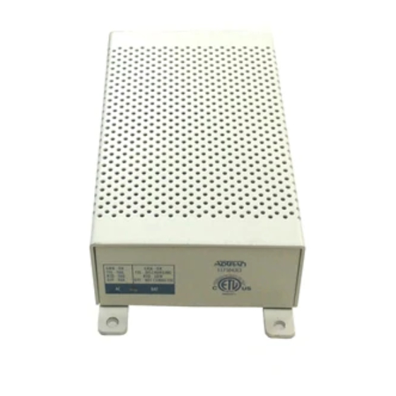
Figure 1. TA 750/850 Quad FXS ........................................ 1
Figure 2. FXO to FXS Deployment ................................... 2
Figure 3. CO Switch to FXS Deployment .......................... 2
Figure 4. Circuit Path ......................................................... 3
Figure 5. Connector Pin Assignments ................................ 4
Tables
Table 1. Telecommunications Codes ............................................. 3
Table 2. TA 750 Time Slot Assignments ....................................... 4
Table 3. Specifications ................................................................... 6
1. GENERAL
This practice provides installation and maintenance
procedures for the ADTRAN Total Access
(TA 750/850) Quad Foreign Exchange Station (FXS)
Access Module. Figure 1 is an illustration of the
Quad FXS Module. The Quad FXS is designed
specifically for the ADTRAN Total Access 750 and
850 chassis and is not used in any other product. The
unit is multifunctional and can be provisioned to
operate in any one of the following modes:
•
2-Wire Foreign Exchange Station (2FXS)
•
Dial Pulse Originate (DPO)
•
Tandem FXS Mode
•
Private Line Automatic Ringdown (PLAR)
Revision History
This document has been revised to include Windows
Hyperterminal and PASSWORD information.
Features
The features of the TA 750/850 Quad FXS, part
number 1175408L1, include:
•
Provides four individual analog voice
interfaces.
•
Automatic short loop provisioning feature.
µ-law encoding and decoding.
•
61175408L1-5C
27 March 00
Total Access
QUAD FXS Access Module
Installation and Maintenance
TM
750/850
Trademarks: Any brand names and product names included in this document are
Section 61175408L1-5, Issue 3
trademarks, registered trademarks, or trade names of their respective holders.
CLEI Code: SIC2WXOK_ _
TM
750/850
Figure 1. TA 750/850 Quad FXS
•
Supports ground start, loop start, and TR-08
signaling.
•
Long loop capability - 1200 ohms (nominal)
including telephone set (16 kfeet @ 24 AWG).
•
Hot Swappable.
•
V.90 Modem compliant.
•
Supports CLASS
TM
•
Transmit attenuation setting of 0 to -9 dB.
•
Receive attenuation setting of 0 to -9 dB.
•
Selectable 600Ω, 900Ω, 600Ω+2.16µF,
or 900Ω+2.16µF 2-wire VF interface.
•
Occupies a single slot in the TA 750 or TA 850
chassis.
•
UL 1950 compliant.
•
Extended temperature range of -40 to +65º C.
•
Call Forward Disconnect
•
Meets NEBS Level 3 reguirements
General Description
The Quad FXS access module is used in the
TA 750/850 platforms to provide analog voice
extension. The Quad FXS resides in the TA chassis
that is next or close to the customer's telephone and is
usually located on the customer premises. The unit
Section 61175408L1-5C
Issue 3, March 2000
1175408L1
features such as Caller ID.
1
Advertisement
Table of Contents

Subscribe to Our Youtube Channel
Related Manuals for ADTRAN Total Access 750


Summary of Contents for ADTRAN Total Access 750
-
Page 1: Table Of Contents
(16 kfeet @ 24 AWG). Quad FXS Module. The Quad FXS is designed • Hot Swappable. specifically for the ADTRAN Total Access 750 and • V.90 Modem compliant. 850 chassis and is not used in any other product. The •... -
Page 2: Installation
(2) this device must accept any interference intended to be installed in restricted access locations received, including interference that may cause and in the Total Access 750 /850 chassis only, and in undesired operation. equipment with a Type 'B' or 'E' installation code. -
Page 3: Figure 4. Circuit Path
Table 1. Telecommunications Codes Transmit Path (To Backplane) 0 to +9 dB Input TLP Tx Atten Point Code Input Output 0 dBm0 0 to -9 dB TLP0 Rx Atten 0 dBm0 0 to -9 dB TLP0 -9 to 0 dB Output TLP Receive Path (From Backplane) Point... -
Page 4: Operation
NOTE NOTE To ensure proper display background, select If the unit is inserted into a bank which has its VT 100 terminal emulation under timeslots allocated to the module assigned to SETTINGS. the DSX-1 or Nx56/64 port, the LEDs will sequence, indicating a problem. -
Page 5: Testing
TA 750 or TA 850 chassis. The test verifies proper operation of critical circuits. If the ADTRAN does not recommend that repairs be test is successful all four LEDs turn On in a performed in the field. Repair services are obtained by... -
Page 6: Warranty And Customer Service
Table 3. Specifications 8. WARRANTY AND CUSTOMER SERVICE ADTRAN will replace or repair this product within 10 years from the date of shipment if it does not meet its s t t published specifications or fails while in service (see:...
Need help?
Do you have a question about the Total Access 750 and is the answer not in the manual?
Questions and answers