
Related Manuals for Cabletron Systems CyberSWITCH CSX101


Summary of Contents for Cabletron Systems CyberSWITCH CSX101
- Page 1 CyberSWITCH 100 FAMILY INFORMATION LINE P/N 9031944-01 September 1997...
-
Page 3: Fcc Notice
Cabletron Systems reserves the right to make changes in specifications and other information contained in this document without prior notice. The reader should in all cases consult Cabletron Systems to determine whether any such changes have been made. The hardware, firmware, or software described in this manual is subject to change without notice. IN NO EVENT SHALL CABLETRON SYSTEMS BE LIABLE FOR ANY INCIDENTAL, INDIRECT, SPECIAL, OR CONSEQUENTIAL DAMAGES WHATSOEVER (INCLUDING BUT NOT LIMITED TO LOST PROFITS) ARISING OUT OF OR RELATED TO THIS MANUAL OR THE INFORMATION CONTAINED IN IT, EVEN IF CABLETRON SYSTEMS HAS BEEN... -
Page 4: Vcci Notice
Notice VCCI Notice CyberSWITCH 100 Advanced User Information... - Page 5 VCCI Notice This is a Class A product based on the standard of the Voluntary Control Council for Interference by Information Technology Equipment (VCCI). If this equipment is used in a domestic environment, radio disturbance may arise. When such trouble occurs, the user may be required to take corrective actions.
-
Page 6: United States Government Restricted Rights
Notice Exclusion of Warranty and Disclaimer of Liability EXCLUSION OF WARRANTY. Except as may be specifically provided by Cabletron in writing, Cabletron makes no warranty, expressed or implied, concerning the Program (including its documentation and media). CABLETRON DISCLAIMS ALL WARRANTIES, OTHER THAN THOSE SUPPLIED TO YOU BY CABLETRON IN WRITING, EITHER EXPRESSED OR IMPLIED, INCLUDING BUT NOT LIMITED TO IMPLIED WARRANTIES OF MERCHANTABILITY AND FITNESS FOR A PARTICULAR PURPOSE, WITH RESPECT TO THE PROGRAM, THE ACCOMPANYING WRITTEN MATERIALS, AND ANY ACCOMPANYING HARDWARE. -
Page 7: Table Of Contents
ISDN BRI Configurations... 3 SPIDs, Directory Numbers and Telephone Numbers... 4 Telephone Switch Parameters ... 5 CHAPTER 2 ABOUT THE CYBERSWITCH 100 ROUTER... 9 CyberSWITCH 100 Hardware... 10 ISDN WAN Connection ... 10 POTS Analog Telephone Connection ... 10 CyberSWITCH 100 Software Support ... 10 IEEE 802.3 Ethernet... - Page 8 Contents CHAPTER 3 PLANNING YOUR ROUTER’S CONFIGURATION ... 23 Configuration Process and Terminology ... 23 Custom Step-by-Step Configuration ... 23 Collect Network Information ... 23 Remote Connections ... 31 CHAPTER 4 CYBERSWITCH 100 HARDWARE FEATURES ... 39 Front Panel... 39 Rear Panel ...
-
Page 9: Preface
Apppendix B, Glossary, defines commonly used terms, and is located at the back of this guide. Preface Configuration, provides the information you need to order Router, describes the CSX100 family hardware Configuration, describes the router configuration process. Features, describes the front and rear panels of the... -
Page 10: Document Conventions
Preface Document Conventions The following conventions are used throughout this guide: Note symbol. Calls the reader’s attention to any item of information that may NOTE be of special importance. Tip symbol. Conveys helpful hints concerning procedures or actions. Caution symbol. Contains information essential to avoid damage to the equipment. -
Page 11: Getting Help
Getting Help If you need additional support related to this device, or if you have any questions, comments, or suggestions concerning this manual, contact Cabletron Systems Global Call Center: Phone Internet mail Login Password Modem setting For additional information about Cabletron Systems or our products, visit our World Wide Web site: http://www.cabletron.com/ For technical support, select Service and Support. - Page 12 Preface CyberSWITCH 100 Advanced User Information...
-
Page 13: Chapter 1 Isdn Line Ordering And Configuration
ISDN Line Ordering and Configuration This chapter provides ISDN BRI (Basic Rate Interface) line ordering and configuration information. It contains the following sections: • Arranging ISDN Service • Telephone Switch Support • ISDN BRI Line Configuration • SPIDs, Directory Numbers and Telephone Numbers •... -
Page 14: Telephone Switch Support
ISDN Line Ordering and Configuration Telephone Switch Support Your telephone company may offer a variety of ISDN switch types. You must contact your service provider and find out which type of ISDN service is available. The following switch types are currently supported by the CyberSWITCH 100 within the U.S.: •... -
Page 15: Isdn Bri Configurations
ISDN Line Ordering and Configuration In the U.S. and Canada, an NT1 Network Terminator is required to provide an interface between the CyberSWITCH 100 and the ISDN line. The NT1 offers conversion between the two-wire twisted pair (U-loop interface) used by telephone companies and the four-wire terminal equipment (S/T Interface) as well as line-testing capabilities. -
Page 16: Spids, Directory Numbers And Telephone Numbers
ISDN Line Ordering and Configuration SPIDs, Directory Numbers and Telephone Numbers The service provider gives you up to three sets of numbers for identifying the ISDN line and devices. You may be assigned none, one, or two Service Profile Identifier numbers (SPIDs) or Directory Numbers (DNs) depending on the service provider and country. -
Page 17: Telephone Switch Parameters
Telephone Switch Parameters Once you have contacted your service provider and learned the type of ISDN switch being used, refer to Tables 1 through 3. You must supply the appropriate provisioning information to the service provider to ensure proper configuration of the ISDN line. National ISDN (NI-1) is a specification released by Bellcore outlining a basic NOTE set of ISDN services for standardization by equipment vendors. - Page 18 ISDN Line Ordering and Configuration Table 2 AT&T 5ESS with Custom Software ISDN Switch Parameters Multipoint Terminal Type Display MTERM MAXB CHL ACT USR CSD CHL CSD Limit CA Pref Nail Up CyberSWITCH 100 Advanced User Information Value Circuit Switched Data & Voice Circuit Switched Data &...
- Page 19 Table 3 Northern Telecom DMS-100 ISDN Switch Parameters EKTS Ringing Indicator Release Key PVER MAXKEYS Nail Up ISDN Line Ordering and Configuration Value Circuit Switched Data & Voice Circuit Switched Data & Voice Signaling Only Dynamic None CyberSWITCH 100 Advanced User Information...
- Page 20 ISDN Line Ordering and Configuration CyberSWITCH 100 Advanced User Information...
-
Page 21: Chapter 2 About The Cyberswitch 100 Router
The CyberSWITCH 100 is a bridge/router providing remote Ethernet LAN connectivity via a single ISDN line for the small office or home office (SOHO). This multi-protocol router offers telecommuters and home and remote office workers high speed dial-up access to remote sites, such as the Internet and the enterprise network (see Figure 1). -
Page 22: Cyberswitch 100 Hardware
About the CyberSWITCH 100 Router CyberSWITCH 100 Hardware The CyberSWITCH 100 family (consisting of the CSX101, CSX103, CSX104, and CSX105) provides one Ethernet port and one ISDN Basic Rate Interface (BRI) port (with built-in S/T, or U interfaces). The CSX104 and CSX105 also support two analog device Plain Old Telephone Service (POTS) ports. -
Page 23: Ieee 802.3 Ethernet
PAP provides verification of passwords between routers using a 2-way handshake. One router (peer) sends its system name and password to the other router. Then the other router (known as the authenticator) checks the peer’s password against the configured remote router’s password and returns acknowledgment. -
Page 24: Isdn
512 Kbps (data rate, after decompression). A Network Terminator device (NT1) provides the interface between ISDN terminal (router) equipment and the ISDN service provider. In the U.S., the NT1 is provided by the customer;... -
Page 25: Bridging And Routing
The CyberSWITCH 100 can operate as a bridge, as a router, or as both (sometimes called a brouter). The CyberSWITCH 100 operates as a router for network protocols that are supported when routing is enabled. The router operates as a bridge when bridging is enabled. -
Page 26: Ip And Ipx Routing
CyberSWITCH 100 must be “seeded” with static IP routes so that it dials out to the appropriate remote router when IP traffic is targeted to networks and stations 14 CyberSWITCH 100 Advanced User Information... - Page 27 An IP route includes an IP address, subnet mask and metric. The metric is a number representing the perceived cost in reaching the remote network or station. After the link is established, RIP update packets are dynamically added to the routing table.
- Page 28 Local WAN IP address, unnumbered mode negotiation is not performed; i.e., the operating mode is numbered. If a Local WAN IP address is explicitly defined, the router will not, as a rule, accept another local address from the remote end. In numbered mode without an explicit Local WAN IP address, this address can be negotiated to a different value by the remote end.
- Page 29 CyberSWITCH 100 local Ethernet LAN connection. The ISDN WAN link to each remote router must have an assigned IPX network number. IPX Routes and IPX SAPs for each remote router are also required for the configuration process. Figure 6 shows the network layout for IPX routing.
- Page 30 The CyberSWITCH 100 SAP services table must be seeded statically so that the device can direct traffic to the appropriate remote router when a service is requested from a server beyond that remote router. After the link is established, SAP broadcast packets dynamically add to the target router services table.
- Page 31 Servers are identified with internal network numbers. This is a logical network number that identifies the individual server. For a local router to access a server beyond the remote router, you specify a route using the internal network number of a server. To seed the routing table to access a network segment, you specify the external network number of the LAN segment.
-
Page 32: Bridging And Routing Protocol Filtering
Bridge filtering allows a network administrator to control the flow of packets across the router. Bridge filtering can be used to “deny” or “allow” packets based on a “matched pattern” using a specified position and hexadecimal content within the packet. This enables restricting or forwarding of messages based on address, protocol or data content. -
Page 33: Pots Analog Line Interface
The CyberSWITCH 100 provides SNMP agent support and support for standard as well as Enterprise-Specific MIBs (Management Information Bases). SNMP is also used internally for configuration of the router. The active SNMP agent within the router accepts SNMP requests for status, statistics and configuration updates. Communication with the SNMP agent occurs over the LAN or WAN connection. - Page 34 About the CyberSWITCH 100 Router 22 CyberSWITCH 100 Advanced User Information...
-
Page 35: Chapter 3 Planning Your Router's Configuration
The following definitions and screen figures describe the data that you will have to enter in the various QuickSET Custom Step-by-Step Configuration screens. The location of all of the remote routers to which this device may connect are added to a database called the remote router database that resides in the CyberSWITCH 100. - Page 36 Planning Your Router’s Configuration Figure 7, below, shows the IP Address and Default Gateway screen from the Custom Step-by-Step QuickSET configuration. Enter an IP Address and a Subnet Mask for your IP Address and Default Gateway — CyberSWITCH. If your Internet Service Provider or network administrator has given you a Default Gateway address, enter it in the Default Gateway window.
- Page 37 Planning Your Router’s Configuration You must choose a CyberSWITCH Name CyberSWITCH Name and System Password — (System Name) for the CyberSWITCH 100 and the System Password, both of which will be used by remote sites to authenticate your CyberSWITCH 100.
- Page 38 Planning Your Router’s Configuration Figure 8 ISDN Information Screen Clicking the DHCP Settings button on the ISDN Information Screen will DHCP Settings — cause the DHCP Settings configuration panel to appear (see Figure 9 on the following page). This window lets you configure Dynamic Host Configuration Protocol for your CyberSWITCH.
- Page 39 Planning Your Router’s Configuration Figure 9 DHCP Settings Panel Enter the first and last IP Address of the Address Pool (series of consecutive IP Addresses) in the respective windows. Enter the Default Gateway address in the respective window. The Default gateway specifies an address that packets not on your local subnet will be sent to (normally the IP...
- Page 40 Planning Your Router’s Configuration Clicking the POTS Settings button on teh ISDN Information Screen will cause POTS Settings — the POTS Settings panel to appear. POTS (Plain Old Telephone Service) refers to the two POTS analog telephone interfaces on the CyberSWITCH 104 and 105 rear panel. These interfaces emulate central office voice services to control the analog lines.
- Page 41 You must subscribe to a service called Additional Call Offering, or ACO, for the voice call to be forwarded to the CyberSWITCH. The Preemption Rules are as follows: Automatic Preemption will automatically bring down a B channel CyberSWITCH 100 Advanced User Information 29 Planning Your Router’s Configuration...
- Page 42 Planning Your Router’s Configuration Use Automatic Preemption On — • All Calls = Automatic preemption applies for both outgoing and incoming calls. • Incoming Calls Only = Automatic preemption applies for incoming calls. • Outgoing Calls Only = Automatic preemption applies for outgoing calls.
-
Page 43: Remote Connections
You can enable or disable any remote by clicking the Enable Remote radio button on or off. You can disable Authentication by clicking the Disable Authentication checkbox. Planning Your Router’s Configuration You can use the scroll bar in the Remote Connections window to CyberSWITCH 100 Advanced User Information 31... - Page 44 Planning Your Router’s Configuration Use the Remote’s Password button to enter the password to a remote that Remote’s Password — you wish to communicate with. The User Account Info panel is where you enter an account name and User Account Info —...
- Page 45 Planning Your Router’s Configuration Bandwidth Threshold % is a value from 0% to 100%, representing a threshold at which the second B channel will be allocated to maximize data transmission. Bandwidth Management can be applied to both incoming and outgoing traffic. To apply Bandwidth Management to both incoming and outgoing traffic, click the Both checkbox.
- Page 46 Planning Your Router’s Configuration The Metric Number indicates the relative complexity (and cost) of the route in the data base. Lower Metric numbers indicate less complex routes, and will be given preference in establishng a connection. The range of the Metric parameter is from one to fifteen.
- Page 47 Planning Your Router’s Configuration Enter the External IPX Network Number in the appropriate External IPX Network Number — window. IPX Network Numbers are made up of four pairs of hexadecimal digits (1A2B3C4F is a typical IPX Network Number). The Hop Count window is where you enter the number (greater than one) of Hop Count —...
- Page 48 Planning Your Router’s Configuration Enter the External IPX Network Number in the appropriate External IPX Network Number — window. IPX Network Numbers are made up of four pairs of hexadecimal digits (1A2B3C4F is a typical IPX Network Number). The Hop Count window is where you enter the number (greater than one) of Hop Count —...
- Page 49 RIP Off = Disables the CyberSWITCH’s ability to detect and respond to any RIP packets. Click the Next button when you have finished, and the Save button to save your configuration data and reboot your CyberSWITCH. Planning Your Router’s Configuration CyberSWITCH 100 Advanced User Information 37...
- Page 50 Planning Your Router’s Configuration 38 CyberSWITCH 100 Advanced User Information...
-
Page 51: Chapter 4 Cyberswitch 100 Hardware Features
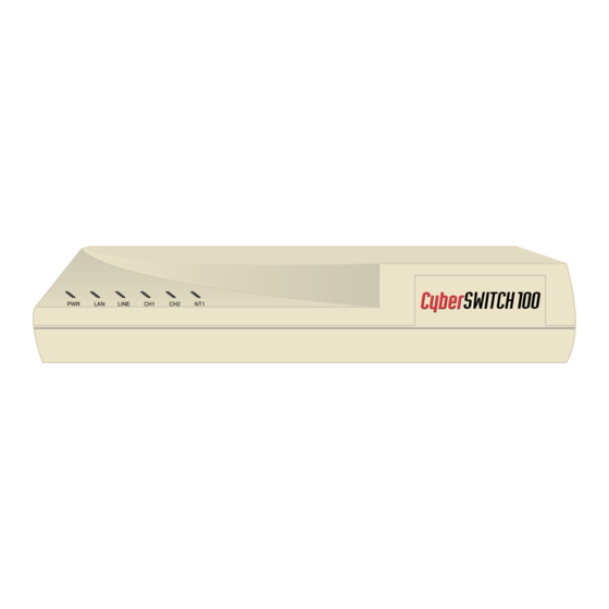
CyberSWITCH 100 Hardware Features Front Panel The front panel LEDs display the activity of the CyberSWITCH 100 Router. Figure 17 shows the location of the LEDs. Table 1 describes the LED functions. Table 2 describes the states of the ISDN LEDs (Line, CH1 and CH2). Table 3 describes the states of the NT1 LED (CSX103 and CSX105 models only). - Page 52 CyberSWITCH 100 Hardware Features Condition Error condition on S/T or U Interface SPIDs negotiation DSL idle (Standby) Dial/Answer Send/Receive Data Connected but Idle NT1 State Fast Blinking Slow Blinking 40 CyberSWITCH 100 Advanced User Information Table 5 ISDN LED States LINE OFF or Slow Blinking...
-
Page 53: Rear Panel
2A MAX. 50/60 Hz CSX101 100-120/200-240 VAC 2A MAX. 50/60 Hz The 10BASE-T Ethernet LAN interface. The router is connected to the Ethernet 10BASE-T — LAN with UTP Ethernet cable at this interface. Configuration switches that control software execution. See Switch information in CONFIG —... -
Page 54: Port Descriptions
CyberSWITCH 100 Hardware Features A port on the CSX101, CSX103 and CSX105. On the CSX101, the ISDN S/T is the ISDN S/T — only jack: it specifies the Terminal Equipment (TE)-configured S/T interface to external NT1 equipment. On the CSX103 and CSX105, a U jack is provided along with a built-in NT1. Additional ISDN TE equipment can be attached to this Network Termination (NT)-configured S/T jack. - Page 55 Table 8 ISDN Port Pin Number S/T (TE) TE (TE) Not Connected Not Connected Transmit Receive Receive Transmit Not Connected Not Connected Table 9 POTS Ports Pin Number CyberSWITCH 100 Hardware Features U-Loop S/T (NT) Interface (U.S.) Not Connected Not Connected Not Connected Not Connected Receive...
-
Page 56: Configuration Switches
S/T bus configuration and is not at the end of the bus. With both switches 1 and 2 in the DOWN (ON) position after the router has booted, the login password is overridden allowing a forgotten password to be re-entered. - Page 57 Disables terminators on S/T DOWN (default) Enables terminators on S/T N.A. No Function N.A. No Function UP (default) Normal Router operation mode DOWN Maintenance Mode UP (default) Automatic boot DOWN Manual boot CyberSWITCH 100 Advanced User Information 45 CyberSWITCH 100 Hardware Features...
- Page 58 CyberSWITCH 100 Hardware Features CSX105 100-120/200-240 VAC 2A MAX. 50/60 Hz CSX103 100-120/200-240 VAC 2A MAX. 50/60 Hz CSX101 100-120/200-240 VAC 2A MAX. 50/60 Hz Figure 19 CyberSWITCH 100 Configuration Switches 46 CyberSWITCH 100 Advanced User Information ISDN POTS POTS CONFIG 1 2 3 4 ISDN...
-
Page 59: Chapter 5 Troubleshooting
ISDN equipment that is operational, temporarily plug it into the wall jack to verify the ISDN line out to the service provider. ISDN NT1 LED IS FAST BLINKING • The router NT1 is having trouble negotiating the ISDN U interface layer 1 protocol with the central office. CyberSWITCH 100 Advanced User Information 47... -
Page 60: Investigating Software Configuration Problems
ISDN line is operational out to the service provider. ISDN LINE CHANNEL LED IS FAST BLINKING • The router is having trouble negotiating SPIDs and DNs with the central office. Investigating Software Configuration Problems Software problems usually occur when your software configuration contains incomplete or incorrect information. - Page 61 Change your login password to a new password. Store the configuration and reboot the router. If you have not reset Switch 1 and 2 UP and have rebooted, you will place the router in NOTE maintenance mode. Set Switch 1 and 2 UP and turn the power OFF and then ON.
-
Page 62: How To Obtain Technical Support
• Check that TCP/IP Routing is set on and is enabled at the remote end. • Check that the IP address of the LAN beyond the remote router is correct, as well as the associated subnet mask. • If the remote router WAN IP address and subnet mask are required, check that they have been specified correctly. -
Page 63: Getting Help
Before contacting Technical Support, gather the following information: • Description of the problem, onset, duration and affected components. • List of all CyberSWITCH 100 models, serial numbers and the date you purchased the products. • Level and success of the POST Test. •... - Page 64 Troubleshooting 52 CyberSWITCH 100 Advanced User Information...
-
Page 65: Appendix Ahardware Specifications
Hardware Specifications WAN Interface LAN Interface Other Interfaces Processor Width Height Depth Weight Power Supply Voltage Frequency Power Consumption Operating Temperature Humidity Table 12 Hardware Specifications One ISDN BRI (w/built-in S/T, or S/T and U interfaces) One Ethernet port, 10BASE-T (TPE RJ45) AC Power Connector Motorola MC68EN360/25 Mhz... - Page 66 Hardware Specifications 54 CyberSWITCH 100 Advanced User Information...
-
Page 67: Appendix Bglossary
Attachment Unit Interface. An IEEE 802.3 transceiver cable connecting the network AUI — device (such as a router) to the MAU (media access unit). Bandwidth on Demand — or closing multiple B channels) when the load in traffic increases or decreases. - Page 68 A telecommunications line between two service points leased from a Leased Line — communications carrier for private use, usually incurring a monthly service rate. Type of indicator lights on the panel of the router. LEDs (Light Emitting Diodes) — 56 CyberSWITCH 100 Advanced User Information...
- Page 69 Glossary A network connecting computers over a relatively small Local Area Network (LAN) — geographic area (usually within a single campus or building). Media Access Control layer/address defined by the IEEE 802.3 MAC Layer/Address — specification which defines media access including framing and error detection. Part of the OSI reference model Data Link layer.
- Page 70 Standard 4-wire connectors for telephone lines. Standard 8-wire connectors used for ISDN lines. RJ45 — RIP (Router Information Protocol) — information between routers to keep routing tables current. A Network layer function that determines the path for transmitting packets through a Routing —...
- Page 71 Glossary An extension of the Internet 32-bit addressing scheme that allows the Subnet Address — separation of physical or logical networks within the single network number assigned to an organization. TCP/IP entities outside this organization have no knowledge of the internal “subnetting.”...
- Page 72 Glossary 60 CyberSWITCH 100 Advanced User Information...
Need help?
Do you have a question about the CyberSWITCH CSX101 and is the answer not in the manual?
Questions and answers