
Related Manuals for Clenergy PV-ezRack ComT


Summary of Contents for Clenergy PV-ezRack ComT
- Page 1 ComT™ Code-Compliant Planning and Installation V2.0 Complying with AS/NZS1170.2:2011 AMDT 2-2012...
-
Page 2: Table Of Contents
Please also pay attention to any other relevant State or Federal regulations. Please check that you are using the latest version of the Installation Manual, which you can do by contacting Clenergy Australia via email on tech@clenergy.com.au, or contacting your local distributor in Australia. page of 17 Installation Guide_PV-ezRack ComT V2.0 (September 2020) -
Page 3: Planning
Local authorities will advise if this applies in your area. page of 17 Installation Guide_PV-ezRack ComT V2.0 (September 2020) Unit 1, 10 Duerdin St, Clayton VIC 3168, Australia Tel: +61 3 9239 8088 Fax: +61 3 9239 8024 E-mail: tech@clenergy.com.au www.clenergy.com.au... - Page 4 Terrain Category 4 (TC4) – Terrain with numerous larger, high (10m to 30m tall) and closely-spaced constructions buildings, such as large city centers and well-developed industrial complexes. If your installation site is not at TC 2, 2.5 or 3, please contact Clenergy to obtain a project specific engineering certificate to support your installation.
- Page 5 This document provides sufficient information for the PV-ezRack ComT™ system installation up to heights of 30 meters. If your installation site is more than 30 meters high please contact Clenergy to obtain project specific engineering certificate to support your installation.
-
Page 6: Tools And Components
ER-I-05 ECO Rail T50 Rail T110 Rail Tin Interface page of 17 Installation Guide_PV-ezRack ComT V2.0 (September 2020) Unit 1, 10 Duerdin St, Clayton VIC 3168, Australia Tel: +61 3 9239 8088 Fax: +61 3 9239 8024 E-mail: tech@clenergy.com.au www.clenergy.com.au... - Page 7 Z module with Bolt and Grounding Clip Grounding Lug Tray Washer page of 17 Installation Guide_PV-ezRack ComT V2.0 (September 2020) Unit 1, 10 Duerdin St, Clayton VIC 3168, Australia Tel: +61 3 9239 8088 Fax: +61 3 9239 8024 E-mail: tech@clenergy.com.au www.clenergy.com.au...
-
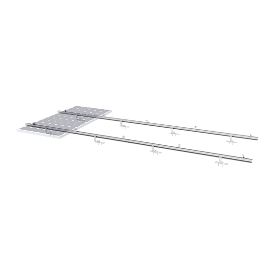
Page 8: System Overview
4.1 System Overview - Tin Interface with Eco Rail Spec. Item Part Name (mm) PV-ezRack ComT, Front Leg Assembly, 10°, with Z-Module and Grounding Pins PV-ezRack ComT, Rear Leg Assembly, 10°, with Z-Module and Grounding Pins PV-ezRack ECO Rail, length 4200mm L4200... - Page 9 (grease or 40# engine oil) to fasteners prior to tightening. 4.2.2 Safe Torques Please refer to safe torques defined throughoutthis guide. If power tools are required, Clenergy recommends the use of low speed only. High speed and impact drivers increase the risk of bolt galling (deadlock).
-
Page 10: Installation Instruction
In the case that any on-site modification or alteration of the system is neededplease provide marked up drawings/sketches for Clenergy’s review prior to modification for comment and approval. - Page 11 Please follow the steps below. 5.2.1 Based on the rib spacing of metal roof sheet, mark out the positions of self-tapping screws (Clenergy 240 mm long MT rail section is equipped with two Buildex 14-11 x 70 Hex Head Zips screws) on the MT-Rail...
- Page 12 Figure 9 and 10. Recommended torques: M8 Bolt:16-20N·m. Figure 9 Figure 10 page of 17 Installation Guide_PV-ezRack ComT V2.0 (September 2020) Unit 1, 10 Duerdin St, Clayton VIC 3168, Australia Tel: +61 3 9239 8088 Fax: +61 3 9239 8024 E-mail: tech@clenergy.com.au www.clenergy.com.au...
- Page 13 The Front and Rear Leg are complete as shown in Figure 13. Note: for the Rear Leg installation, either use Clenergy provided 6mm ball head driving socket (55 mm long) or normal Hexagonal head driving socket and extension to fasten bolts.
- Page 14 Figure 16. Leave z module untighten. Figure 16 page of 17 Installation Guide_PV-ezRack ComT V2.0 (September 2020) Unit 1, 10 Duerdin St, Clayton VIC 3168, Australia Tel: +61 3 9239 8088 Fax: +61 3 9239 8024 E-mail: tech@clenergy.com.au www.clenergy.com.au...
- Page 15 Figure 19. Figure 18 Figure 19 Figure 20 page of 17 Installation Guide_PV-ezRack ComT V2.0 (September 2020) Unit 1, 10 Duerdin St, Clayton VIC 3168, Australia Tel: +61 3 9239 8088 Fax: +61 3 9239 8024 E-mail: tech@clenergy.com.au www.clenergy.com.au...
- Page 16 Front and Rear Legs, and PV modules. Figure 24 page of 17 Installation Guide_PV-ezRack ComT V2.0 (September 2020) Unit 1, 10 Duerdin St, Clayton VIC 3168, Australia Tel: +61 3 9239 8088 Fax: +61 3 9239 8024 E-mail: tech@clenergy.com.au www.clenergy.com.au...
- Page 17 Rail as shown in the figure 26. Figure 26 page of 17 Installation Guide_PV-ezRack ComT V2.0 (September 2020) Unit 1, 10 Duerdin St, Clayton VIC 3168, Australia Tel: +61 3 9239 8088 Fax: +61 3 9239 8024 E-mail: tech@clenergy.com.au www.clenergy.com.au...
-
Page 18: Certification Letter And Spacing
Certification Letter and Interface Spacing Table page of 17 Installation Guide_PV-ezRack ComT V2.0 (September 2020) Unit 1, 10 Duerdin St, Clayton VIC 3168, Australia Tel: +61 3 9239 8088 Fax: +61 3 9239 8024 E-mail: tech@clenergy.com.au www.clenergy.com.au... - Page 19 07 July 2020 Clenergy Australia 1/10 Duerdin Street Clayton, VIC 3168 CERTIFICATION LETTER Clenergy PV ez‐Rack Commercial Tilt Certification – TC2, 2.5, 3 – Wind Region A, B, C, D. Internal REF: 00150‐REVB. MW Engineering Melbourne, being Structural Engineers within the meaning of Australian regulations, have calculated the maximum spacings for the PV ez‐Rack rail system for the following conditions: ‐ Wind Loads to AS 1170.2‐2011 AMDT 4‐2016 o Wind Terrain Category 2, 2.5 and 3 o Wind average recurrence of 500 years o Wind Region A, B, C, D ‐ Solar panel length up to 2.2 m ...
-
Page 20: Table
MW Engineering Melbourne constitutes an infringement in copyright. Limitation: This report has been prepared for the exclusive use of Clenergy Australia, and is subject to and issued in connection with the provisions of the agreement between MW Engineering Melbourne and Clenergy Australia. - Page 21 REF: 00150 Client: Clenergy Australia Project: PV ez-Rack Commercial Tilt Spacing table Australian Standards AS/NZS 1170.0:2002 (R2016) General Principles AS/NZS 1170.1:2002 (R2016) Imposed loadings AS/NZS 1170.2:2011 (R2016) Wind Loadings AS/NZS 1252.2:2016 Bolting AS/NZS 1664.1:1997-Amdt 1:1999 Aluminium Wind Terrain Category: 2, 2.5 &...
- Page 22 PV ez-Rack Commercial Tilt spacing Table 1.1 Type of Rail ER-R-ECO (ECO Rail) and all other ECO rails Type of Interface ER-I-05 (Tin Interface) Solar Panel Dimension 2 m x 1 m Purlin Thickness 1.9 mm Roof Angle - 0°...
- Page 23 PV ez-Rack Commercial Tilt spacing Table 1.2 Type of Rail ER-R-ECO (ECO Rail) and all other ECO rails Type of Interface ER-I-05 (Tin Interface) Solar Panel Dimension 2 m x 1 m Purlin Thickness 1.9 mm Roof Angle - 10°...
- Page 24 PV ez-Rack Commercial Tilt spacing Table 1.3 Type of Rail ER-R-ECO (ECO Rail) and all other ECO rails Type of Interface ER-I-05 (Tin Interface) Solar Panel Dimension 2 m x 1 m Purlin Thickness 1.9 mm Roof Angle - 20°...
- Page 25 PV ez-Rack Commercial Tilt spacing Table 2.1 Type of Rail ER-R-T50 Type of Interface S-MT/240 (MT – Rail support) Solar Panel Dimension 2 m x 1 m Purlin Thickness 1.9 mm Roof Angle - 0° < α < 10° BUILDING <...
- Page 26 PV ez-Rack Commercial Tilt spacing Table 2.1 Type of Rail ER-R-T50 Type of Interface S-MT/240 (MT – Rail support) Solar Panel Dimension 2 m x 1 m Purlin Thickness 1.9 mm Roof Angle - 10° < α < 20° BUILDING <...
- Page 27 PV ez-Rack Commercial Tilt spacing Table 2.3 Type of Rail ER-R-T50 Type of Interface S-MT/240 (MT – Rail support) Solar Panel Dimension 2 m x 1 m Purlin Thickness 1.9 mm Roof Angle - 20° < α < 30° BUILDING <...
- Page 28 PV ez-Rack Commercial Tilt spacing Table 3.1 Type of Rail ER-R-T110 Type of Interface S-MT/240 (MT – Rail support) Solar Panel Dimension 2 m x 1 m Purlin Thickness 1.9 mm Roof Angle - 0° < α < 10° BUILDING <...
- Page 29 PV ez-Rack Commercial Tilt spacing Table 3.2 Type of Rail ER-R-T110 Type of Interface S-MT/240 (MT – Rail support) Solar Panel Dimension 2 m x 1 m Purlin Thickness 1.9 mm Roof Angle - 10° < α < 20° BUILDING <...
- Page 30 PV ez-Rack Commercial Tilt spacing Table 3.3 Type of Rail ER-R-T110 Type of Interface S-MT/240 (MT – Rail support) Solar Panel Dimension 2 m x 1 m Purlin Thickness 1.9 mm Roof Angle - 20° < α < 30° BUILDING <...
- Page 31 Note 3. This Engineering Document was designed to cater for most common installation scenarios however, it does not cater for all of them. Contact Clenergy if you are unable to comply with any of the installation specifications listed on this document.
- Page 32 Components Part No. Description PV-ezRack Splice for T50 Splice ER-SP-T50 rail T110 Rail ER-R-T110/XXXX T110 Rail PV-ezRack Splice for T110 Slice ER-SP-T110 rail MT Rail Section S-MT/XXXX MT support Rail clamp for T-rail with Rail Clamp ER-RC-T/DM diamond module Rail clamp for T-rail with Z...
- Page 33 (R2016). Note 6. The installed frame must comply with the clamping zone of the PV Panel. Note 7. Capacities checked and compared against testing data from Clenergy Australia and MTS (NATA certified). Note 8. Maximum permitted rail overhang of 40%.
- Page 34 Clenergy Mounting System. Note 11. All components from Clenergy must be installed according to manufacturer's specification and the instructions shown in the relevant installation manual. Please check the Clenergy Australia website or contact them for access to the most recent installation manuals.
- Page 35 Note 20. Fixing spacing to be reduced to timber purlins as per below: Batten type 25 mm 30 mm 35 mm Reduction of 55% Reduction of 45% Reduction of 40% Timber F7 Spacings remain Decrease of 15% Increase of 15% Timber F17 the same...
- Page 36 Roof Pitch < 10° Roof Pitch > 10° July 2020 ...
- Page 37 Flat/Mono – Slope Roof < 10° Flat/Mono – Slope Roof > 10° July 2020 ...
- Page 38 Clenergy Philippines 145 Yakal St., San Antonio village, Makati City, Philippines Tel: +63 977 8407240 Worldwide Network E-mail: sales_ph@clenergy.com www.clenergy.ph Germany Japan South Korea China Thailand Philippines 10 Year Vietnam Warranty* Singapore Clenergy Installation Guide PV-ezRack ComT (September 2020) Australia...
Need help?
Do you have a question about the PV-ezRack ComT and is the answer not in the manual?
Questions and answers