
Subscribe to Our Youtube Channel
Related Manuals for Clenergy PV-ezRACK ComT


Summary of Contents for Clenergy PV-ezRACK ComT
- Page 1 ComT Code-Compliant Planning and Installation V2.0 Complying with AS/NZS1170.2:2011 AMDT 2-2012 Last Updated - Mar. 2022...
-
Page 2: Table Of Contents
This may occur between latest version of the Installation Manual, which you can structures and the building and also between do by contacting Clenergy Australia via email on structures, fasteners and PV modules, as detailed in tech@clenergy.com.au, or contacting your AS/NZS 5033: 2021. -
Page 3: Planning
Installation Guide / ComT Planning Determine the wind region of your installation site Region Definition Wind regions are pre-defined for the whole of Australia by the Australian Standard 1170.2. The Wind Region is an independent factor of surrounding topography or buildings. •... - Page 4 Terrain Category 4 (TC4) – Terrain with numerous larger, high (10m to 30m tall) and closely-spaced constructions buildings, such as large city centers and well-developed industrial complexes. If your installation site is not at TC 2, 2.5 or 3, please contact Clenergy to obtain a project specific engineering certificate to support your installation.
- Page 5 Installation Guide / ComT Determine System Tilt Angle The PV-ezRack® ComT system is fixed 10° tilt system. Determine Roof slope The PV-ezRack® ComT system can be used for roof slopes up to 30°. Please verify that the Installation site roof slope is between 0°...
-
Page 6: Tools And Components
M8 bolt) 6mm Ball Head Open Spanner, 12" long Driving Driving Socket – 14mm Socket Extension 55 mm long (optional) (provided by the Clenergy) Components FL-COMT/Z/G/10 RL-COMT/Z/G/10 ER-RC-T/DM S-MT/240 ER-R-ECO Front Leg Assembly, Rear Leg Assembly, Rail Clamp for T-Rail,... - Page 7 Installation Guide / ComT Components ER-I-25 EZ-CT-40/40/2560 CO-MT/855 EZ-Z-STBW EZ-GC-ST Tin Interface with MT-rail Cable Tray Cover for MT-rail Z module with Bolt Grounding Clip Curved Base for Cable Tray and Washer Corrugated Roof EZ-GL-ST Grounding Lug - Tools and Components - Code-Compliant Planning and Installation V2.0 - Complying with AS/NZS1170.2:2011 AMDT 2-2012...
-
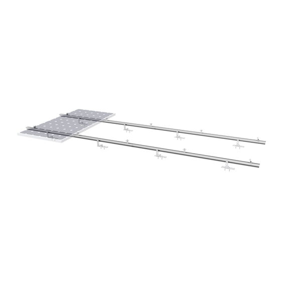
Page 8: System Overview
Tin Interface with Eco Rail Item Material Spec.(mm) PV-ezRack ComT, Front Leg Assembly, 10°, with Z-Module and Grounding Pins PV-ezRack ComT, Rear Leg Assembly, 10°, with Z-Module and Grounding Pins PV-ezRack ECO Rail, length 4200mm L4200 PV-ezRack SolarRoof ,Tin Interface... - Page 9 (grease or 40# engine oil) to fasteners prior to tightening. Safe Torques Please refer to safe torques defined throughoutthis guide. If power tools are required, Clenergy recommends the use of low speed only. High speed and impact drivers increase the risk of bolt galling (deadlock). If deadlock occurs and you need to cut fasteners, please make sure that there is no load on the fastener before you cut it.
-
Page 10: Installation Instruction
1) Fix the Tin Interface on the metal purlin with a self-tapping screw (Clenergy Tin interface is equipped with one Buildex 14-11 x 70 Hex Head Zips screw) according to the installation plan. Ensure that the Tin Interface in the front and rear or left and right directions are aligned using string as shown in Figure 1. - Page 11 1) Based on the rib spacing of metal roof sheet, mark out the positions of self-tapping screws (Clenergy 240 mm long MT rail section is equipped with two Buildex 14-11 x 70 Hex Head Zips screws) on the MT-...
- Page 12 Installation Guide / ComT 4) If the T Rail is not long enough, please apply Splice for T Rail to connect two T Rails together. Insert half of Splice into T Rail and fasten with two sets of Self-tapping screws in each side of T Rail, and then insert the other Splice into T Rail and fasten with Self-tapping screws as shown in Figure 8.
- Page 13 The Front and Rear Leg are complete as shown in Figure 13. Note: for the Rear Leg installation, either use Clenergy provided 6mm ball head driving socket (55 mm long) or normal Hexagonal head driving socket and extension to fasten bolts.
- Page 14 Installation Guide / ComT 4. MT-rail Cable Tray Installation (optional) The installation instruction below is to take ECO Rail as an example, the installation instruction of T-rail is the similar. 1) According to the installation plan and MT-rail cable tray load vs. span data below, mark fixing positions of Cable Tray on top of ECO rail.
- Page 15 Installation Guide / ComT 5) Fasten all M8 bolts with the recommended toque of 15- 17N·m. Note: Check the electrical resistance between ECO rail and cable tray to ensure the bonding is made. Figure 18 6) Align and click MT-rail cable tray cover in as showed in Figure 19. Figure 19 Figure 20 - Installation Instructions -...
- Page 16 Installation Guide / ComT 5. PV Module Installation 1) Place the PV Modules on the Front and Rear Leg as shown Figure 21. The outside edge of the frame of the PV Modules must overlap the marking lines on the Front and Rear Legs as shown in Figure 22.
- Page 17 Installation Guide / ComT 6. Grounding System Installation Apply one pre-assembled Grounding Lug per Rail. Slide the Grounding Lug into to the rail channel and fasten the bolt M8*25 with 16~20 N·m. Strip earthing cable (the maximum size is 10 mm2) and insert the conductor into the provided copper tube.
-
Page 18: Certification
Installation Guide / ComT Certification - Certification - Code-Compliant Planning and Installation V2.0 - Complying with AS/NZS1170.2:2011 AMDT 2-2012... - Page 19 Installation Guide / ComT - Certification - Code-Compliant Planning and Installation V2.0 - Complying with AS/NZS1170.2:2011 AMDT 2-2012...
- Page 20 Installation Guide / ComT Code-Compliant Planning and Installation V2.0 - Complying with AS/NZS1170.2:2011 AMDT 2-2012...
- Page 21 Installation Guide / ComT Code-Compliant Planning and Installation V2.0 - Complying with AS/NZS1170.2:2011 AMDT 2-2012...
- Page 22 Installation Guide / ComT Code-Compliant Planning and Installation V2.0 - Complying with AS/NZS1170.2:2011 AMDT 2-2012...
- Page 23 Installation Guide / ComT Code-Compliant Planning and Installation V2.0 - Complying with AS/NZS1170.2:2011 AMDT 2-2012...
- Page 24 Installation Guide / ComT Code-Compliant Planning and Installation V2.0 - Complying with AS/NZS1170.2:2011 AMDT 2-2012...
- Page 25 Installation Guide / ComT Code-Compliant Planning and Installation V2.0 - Complying with AS/NZS1170.2:2011 AMDT 2-2012...
- Page 26 Installation Guide / ComT Code-Compliant Planning and Installation V2.0 - Complying with AS/NZS1170.2:2011 AMDT 2-2012...
- Page 27 Installation Guide / ComT Code-Compliant Planning and Installation V2.0 - Complying with AS/NZS1170.2:2011 AMDT 2-2012...
- Page 28 Installation Guide / ComT Code-Compliant Planning and Installation V2.0 - Complying with AS/NZS1170.2:2011 AMDT 2-2012...
- Page 29 Installation Guide / ComT Code-Compliant Planning and Installation V2.0 - Complying with AS/NZS1170.2:2011 AMDT 2-2012...
- Page 30 Installation Guide / ComT Code-Compliant Planning and Installation V2.0 - Complying with AS/NZS1170.2:2011 AMDT 2-2012...
- Page 31 Installation Guide / ComT Code-Compliant Planning and Installation V2.0 - Complying with AS/NZS1170.2:2011 AMDT 2-2012...
- Page 32 Installation Guide / ComT Code-Compliant Planning and Installation V2.0 - Complying with AS/NZS1170.2:2011 AMDT 2-2012...
- Page 33 Installation Guide / ComT Code-Compliant Planning and Installation V2.0 - Complying with AS/NZS1170.2:2011 AMDT 2-2012...
- Page 34 Installation Guide / ComT Code-Compliant Planning and Installation V2.0 - Complying with AS/NZS1170.2:2011 AMDT 2-2012...
- Page 35 Installation Guide / ComT Code-Compliant Planning and Installation V2.0 - Complying with AS/NZS1170.2:2011 AMDT 2-2012...
- Page 36 Installation Guide / ComT - Certification - Code-Compliant Planning and Installation V2.0 - Complying with AS/NZS1170.2:2011 AMDT 2-2012...
- Page 37 Clenergy 1/10 Duerdin St Phone: +61 3 9239 8088 Clayton VIC 2168 Email: sales@clenergy.com.au Australia Web: www.clenergy.com.au @ClenergyGlobal / @ClenergyClub / ClenergyAUS @Clenergy @ClenergyClub @Clenergy_global @Clenergy A Clenergy Technologies Company...
Need help?
Do you have a question about the PV-ezRACK ComT and is the answer not in the manual?
Questions and answers