
Related Manuals for Blizzard Lighting TOURnado IP BAY


Summary of Contents for Blizzard Lighting TOURnado IP BAY
- Page 1 TOURnado™ IP BAY Blizzard Lighting, LLC www.blizzardlighting.com Waukesha, WI USA Copyright (c) 2015...
-
Page 2: Table Of Contents
Summary ............................... 3 Safety Instruction ............................4 Outside Size Picture ..................Error! Bookmark not defined. Main Function ............................... 5 DMX Control Function ..........................6 Display Operation instruction ........................9 DMX ADDRESS SETTING ........................11 STATIC SETTING ..........................12 DMX signal selection setting ......................12 Wireless set ............................ -
Page 3: Summary
Summary Summary Thank you for purchasing our TOURNADO™ IP BAY. Please read these instructions carefully before operating the fixture to avoid any possible damages or accidents causes by misusage. Product introduction The TOURNADO™ IP BAY fixtures feature 12x high output 5-in-1 RGBW+UV LEDs, and a highly cast aluminum housing durable . -
Page 4: Safety Instruction
2. Safety Instruction Safety Notes ! Enquire the skilled people before any repair; ! Always make sure disconnect from the power source before setting up, serving and moving;. ! Avoid direct eye exposure to the fixture when it is on; ... -
Page 5: Main Function
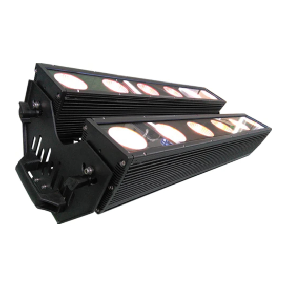
3. Dimensions 4. Main Function Input voltage: AC 100V-264V/47-63HZ Consume:300W Lamp Type:25W LED 5-in-1 R、G、B、UV、W (12PCS) Life span: 50000~100000hours PWM Dimmer:1500HZ(16666 grades) Control Signal:DMX512 Control mode:stand alone/master/slaver Channel:16CH、11CH、10CH、11CH.、6CH、5CH Function Effect: dimmer, strobe, gradual change... -
Page 6: Dmx Control Function
Touch buttons, automatic lock key Built-in temperature control measurement function, when LED work overheated, intelligent reduce LED output power, current power output and temperature can be viewed Cooling mode: Natural Convection Anti-electricity intension:1.5KV Insulation Resistance:>2MΩ ... - Page 7 171-210 Opening pulse(slow to fast) 211-250 Closing pulse(slow to fast) 251-255 No strobe No effect 6-10 CT01(Call custom color in menu settint) 11-15 CT02 16-20 CT03 21-25 CT04 26-30 CT05 31-35 CT06 36-40 CT07 41-45 CT08 46-50 CT09 51-55 CT10 56-60 AUTO 1 61-65...
- Page 8 201-205 AUTO 30 206-210 AUTO 31 211-215 AUTO 32 216-220 AUTO 33 221-225 CHASE1 226-230 CHASE2 231-235 CHASE3 236-255 Reserved Auto CH14 0-255 speed,fast->slow,(AT01-AT05:0-255S,AT 06-AT33:0-25.5S) Virtual colour wheel 0-10 No effect Blue (Blue=full, Red+Green+White=0)(step) Red=0, Green->up,Blue =full, 12-50 White=0(proportional) Light Blue (Red=0, Green=full, Blue =full, White=0)(step) Red=0, Green=full, Blue->down, 52-90...
-
Page 9: Display Operation Instruction
31-40 Inverse square law curve 41-50 S-curve 51-60 Linear curve and smooth 61-70 Square law curve and smooth 71-80 Inverse square law curve and smooth 81-90 S-curve and smooth Use the dimmer mode which menu had set 91-255 6. Display Operation instruction ... - Page 10 0-255 * 0-255 * SHUT 0-255 * SIGN(DMX signal SET(Set) 2.4G(wirelsee)/CABL(Cable) selection) WIRE(Wireless set) REST(reset) YES/NO CAL(Calibration) 0-255 0-255 0-255 0-255 0-255 YES/NO CHMD(Channel 16CH mode) 11CH 10CH 11CH. LIN(linear)/SQR(square law)/ISQR(inverse square law)/SCUR(S-curve)/LIN.(linear DIM(Dimming smooth)/SQR.(square law mode) smooth)/ISQR.(inverse square law smooth)/SCUR.(S-curve smooth) DISY(Display set) ON(Permanent on)
-
Page 11: Dmx Address Setting
CHS2(Chase 2) RUN* CHS3(Chase 3) RUN* PROG CHS1(Chase 1) SC01(Scene 1) 0-255 (Program) 0-255 0-255 0-255 0-255 0-255 0-255 0-255 0-255 0-255 SHUT 0-255 AUTO NONE,AT01-AT33 ATSP 0-255(S) TIME 0-255(S) WAIT 0-25.5(S) YES/NO SC25(Scene 25)25 CHS3(Chase 3) INFO SOFT(Software Vx.x (Information) version) TEM1(Temperature1) -
Page 12: Static Setting
3) Press the【ENTER】button to escape and save. 6.2 STATIC SETTING 1) Press the【ENTER】button in 【STAT】menu, then enter to the static setting. 2) Press the【UP/DOWN】 button to select 【RED1】,【GREEN1】,【BLUE1】...【WHITE2】and【SHUT 】. 3) Press the【UP/DOWN】button to set up the【0-255】numerical value. 4) Press the【ENTER】button to escape and save. 6.3 DMX signal selection setting 1) Press the【ENTER】button in【SIGN】menu, then enter to the DMX signal selection setting. -
Page 13: Channel Mode Setting
Illustrations: When pressing the【YES】button which means valid on the【USE】interface, the actual output value of RED,GREEN,BLUE,AMBER,WHITEis output in accordance with the percentage which the color cast calibration value divides 255. 6.7 CHANNEL MODE SETTING 1) Press the【ENTER】button in 【CHMD】menu, then enter to the channel mode setting. 2) Press the【UP/DOWN】button to select【16CH】,【11CH】,【10CH】,【11CH.】,【6CH】,【5CH 】... -
Page 14: Auto Run, Self-Program Run
2) Press the【UP/DOWN】button to select【1-255】numerical value. 3) Press the【ENTER】button to escape and save. 6.11 AUTO RUN, SELF-PROGRAM RUN 1)Press the【ENTER】button in【AUTO】menu, then enter to the auto run,self-program run. 2)Press the【UP/DOWN】button to select【AT01】…【AT33】,【SPEED】…【CHASE03】 3)Press the【ENTER】button to start running. 6.12 EDIT SELF-PROGRAM 1) Press the【ENTER】button in【PROG】menu, then enter to the edit self-program. -
Page 15: Prog】Self-Programming Parameter Reset
2) Press the【UP/DOWN】button to select【YES】. 3) Press the【ENTER】button to escape and save. Illustrations: “ADDR” “CTST” and “PROG” are not reset, the others reset to the underlined value of the word. 【 【 【 【 PROG】 】 】 】 SELF-PROGRAMMING PARAMETER RESET 6.15 1) Press the【ENTER】button in【PR L】menu, then enter to the【PROG】self-programming parameter reset. -
Page 16: Operating Control Instruction
Working in normal mode, indicator has 7 colors for option, when light and transmitter indicator are in the same color, can receive and transmit data. User-defined function is not available. Notice: compatible Sweden DMX mode in this lights has complete data for sending and receiving, but transmit function is not available here. -
Page 17: Connecting Picture
resistance120Ω ( 1/4W ) at connecting below: The Conversion between 3 pin and 5 pin XLR If the output cable of DMX512 controller is the 5PIN, please use 1pc 5PIN to 3PIN cable 10. Connecting picture Light connecting picture: ... -
Page 18: Trouble Shooting
11. Trouble Shooting PROBLEM REASON AND ACTION Check the power connection is correct or not. Please detect the voltage. The lightin g can’t be Power supply is damaged or incorrect connected. Call a started normally qualified personnel to fix it. ...
Need help?
Do you have a question about the TOURnado IP BAY and is the answer not in the manual?
Questions and answers