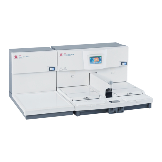
Sakura Tissue-Tek TEC 6 Operating Manua
Embedding module
Hide thumbs
Also See for Tissue-Tek TEC 6:
- Operating manual (54 pages) ,
- Quick reference manual (4 pages)

Related Manuals for Sakura Tissue-Tek TEC 6


Summary of Contents for Sakura Tissue-Tek TEC 6
- Page 1 Tissue-Tek ® ™ Embedding Module Operating Manual Part Number M01-021E-02 Revision Letter Released 2019-11-07...
- Page 2 The brand names of products that have been registered or trademarked by and are owned by Sakura Finetek USA, Inc., Sakura Finetek Japan Co., Ltd., and Sakura Finetek Europe B.V. appear here: Sakura Tissue-Tek © 2018 Sakura Finetek Japan Co., Ltd.
-
Page 3: Table Of Contents
Table of contents 1. Introduction Intended Use …………………………………………………………7 Safety Precautions …………………………………………………8 Precautions for Use ……………………………………………… 14 Overview of the Instrument …………………………………… 19 1.4.1 Instrument Configuration ……………………………… 19 1.4.2 Specifications …………………………………………… 20 Accessories ……………………………………………………… 21 1.5.1 Standard Accessories (Embedding Module) ………… 21 1.5.2 Optional Accessories (Embedding Module) …………... - Page 4 3.2.4 Turning On/Off the Work Light ………………………… 68 3.2.5 Continuing Embedding after the End Time of Auto Operation ………………………………………………… 69 3.2.6 Ending the Auto Operation before the End Time …… 70 Handling of Standard and Optional Accessories …………… 71 3.3.1 Wrist Rest ………………………………………………… 71 3.3.2 Wrist Rest Cushion ………………………………………...
- Page 5 Table of contents...
-
Page 6: Introduction
1. Introduction... -
Page 7: Intended Use
1. Introduction 1.1 Intended Use ® ™ The Tissue-Tek 6 Embedding Module (hereinafter referred to “the instrument”) is intended to embed processed human or animal tissue in paraffin by melting solid paraffin and dispensing molten paraffin. This instrument is used to facilitate as part of steps to produce tissue specimens for histological studies and tests conducted in the fields of pathology, anatomy, clinical pathology, etc. -
Page 8: Safety Precautions
1.2 Safety Precautions Designate the "Instrument Control Manager." • Operation of the instrument requires expert knowledge of the target application, method of use, and so on. Therefore, to use the instrument correctly and safely, designate an "Instrument Control Manager." • When the instrument is delivered, the Instrument Control Manager should receive explanation on the handling of the instrument directly from the staff trained in the instrument or distributor. - Page 9 1. Introduction The symbols used on the labels attached to the instrument are explained. The labels bearing one of the following symbols provide particularly important information you must know in order to ensure safety of the operator, improve work efficiency and protect the instrument from damage. Be sure to check these labels and understand the specified instructions before commencing your work A label bearing this symbol specifies an action that must be taken.
- Page 10 Do not forcibly bend, pull, twist or bundle the power cord. If the damaged power cord is used, fire or electric shock may occur. If the power cord or power plug has scratches or other abnormalities, contact the Sakura instrument distributor or representative.
- Page 11 1. Introduction • Check the power cord and electrical outlet for damage and accumulated dust and/or paraffin periodically. Failure to do so may cause fire depending on the condition. • Keep the instrument with the optional magnifying lens away from direct sunlight exposure.
- Page 12 Perform periodic inspection of the instrument every 6 months. Perform periodic inspection of the instrument every 6 months to ensure safe use of the instrument and maintain its performance. For details on periodic inspection, contact the Sakura instrument distributor or representative. •...
- Page 13 1. Introduction • Precautions when installing the instrument (Installation) Do not put down the instrument in an unstable place or on a floor or surface with insufficient strength. • Stay away from the instrument during earthquake. The instrument may fall over and cause injury. •...
-
Page 14: Precautions For Use
1.3 Precautions for Use CAUTIONS: • Precautions when using the instrument (Keep fire away) Do not bring fire sources close to the instrument. The paraffin in the instrument may ignite. • Precautions when moving the instrument Do not move the instrument while molten paraffin is inside. Before moving the instrument, unplug the power cord and remove the paraffin inside the instrument or wait for it to cool and solidify. - Page 15 1. Introduction • Precautions when removing the wrist rests An attempt to remove the wrist rest forcedly may result in injuring your fingertip. Use the scraper. • Precautions when cleaning (Caution for high temperature) Unless otherwise instructed in this document, turn off the power before cleaning the heated areas.
- Page 16 Precautions for Prevention of Failures • When cleaning the instrument, do not use any organic solvents (xylene). If any organic solvents flow into the paraffin line between the paraffin chamber and the dispenser, the internal parts may degrade or deform, resulting in failure. Also, the coatings and materials on/of the exterior panels, control panel display, etc., may deteriorate.
- Page 17 1. Introduction • Do not extend the power cord using a different cord, etc. Connect the instrument power cord directly to an electrical outlet instead of extending it using a different cord, etc. If the power cord is extended and connected, the supply voltage may drop and the compressor may stop working.
- Page 18 Precautions for Proper Embedding • Make sure the tissues, paraffin, cassettes and base molds are of the same temperature. During embedding, set the instrument temperature so that the tissues, paraffin, cassettes and base molds can be kept at the same, appropriate temperature as much as possible.
-
Page 19: Overview Of The Instrument
1. Introduction 1.4 Overview of the Instrument 1.4.1 Instrument Configuration The instrument comprises: A storage area where the paraffin-infiltrated tissues (specimens), base molds and molten paraffin used for embedding are kept at appropriate temperatures; A hot plate that performs a key part of embedding: A cold spot used for positioning and orienting the tissue;... -
Page 20: Specifications
1.4.2 Specifications ® ™ Brand name Tissue-Tek 6 Embedding Module Model TEC 6-EM-J0 TEC 6-EM-A1 TEC 6-EM-E2 TEC 6-EM-JC2 TEC 6-EM-J2 Product code 5104 5108 5112 5116 5128 Manufacturing license number 20B2X00014000035 - Dimensions 575 (W) × 642 (D) × 377 (H) mm Weight Approximately 25kg AC100V 50/60Hz... -
Page 21: Accessories
1. Introduction 1.5 Accessories 1.5.1 Standard Accessories (Embedding Module) [TEC 6-EM-A1] [TEC 6-EM-E2/JC2/J2] [TEC 6-EM-J0] Quantity Item name Product code TEC 6-EM-J0 TEC 6-EM-A1 TEC 6-EM-E2 TEC 6-EM-JC2 TEC 6-EM-J2 Warming chamber tray (large) 5120 Scraper 1550 Tamper (large) 1551 1 each 1 each 1 each... -
Page 22: Optional Accessories (Embedding Module)
1.5.2 Optional Accessories (Embedding Module) Quantity Item name Product code TEC 6-EM-J0 TEC 6-EM-A1 TEC 6-EM-E2 TEC 6-EM-JC2 TEC 6-EM-J2 Foot pedal 5785 Tray (small) 5782 Base mold dividers 5783 Magnifying lens assembly with 5127 wrench and dust cover... -
Page 23: Description Of Instrument Parts
1. Introduction 1.6 Description of Instrument Parts 1.6.1 Instrument (Front Side) [13] [13] [12] [10] [11] [12] [1] Control panel display Used for running/stopping the instrument and setting various parameters and conditions. It also serves as a monitor that displays the operating status of the system. -
Page 24: Instrument (Rear Side)
[8] Paraffin drain tray A tray for collecting the excess paraffin generated by embedding. Each tray has a capacity of 500mL. [9] Forceps holder A forceps holder for keeping the various types of forceps warm which are used for embedding. One holder is provided on either side of the dispenser, to accept a total of six forceps. -
Page 25: Control Panel Display
1. Introduction 1.6.3 Control Panel Display The control panel display is located on the Embedding Module. You can use this display to set various parameters and conditions such as temperatures and times. The control panel also operates and displays the status of the Cryo Module. - Page 26 [6] Heat button An operation switch for the heated working areas on the Embedding Module. Touching this button when the icon is gray changes the icon color to orange, and the heating operation will start. Touching it again changes the icon color to gray and the heating operation will stop. : Operating : Stopping This button is not displayed during auto operation.
- Page 27 1. Introduction [12] Left warming chamber temperature area The current temperature of the left warming chamber is displayed. Touch this area to move to the temperature setting screen. Refer to 2.2.1 Temperature Setting for Each Part of the Instrument for details. [13] Right warming chamber temperature area The current temperature of the right warming chamber is displayed.
- Page 28 [18] Extend button If you want to continue working in the auto operation mode after the end time, touching this button before the end time arrives lets you extend the operation until the end time set for the next operation. When the button is touched again and the end time has already passed, the instrument turns off automatically.
- Page 29 1. Introduction •Main Menu Screen (Manual Operation) [1] Auto button W h e n y o u w a n t t o p e r f o r m the auto operation, touch this button to set the start time and end time for the auto operation and select the Auto Cryo mode for the Cryo Module.
- Page 30 [6] Close button Use this button to return to the Operation screen. •Maintenance Menu screen (common) [1] Date & Time Settings button This button can be used to set the date and time. Refer to 2.2.2 Setting the Date and Time for details.
- Page 31 1. Introduction...
- Page 32 2. Installation...
-
Page 33: Installation
2. Installation 2.1 Installation 2.1.1 General Information on Installing the Instrument This section provides information on determining a location for, and installing the instrument. Installation should be performed by staff trained in the instrument. This instrument must be installed correctly to ensure proper operation and service. Read this Operating Manual carefully before operating the instrument. -
Page 34: Unpacking Method Of The Embedding Module
2.1.3 Unpacking Method of the Embedding Module How to remove the instrument from the packing box that has been carried in, and remove the protective materials, is explained in this document. To perform each work safely and correctly, be sure to follow the procedure specified herein. - Page 35 2. Installation 3. Remove the side pads. Side pad L Side pad R 4. Remove the plastic sheets covering the instrument. 5. Take out the instrument. Hand rest CAUTIONS: CAUTION • Exercise caution when lifting the instrument, because the center of gravity is located on the rear side of the instrument. •...
- Page 36 Unpacking Inside the Instrument Paraffin chamber Cushion material 1. O p e n t h e p a r a f f i n chamber and remove the cushioned packing Wrist rest complete set materials. 2. Remove the following parts stored inside the Tamper Scraper c u s h i o n e d p a c k i n g...
- Page 37 Confirm that all of the accessories and removable parts are present (refer to the table below) and the instrument and accessories are free from damage. If the instrument is damaged or any of the accessories are missing or damaged, contact the Sakura instrument distributor or representative. Quantity Name of part...
-
Page 38: Installation Method
2.1.4 Installation Method If you have any questions on how to install the instrument, contact the Sakura instrument distributor or representative. Before moving the instrument, if it has been previously installed, confirm that no molten paraffin is left inside the Embedding Module or any paraffin left in the module is cool and solid. - Page 39 2. Installation 2. Select on which side of the Embedding Module the Cryo Module is placed, according to your desired work flow. (The cables will be connected to the rear of the instrument, so do not place the instrument close to the walls yet.) Work Flow Work Flow Connecting the Cables...
- Page 40 4. Insert the power plug of each module into an electrical outlet with grounding terminals. Power supply system meeting the following conditions is needed to connect the power plugs: Voltage: 100VAC 115VAC 230VAC Capacity: 15 A or higher 15 A or higher 10 A or higher 15 A or higher 15 A or higher...
-
Page 41: Setting Up The Instrument
2. Installation 2.2 Setting Up the Instrument Set the control temperature for each part of the instrument, auto operation and current time. Perform these settings on the control panel display of the Embedding Module. 2.2.1 Temperature Setting for Each Part of the Instrument The heating and cooling parts of the instrument are temperature-controlled at their respective set values. - Page 42 Status of the Temperature Display Area The temperature control status of the paraffin heating part is indicated by the display color of the temperature display area. •Temperature control is inactive (paused) > Gray •Temperature control is active (preparing, operating) > Orange NOTE: Each temperature indication is blinking during preparation.
- Page 43 2. Installation Setting the Temperature 1. Turn the Embedding Module power switch on. NOTE: The power switch of the Cryo Module may be off. Also note that Cryo Module temperatures can be set even when the control cable is not connected. 2.
-
Page 44: Setting The Date And Time
2.2.2 Setting the Date and Time Set the built-in clock of the instrument to the current date/time. 1. Touch the "Main Menu" button [1] on the Operation screen. 2. Touch the "Maintenance" button [2] on the Main Menu screen. 3. Touch the "Date & Time Settings" button [3] on the Maintenance Menu screen. -
Page 45: Setting The Schedule Of The Auto Operation
2. Installation 2.2.3 Setting the Schedule of the Auto Operation (with the Auto Cryo Mode) This instrument is operated in the auto mode and manual mode. In the auto mode, the instrument is automatically activated so that paraffin has melted sufficiently when the start time arrives. When the end time arrives, the instrument automatically pauses. - Page 46 5. To set times separately for each day of the week, touch the time corresponding to a desired day of the week. The Auto Operation Settings screen is displayed. The “ “ field at the top indicates * “Hours” changes by 1 at a time. “Minutes” changes the start time.
-
Page 47: Setting The Display Language
2. Installation 2.2.4 Setting the Display Language Select the language you want to use for the information displayed on the instrument. 1. Touch the “Main Menu” button [1] on the Operation screen. 2. Touch the “Maintenance” button [2] on the Main Menu screen. 3. -
Page 48: Setting The Auto Panel Display Off Timer
2.2.5 Setting the Auto Panel Display Off Timer Set the desired time to elapse from the last screen touch before automatically turning off the backlight on the control panel display. The panel display turns off only while the operation is paused after elapsing the scheduled end time in the Auto mode or when not operating by "Heat"... -
Page 49: Operational Overview
2. Installation 2.3 Operational Overview 2.3.1 Operation Method Select one of two operation methods of the instrument: manual or auto. Instrument State The Embedding Module has one of the states shown in the table below. State Description Remarks Paused Temperature control is stopped. Active Preparing Preparation temperature control is active. - Page 50 Details of the Auto Operation Mode • Embedding Module When the start time arrives, the instrument is automatically activated to make sure paraffin melts sufficiently. When the end time arrives, the instrument automatically pauses. (Active) (Active) Paused Preparing Operating Paused Preparing Operating Paused...
- Page 51 2. Installation Example 2 [End time 1] is less than 4 hours earlier than [Start time 2]: > Operation will end at [End time 1] or [End time 2], whichever is later. Example 2-a In the case of the gure below, operation will end at [End time 2]. Preparing Operating Paused...
- Page 52 • The “Extend” button is touched while the instrument is paused or preparing: The auto operation will continue until the end time of the next day if the auto operation of the day has already passed the end time. Display of the Inactive Active Inactive...
- Page 53 2. Installation • When the “End” button is touched during auto operation to end the auto operation. • When next start time has come. (The extension mode will be OFF but the operation continues.)
- Page 54 3. Explanation of Operations...
-
Page 55: Explanation Of Operations
3. Explanation of Operations 3.1 Explanation of Operations 3.1.1 Basic Operations The following explains the day-to-day embedding process and the operations/ tasks that must be performed before/after the embedding process. This instrument is commonly operated in the auto mode. In auto operation, normally the power switch remains on and the controls are started/stopped automatically at the preset start/end times. - Page 56 Touch the " " button [4] on the Auto Operation Display screen to switch to the display of the second half of the week. Touching the " " button [5] on the Auto Operation Display screen switches the operation mode to auto and “Auto” is displayed. 4.
- Page 57 3. Explanation of Operations 6. Add approx. 80 g into the warming chamber, and then insert the large tray. This paraffin is used to keep the distribution of tray temperatures uniform. Add enough paraffin to uniformly cover the bottom of the tray. NOTES: •...
- Page 58 8. Put the base molds into the warming chamber in which the tissue tray is not stored. 9. Put approx. 2 g of paraffin into the forceps holder, and heat the forceps to be used in the holder. 10. Put tampers on the hot plate and heat the tampers. タンパー...
-
Page 59: Embedding Process
Tray to receive paraffin 受ける トレイ drips CAUTION: CAUTION In the figure above, the tissue basket that comes with Sakura Finetek’s Vacuum Infiltration Processor (VIP) is directly put into the tissue tray. Pay attention not to let paraffin drip, using a transfer tray. - Page 60 3. Move one cassette from the tissue tray onto the hot plate. ホッ トプレート Hot plate 4. Remove the lid from the cassette. 5. Remove a base mold of a size suitable for the tissue from the warming chamber. 6. Press the finger plate with forceps or a finger to dispense a small amount of paraffin onto the base mold.
- Page 61 3. Explanation of Operations 7. Place the tissue into the base mold and slightly press to the bottom by forceps. 8. Cool the bottom of the base mold with the cold spot, and push the tissue with a tamper to fix its position. (Cool the bottom of the base mold until a thin layer of solidified paraffin is formed.) タンパー...
- Page 62 11. Place the base mold onto the cooling plate of the Cyro Module and cool the mold. NOTE: To cool the paraffin block completely, place the base mold so that its bottom contacts with the cooling plate. 12. Wait for several minutes until the paraffin has solidified, remove the paraffin block from the base mold.
-
Page 63: Tasks After Use
3. Explanation of Operations 3.1.3 Tasks after Use The tasks to be performed after the embedding process are finished for the day. 1. If the work light was used, touch the “Light” button to turn it off. NOTE: In auto operation, the work light turns off automatically at the end time. -
Page 64: Other Operations
3.2 Other Operations The following explains operations that are not required in daily work, but are performed as necessary. 3.2.1 Various Settings There are items that determine the operations of this instrument. How these items are set, and how the instrument operates according to different settings, are explained. - Page 65 3. Explanation of Operations 4. A desired order of year/month/day can be selected on the left, and the 12-hour or 24-hour display mode can be selected on the right. When selected, “•” changes to “•”. y indicates year, m indicates month, and d indicates day.
-
Page 66: Melting Paraffin Quickly
3.2.2 Melting Paraffin Quickly Quick heating, where the control temperature is 5˚C higher than the set temperature, can be used to melt the paraffin in the paraffin chamber or tissue tray quickly. 1. Touch the “Main Menu” button [1] on the Operation screen. -
Page 67: Changing The Paraffin Flow Rate
3. Explanation of Operations 3.2.3 Changing the Paraffin Flow Rate Turning the dial 3.5 times counterclockwise from the fully closed position (achieved by turning the dial all the way in the clockwise direction), opens the dial fully. Turn the paraffin flow rate adjustment dial when paraffin is molten (can be dispensed). -
Page 68: Turning On/Off The Work Light
3.2.4 Turning On/Off the Work Light Touching the “Light” button [1] on the Operation screen turns on the work light to brighten the dispensing area. Touching the “Light” button [2] again turns off the work light. NOTE: The “Light” button [1] is displayed when the paraffin temperature reaches an appropriate level and paraffin can be dispensed. -
Page 69: Continuing Embedding After The End Time Of Auto Operation
3. Explanation of Operations 3.2.5 Continuing Embedding after the End Time of Auto Operation During auto operation, you may want to continue the embedding work because there are still tissues to be embedded although the end time comes soon and the instrument enters the paused mode. In this case, you can continue the embedding process by following the steps below: 1. -
Page 70: Ending The Auto Operation Before The End Time
3.2.6 Ending the Auto Operation before the End Time During auto operation, you may want to put the instrument in the paused mode because the day’s work is over although it is not yet the end time. In this case, follow the steps below to end the operation: 1. -
Page 71: Handling Of Standard And Optional Accessories
3.3 Handling of Standard and Optional Accessories How to install and handle the accessories is explained. For optional accessories, please order from the Sakura instrument distributor. 3.3.1 Wrist Rest The wrist rest can be attached to reduce the stress the wrist receives from work, and to prevent burns. -
Page 72: Foot Pedal
3.3.3 Foot Pedal Paraffin can be dispensed by stepping on the foot pedal, just like when the finger plate is pressed. Insert the connector of the foot pedal to the connector on the rear of the Embedding Module [1], and turn the screw [2] to secure the connectors. Foot pedal connector [1] Insert [2] Turn... -
Page 73: Magnifying Lens
3. Explanation of Operations 3.3.4 Magnifying Lens The magnifying lens is used to embed small tissues and achieve accurate positioning. Use a cross-slot (Phillips) screwdriver to install the magnifying lens. 1. Use the screwdriver to remove one screw on the dispenser cover. There are two screws. - Page 74 4. Error Log...
-
Page 75: Error Log
4. Error Log 4.1 Error Log 4.1.1 Viewing the Error Log You can view a log of errors, etc., that have occurred/generated in the past. 1. Touch the “Main Menu” button [1] on the Operation screen. 2. Touch the “Maintenance” button [2] on the Main Menu screen. - Page 76 5. Troubleshooting...
-
Page 77: Troubleshooting
If the problem is repeated after the power switch is turned back on, the instrument may be faulty. Contact the Sakura instrument distributor or representative. Te m p e r a tu r e c o n tr o l The “End”... - Page 78 Instrument condition Check Solution Paraffin does not come T he ope ration ha s just sta r te d in the Touch the “Quick Heating” button to raise the set out in the “Operating” manual mode (the set temperature was temperature.
- Page 79 5. Troubleshooting Instrument condition Check Solution A ny f u n c t i o n b u t to n The display was locked. Hold down the “Lock Display” button for at least 3 on the c ontrol pa nel seconds to unlock the display.
-
Page 80: Message Window
5.1.2 Message Window When an error occurs, notification with buzzer sounds and message window are displayed on the current screen at the same time. There are two types of messages: caution messages and warning messages. NOTE: If a new error occurs while the message window is still displayed, the new message is put on hold. - Page 81 (“Paused” state). power, contact the Sakura in s tr ume nt dis tr ibu to r o r representative. E003...
- Page 82 Wait for a while, and if the tray or paraffin drain tray temperature does not stop which contains unmelted blinking, contact the Sakura paraffin) is placed on the in s tr ume nt dis tr ibu tor or hot plate.
- Page 83 If the date and time is not correct, set the correct date and time. If the problem persists, contact the Sakura in s tr ume nt dis tr ibu to r o r representative and replace the battery.
- Page 84 Descriptions of Additional Codes Additional code Description (Applicable location) Cooling plate (Cryo Module) Paraffin chamber (Embedding Module) Left side warming chamber (Embedding Module) Right side warming chamber (Embedding Module) Left side hot plate (Embedding Module) Right side hot plate (Embedding Module) Paraffin line (Embedding Module) Dispensing solenoid valve (Embedding Module) Dispenser (Embedding Module)
-
Page 85: What To Do Following A Power Outage
The low battery alarm icon comes on when the voltage of the battery inside the display becomes low. The battery must be replaced within one month. Contact the Sakura instrument distributor or representative. The nominal service life of the battery that its manufacturer announces is 5 years. -
Page 86: Cleaning
5.2 Cleaning Inspect and clean the instrument and replace consumables as described in this manual, to prevent instrument malfunction and failure. 5.2.1 Inspection and Cleaning When inspecting or cleaning the instrument, be careful not to get burned by the molten paraffin or the hot water used for cleaning. When cleaning the instrument, do not use any organic solvents such as xylene. - Page 87 5. Troubleshooting Cleaning the Tissue Tray The paraffin inside the tissue tray gradually becomes dirty because this tray holds cassettes containing tissues. It is recommended to replace the paraffin in this tray with fresh one regularly (after every use). 1. Remove or fully open the lid of the warming chamber, take the tissue tray out of the warming chamber, and discard the paraffin.
- Page 88 2. Draw the paraffin drain trays (left/right) out of the Embedding Module and discard paraffin buildup while it's warm and soft, using the scraper. Paraffin drain trays NOTE: Paraffin buildup in the trays will be still soft and easy to remove within 30 minutes from the end of embedding work.
- Page 89 5. Troubleshooting Cleaning the Forceps Holder If foreign matters enter the forceps holder wells, they may attach to the forceps and find their way into the paraffin blocks. Clean the forceps holder wells once they have become dirty with paraffin residues and foreign matters, etc.
- Page 90 5. When the forceps holder temperature reaches a preset value and the paraffin surface has slightly softened in each forceps well, a message, “Heated” is displayed with sounding an alarm again. NOTE: A temperature setting to trigger the “Heated” message and the alarm is user-selectable.
- Page 91 5. Troubleshooting Cleaning the Finger Plate Remove paraffin attached to or around the finger plate using the scraper or cotton swabs. Paraffin attached to or around the finger plate will prevent the plate from operating properly. Finger plate Cleaning the Hot Plates and Cold Spot 1.
- Page 92 Cleaning the Paraffin Chamber Normally the paraffin chamber does not get very dirty because it always receives fresh paraffin. However, foreign matters may enter the chamber during the opening and closing of the lid. To clean the paraffin chamber of foreign matters, drain the paraffin from the chamber.
- Page 93 5. Troubleshooting 5. Wipe down the interior of the paraffin chamber using the scraper wrapped with a lint-free paper, to remove foreign matters. CAUTION: CAUTION When cleaning the instrument, do not use any organic solvents such as xylene. If any organic solvent flows into the paraffin line between the paraffin chamber and the dispenser, the internal parts may degrade or deform, which will cause an instrument failure.
- Page 94 2. Gently remove paraffin attached to the screen surface using the scraper wrapped with a lint-free paper. 3. Hold down the Lock Display button again to unlock the display. NOTE: To order the screen protection sheet, contact the Sakura instrument distributor or representative.
- Page 95 5. Troubleshooting...
- Page 96 6. Replacement Parts...
-
Page 97: Replacement Parts
6. Replacement Parts 6.1 Replacement Parts When replacing consumables or options, use the parts specified in this manual. Use of other parts may result in malfunction or failure. 6.1.1 Embedding Module Quantity Description Product code TEC 6-EM-J0 TEC 6-EM-A1 TEC 6-EM-E2 TEC 6-EM-JC2 TEC 6-EM-J2 Warming chamber tray... - Page 98 7. Glossary of Terms...
-
Page 99: Glossary Of Terms
7. Glossary of Terms 7.1 Glossary of Terms Auto operation An operation mode where the instrument starts up automatically to be ready for the embedding work at the preset start time and comes to a pause at the preset end time. Base mold tray A tray that accommodates base molds of various sizes used for embedding process. - Page 100 Foot pedal (optional) A foot pedal for dispensing paraffin used for embedding. Pressing the switch starts dispensing, and releasing it stops dispensing. The finger plate functions even when the foot pedal is connected. Forceps holder A forceps holder for keeping the various types of forceps used for embedding process, warm (temperature cannot be set).
- Page 101 7. Glossary of Terms Tissue tray A tray that accommodates unembedded cassettes containing paraffin- infiltrated tissues. It is set in a warming chamber along with molten paraffin of appropriate temperature, and kept warm. Tissue warming chamber A warming chamber in which a tissue tray has been set. Warming chamber The warming chamber in which tissues and base molds are stored has a heater and a lid to keep dust out, etc., and prevent temperature drop.
- Page 103 M01-021E-02...
- Page 104 Please visit our websites: www.sakura-finetek.com www.sakuraus.com www.sakura.eu...
Need help?
Do you have a question about the Tissue-Tek TEC 6 and is the answer not in the manual?
Questions and answers