Table of Contents
Advertisement
Quick Links
Advertisement
Table of Contents

Related Manuals for Sakura Tissue-Tek Prisma Plus Prisma-P-AD


Summary of Contents for Sakura Tissue-Tek Prisma Plus Prisma-P-AD
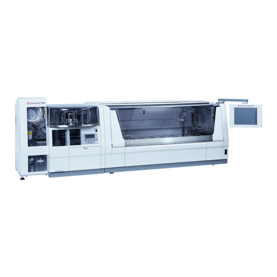
- Page 1 Unpacking and Installation Manual ® Tissue-Tek Prisma Plus Automated Slide Stainer Prisma-P-AD, Prisma-P-AS Prisma-P-ED, Prisma-P-ES DRS-Prisma-P-JD, DRS-Prisma-P-JS DRS-Prisma-P-JCS Document Code: AK6-QE-006-03 Sakura Seiki Co., Ltd. Date: September 27, 2017 Tokyo, Japan...
-
Page 2: Table Of Contents
Table of Contents 1. Intent of the Document ..........................1 2. Important Information ............................. 1 2-1. Overview ............................1 2-2. Precautionary Indication ........................1 2-3. Safety Precautions .......................... 2 3. Workflow ................................ 3 4. Tools Required ............................... 3 5. Installation Conditions and Environmental Requirements ................4 6. -
Page 3: Intent Of The Document
1. Intent of the Document ® This manual explains the unpacking and installation procedure for Tissue-Tek Prisma Plus Automated Slide Stainer. 2. Important Information 2-1. Overview 1) This unpacking and installation work must be done by personnel who have a complete understanding of this manual before the work and skills to perform the procedure as described in the manual. -
Page 4: Safety Precautions
2-3. Safety Precautions Following are the items special attention must be paid to during installation of the system. No Open Flame - Flammable reagents are used in pathology laboratories. It is prohibited to use tools that may product open flame or sparks (such as an electric screwdriver). Electric Shock - Check to be sure that a grounding electrode of a power cord is connected to a grounding of power source. -
Page 5: Workflow
3. Workflow Below is the workflow of installation and system setup. 5. Installation Conditions and Operating Environment 6. Unpacking Workplace 7. Transport to Installation Place 8. Unpacking Procedure 9. Installation 10. Power-on 11. System Setup 12. Delivery to User 4. Tools Required Following is a list of tools necessary for the work. -
Page 6: Installation Conditions And Environmental Requirements
5. Installation Conditions and Environmental Requirements Confirm that the installation place meets the following conditions of 1) to 4). 1) Confirm in advance that the selected installation place is level and solid, providing sufficient clearance around the system shown in Figure 5-1 (installation space). Confirm that the installation place is free of obstacle that may block the ventilation grill on the back of the system. - Page 7 4) Confirm that environmental conditions of the installation place meet the requirements. • Temperature range : +10°C - +40°C • Relative humidity range : 30% - 85% (non-condensing) * The level of noise emitted from the instrument in operation is 65 dB or less (initial sound level). (A-weighted sound pressure level) Measurement method: JIS Z8737-2:2000 (measurement at the point 1.55m high from the floor and 1.0m away from the front of the instrument)
- Page 8 The instrument has a universal voltage system and connectable to the following power source. *1: A clearance required for ・Single phase, AC100V±10% 50/60Hz 15A or more maintenance of the Prisma Plus Outlet with grounding electrode installed alone. ・Single phase, AC115V±10% 50/60Hz 15A or more •...
-
Page 9: Unpacking Workspace
6. Unpacking Workspace Dimensions and weight of the packed instrument are indicated below. Check in advance if there is enough space for safety transportation, unpacking and installation of the instrument. Dimensions and weight of packed instrument Dimensions and weight of unpacked instrument Display Width: approx. -
Page 10: Transportation
7. Transportation 7-1. Transportation to Unpacking Workspace ・Transport the instrument by a forklift or hand pallet truck. When you use a forklift or hand pallet truck, transport the packaged instrument. Insert the forks into fork insert parts of the pallet shown below. Check the size of a forklift or hand pallet truck in advance with reference to the dimensions of the pallet. -
Page 11: Unpacking Procedure
8. Unpacking Procedure This section provides the explanation about how to unpack the carton box of the instrument and remove packing materials. Follow the instructions for safe and proper handling. NOTE ・Inspect the carton box before unpacking and make sure that there are no visible signs of damage that might have been caused by an external force during transportation. - Page 12 (3) Remove foam sheets inserted on both sides of the front cover. Open the front cover and remove foam packing from between the front cover and front door. Foam sheets Foam packing (4) Remove all adhesive tape that holds the top cover in place. Remove foam packing from between the top cover and the accessory box.
-
Page 13: Removing Tape And Foam Packing From The Inside Of The Instrument
8-2. Removing Tape and Foam Packing from the Inside of the Instrument (1) Remove foam packing from between the robotic arm and the slide rail. Foam packing (2) Remove the tape that fastens the basket holder. Remove foam packing from under the holder. (3) Remove foam packing from the reservoir trays. -
Page 14: Selecting The Voltage Setting
8-3. Selecting the Voltage Setting CAUTION • The instrument has a universal voltage system. It is required to select the voltage setting appropriate for a regional supply voltage. • The default setting is 230V. When the instrument is used in a region using a different voltage, change the voltage setting according to the procedure below. -
Page 15: Checking Accessories
* Check if all accessories (listed below) are included with the instrument and also if the instrument and accessories are free from any damage. If they are damaged or missing, contact the nearest Sakura distributor. Description Q’ty... - Page 16 Description Q’ty Remarks Operating manual (English) For 6170, 6171, 6172, 6173 Operating manual (Chinese) For 6177 Medical package insert For 6174, 6175 Installation manual (Japanese and English) Except for 6177 Installation manual (Chinese) For 6177 Warranty and register card For 6174, 6175 10-slide basket For 6171, 6173, 6175, 6177 10-slide basket adapter...
-
Page 17: Installation
9. Installation 9-1. Positioning the Instrument (1) Make sure that the place where the instrument is placed on is sturdy, level and capable of supporting at least 150kg of weight. (2) Lift up the instrument by several people and place it on the installation area. If the installed instrument is unsteady or inclines heavily, adjust the level adjustment feet to make the instrument level. - Page 18 * For Prisma-P-ED and –ES models, be sure to attach the strainer provided with the instrument before connecting the water supply hose as instructed above. Position the strainer as appropriate for a clearance available around the instrument with reference to the illustrations below. For details on how to attach the strainer, see the instruction “<Installation Procedure for Water Supply Strainer for Prisma–P–ED and –ES Models>”...
-
Page 19: Connecting The Drain Hose
9-3. Connecting the Drain Hose ◇ Drain System • Drain capability More than 15 liters per minutes • Pressure No backflow pressure • Location Lower than the drain port of the instrument • Requirements a. The drain system is free from backflow pressure, such as a sink and drainage b. -
Page 20: Installing The Activated Carton Filter
◇ Ventilation system • Ventilation device • Local exhaust device • Exhaust port ◇ Optional items for ventilation • 38mm dia. exhaust duct connection adapter • 75mm dia. exhaust duct connection adapter ◇ How to connect the instrument to a ventilation system (1) Attach the 38mm or 75mm dia. -
Page 21: Power-On
10. Power-On With referring to the section “8-3. Selecting the Voltage Setting”, make sure that the voltage selector switches are properly set. Connect the power cord to the power inlet connector located at the lower right side of the instrument. * Two different power cords come with the instrument. -
Page 22: System Setup Prior To Initial Use
11. System Setup Prior to Initial Use 11-1. Logon and Language Selection Once the instrument is switched on, the message window titled “Please check…” appears. The default language setting is English. Touch the OK button to close the window. Fig. 11-1-1 “Please check…” window Touch the Log On button at the bottom left of the Stain Process Monitor screen (logoff status). - Page 23 Use the numeric keypad to enter the default password “3141” in the Password Input field in the Enter Password window. Touch the Enter button to close the window and logon the system. The Stain Process Monitor screen (logon status) appears. (Fig. 11-1-4) Fig.
- Page 24 From the Utility Menu screen, touch the Language Selection button to display the Language Selection screen (Fig. 11-1-6). Fig. 11-1-5 Utility Menu screen 6) From the Language Selection screen, select the language to be used for system display and then touch the Save button. The screens are displayed in the selected language. (However, the setup procedure in this section uses the English screens.) Fig.
-
Page 25: Adjusting The Date And Time
11-2. Adjusting the Date and Time From the Utility Menu screen (Fig. 11-1-5), touch the System Setup button to display the System Setup screen. Fig. 11-2-1 System Setup screen ・Date Format Select the desired date display format from the options, Year/Month/Day, Month/Day/Year and Day/Month/Year. -
Page 26: Testing The Barcode Reading
11-3. Testing the Barcode Reading ● If the optional barcode reader is not used, the following procedure is not required. From the Utility Menu screen (Fig. 11-1-5), touch the Service Operations button to display the Service Operations screen. Fig. 11-3-1 Service Operations screen Touch the Test Barcode button at the bottom right corner of the Service Operations screen (Fig. - Page 27 Within 10 seconds of the Test Barcode window (Fig. 11-3-2) being displayed, read either one of the following test barcodes according to the predefined setting. SFJ type SFA type Fig. 11-3-3 Test Barcodes When reading the test barcode, check if the barcode reader produces a beeping sound. ...
-
Page 28: Adjusting The Water Flow Rate
11-4. Adjusting the Water Flow Rate Strict Observance ・When adjusting the water flow rate as instructed below, make sure that water does not leak from the connections of water supply hose and drain hose. ◇ Set the wash reservoirs to be used in place prior to adjusting the water flow rate. As a factory default setting, two wash station nozzles are installed in two water supply ports at the right of the water supply manifold and two nozzle caps are installed in the two left water supply ports so that two wash stations can be provided at the right of the 4-position reservoir... - Page 29 Fig.11-4-2 Save water supply run-up time window Fig. 11-4-1 Water Flow screen AK6-QE-006-03 - 26 - 05/2017...
-
Page 30: Installing The Water Station Nozzle
11-5. Installing the Water Station Nozzle Remove the 4-position reservoir tray for wash reservoirs from the instrument. Remove the nozzle cap or water station nozzle already installed. To remove the nozzle cap, turn it counterclockwise. To remove the nozzle, turn the nozzle cap with hole counterclockwise to remove, and then pull the nozzle straight up. -
Page 31: Logoff
11-6. Logoff Touch the Log Off button at the bottom left of the Stain Process Monitor screen (logon status) (Fig. 11-1-4). The confirmation window appears. Touch the Yes button. Fig. 11-6-1 Logoff confirmation window The confirmation window is closed and the system is in the logged-off status. Fig. -
Page 32: Delivery Of The Instrument To A Customer
Miscellaneous 13. Miscellaneous 13-1. How to determine and settle a problem occurred Refer to the section “Troubleshooting” in the operating manual or the information about errors in the service manual or contact the Sakura distributor. AK6-QE-006-03 - 29 - 05/2017... - Page 33 Appendix 1 <Installation Procedure for Water Supply Strainer for Prisma–P–ED and –ES Models> According to a clearance available on the right of the instrument, attach the water supply strainer provided with the instrument to the water supply port before connecting the water supply hose. A.
- Page 34 Appendix 1 B. When a clearance for maintenance work is 100 to 200mm or less on the right of the instrument: In this case, a minimum clearance of about 35mm may be needed on the rear of the instrument. (1) Screw one nipple and bushing into strainer. (2) Screw the other nipple and street elbow into water supply port located on the right side of the instrument.
-
Page 35: Barcodes For Setup
Appendix 2 <Barcodes for Setup> ① ② ③ ④ ⑥ ⑤ ⑧ ⑦ ⑨ AK6-QE-006-03 Appendix- 3/3 09/2017...
Need help?
Do you have a question about the Tissue-Tek Prisma Plus Prisma-P-AD and is the answer not in the manual?
Questions and answers