Sakura Tissue-Tek TEC 6 Operating Manual
Cryo module
Hide thumbs
Also See for Tissue-Tek TEC 6:
- Quick reference manual (4 pages) ,
- Operating manua (104 pages)

Related Manuals for Sakura Tissue-Tek TEC 6


Summary of Contents for Sakura Tissue-Tek TEC 6
- Page 1 Tissue-Tek ® ™ Cryo Module Operating Manual Part Number M01-022E-01 Revision Letter Original Released 2018-08-03...
- Page 2 The brand names of products that have been registered or trademarked by and are owned by Sakura Finetek USA, Inc., Sakura Finetek Japan Co., Ltd., and Sakura Finetek Europe B.V. appear here: Sakura Tissue-Tek © 2018 Sakura Finetek Japan Co., Ltd.
-
Page 3: Table Of Contents
Table of contents 1. Introduction Intended Use …………………………………………………………7 Safety Precautions …………………………………………………8 Precautions for Use ……………………………………………… 13 Overview of the Instrument …………………………………… 14 1.4.1 Instrument Configuration ……………………………… 14 1.4.2 Specifications …………………………………………… 15 Accessories ……………………………………………………… 16 1.5.1 Standard Accessories (Cryo Module) ………………… 16 Description of Instrument Parts ………………………………... - Page 4 Cleaning …………………………………………………………… 45 5.2.1 Inspection and Cleaning ………………………………… 45 5.2.2 Cleaning the Cryo Module ……………………………… 45 6. Replacement Parts Replacement Parts ……………………………………………… 47 6.1.1 Cryo Module …………………………………………… 47 7. Glossary of Terms Glossary of Terms ……………………………………………… 49...
- Page 5 Table of contents...
-
Page 6: Introduction
1. Introduction... -
Page 7: Intended Use
1. Introduction 1.1 Intended Use ® ™ The Tissue-Tek 6 Cryo Module (hereinafter referred to “the instrument”) is intended to embed processed human or animal tissue in paraffin by cooling blocks which contain tissues and paraffin on cassettes after dispensing molten paraffin. -
Page 8: Safety Precautions
1.2 Safety Precautions Designate the "Instrument Control Manager." • Operation of the instrument requires expert knowledge of the target application, method of use, and so on. Therefore, to use the instrument correctly and safely, designate an "Instrument Control Manager." • When the instrument is delivered, the Instrument Control Manager should receive explanation on the handling of the instrument directly from the staff trained in the instrument or distributor. - Page 9 1. Introduction The symbols used on the labels attached to the instrument are explained. The labels bearing one of the following symbols provide particularly important information you must know in order to ensure safety of the operator, improve work efficiency and protect the instrument from damage. Be sure to check these labels and understand the specified instructions before commencing your work A label bearing this symbol specifies an action that must be taken.
- Page 10 If the power cord or power plug has scratches or other abnormalities, contact a Sakura instrument distributor or representative. • Check the power cord and electrical outlet for damage and accumulated dust periodically.
- Page 11 Perform periodic inspection of the instrument every 6 months. Perform periodic inspection of the instrument every 6 months to ensure safe use of the instrument and maintain its performance. For details on periodic inspection, contact a Sakura instrument distributor or representative. •...
- Page 12 • Precautions when installing the instrument (Installation) Do not put down the instrument in an unstable place or on a floor or surface with insufficient strength. • How to remove dew condensation water. Remove dew condensation on the cooling plate before dew condensation water flows out of the frame.
-
Page 13: Precautions For Use
1. Introduction 1.3 Precautions for Use CAUTIONS: • Precautions when installing the instrument (installation) Do not put down the instrument in an unstable place or on a bench or surface with insufficient strength. Doing so may cause injury. Install the instrument in a location meeting the installation conditions. Dew condensation, etc. -
Page 14: Overview Of The Instrument
1.4 Overview of the Instrument 1.4.1 Instrument Configuration The instrument comprises of the cooling plate that cools/solidifies the embedded paraffin blocks. CAUTION: CAUTION The Cryo Module is controlled by the Embedding Module which is connected to the Cryo Module by the control cable. The Cryo Module cannot be used alone. -
Page 15: Specifications
1. Introduction 1.4.2 Specifications General name Paraffin-embedded block preparation system ® ™ Brand name Tissue-Tek 6 Cryo Module Model TEC 6-CM-J0 TEC 6-CM-A1 TEC 6-CM-E2 TEC 6-CM-JC2 Product code 5105 5109 5113 5117 Manufacturing license number 20B2X00014000036 330 (W) × 617 (D) × 377 (H) mm Dimensions (Cold plate size:300 (W) ×... -
Page 16: Accessories
1.5 Accessories 1.5.1 Standard Accessories (Cryo Module) [TEC 6-EM-J0] [TEC 6-CM-E2(JC2)] [TEC 6-CM-A1] Quantity Item name Product code TEC 6-CM-J0 TEC 6-CM-A1 TEC 6-CM-E2 TEC 6-CM-JC2 Power cord A4010527 A4010539 A4010535 Control cable A4120001 Operating Manual... -
Page 17: Description Of Instrument Parts
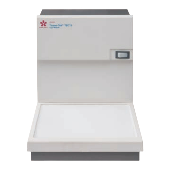
1. Introduction 1.6 Description of Instrument Parts 1.6.1 Instrument (Front Side) [1] Power switch A switch for the main power supply. The lamp is turned on while power is supplied. [2] Cooling plate A cooling plate that cools/solidifies the embedded paraffin block. 1.6.2 Instrument (Rear Side) [1] Power inlet Connect the power cord here. -
Page 18: 2. Installation
2. Installation... -
Page 19: Installation
2. Installation 2.1 Installation 2.1.1 General Information on Installing the Instrument This section provides information on determining a location for and installing the instrument. Installation should be performed by trained staff for the instrument. This instrument must be installed correctly to ensure proper operation and service. Read this Operating Manual carefully before operating the instrument. -
Page 20: Unpacking Method Of The Cryo Module
2.1.3 Unpacking Method of the Cryo Module How to remove the instrument from the packing box that has been carried in, and remove the protective materials, is explained in this document. To perform each work safely and correctly, be sure to follow the procedure specified herein. - Page 21 2. Installation 3. Take out the Operating Manual, the power cord in the cushioned packing materials, and control cable from the rear of the instrument. 取扱説明書 Operating Manual 電源コード Power cord 制御ケーブル Control cable 4. Remove the sleeve. 5. Remove the plastic sheets covering the instrument. 6.
-
Page 22: Installation Method
Operating Manual Inside the box 2.1.4 Installation Method If you have any questions on how to install the instrument, contact the Sakura instrument distributor or representative. Before moving the instrument, if it has been previously installed, confirm that no molten paraffin is left inside the Embedding Module or any paraffin left in the module is cool and solid. - Page 23 2. Installation placed according to your desired work flow. (The cables will be connected to the rear of the instrument, so do not place the instrument close to the walls yet.) 作業の流れ 作業の流れ Work Flow Work Flow Connecting the Cables 1.
- Page 24 4. Insert the power plug of each module into an electrical outlet with grounding terminals. Power supply system meeting the following conditions is needed to connect the power plugs: Voltage: 100VAC 115VAC 230VAC Capacity: 15 A or more 15 A or more 10 A or more 15 A or more 15 A or more...
-
Page 25: Setting Up The Instrument
2. Installation 2.2 Setting Up the Instrument Set the control temperature for each part of the instrument, auto operation and current time. Perform these settings on the control panel display of the Embedding Module. 2.2.1 Temperature Setting for Each Part of the Instrument The heating and cooling parts of the instrument are temperature-controlled at their respective set values. - Page 26 Status of the Temperature Display Area The temperature control status of the paraffin heating part is indicated by the display color of the temperature display area. •Temperature control is inactive (paused) > Gray •Temperature control is active (preparing, operating) > Orange NOTE: Each temperature indication is blinking during preparation.
- Page 27 2. Installation Setting the Temperature 1. Turn on the Embedding Module power switch. NOTE: The power switch of the Cryo Module may be off. Also note that Cryo Module temperature can be set even when the control cable is not connected. 2.
-
Page 28: Setting The Schedule Of The Auto Operation
2.2.2 Setting the Schedule of the Auto Operation (with the Auto Cryo Mode) This instrument is operated in the auto mode and manual mode. In the auto mode, the instrument is automatically activated so that paraffin has melted sufficiently when the start time arrives. When the end time arrives, the instrument automatically pauses. - Page 29 2. Installation 5. To set times separately for each day of the week, touch the time corresponding to a desired day of the week. The Auto Operation Settings screen is displayed. The “ “ field at the top indicates * “Hours” changes by 1 at a time. “Minutes” changes the start time.
-
Page 30: Operational Overview
2.3 Operational Overview 2.3.1 Operation Method Select one of two operation methods of the instrument: manual or auto. Instrument State The Cryo Module has one of the states shown in the table below. State Description Remarks Paused Temperature control is stopped. Active Preparing Temperature control is active... - Page 31 2. Installation Details of the Auto Operation Mode • Cryo Module Auto operation of the Cryo Module is performed with the Auto Cryo mode on or off, as selected. * Auto Cryo mode on: The Cyro Module activates/pauses automatically in conjunction with the auto operation of the Embedding Module.
-
Page 32: 3. Explanation Of Operations
3. Explanation of Operations... -
Page 33: Explanation Of Operations
3. Explanation of Operations 3.1 Explanation of Operations 3.1.1 Basic Operations For the basic operations of the Cryo Module, refer to the Operating Manual ® ™ for the Tissue-Tek 6 Embedding Module. -
Page 34: 4. Error Log
4. Error Log... -
Page 35: Error Log
4. Error Log 4.1 Error Log 4.1.1 Viewing the Error Log For details on how to view the error log, refer to the Operating Manual for the ® ™ Tissue-Tek 6 Embedding Module. -
Page 36: 5. Troubleshooting
5. Troubleshooting... -
Page 37: Troubleshooting
Turn on the power switch again. If the problem is repeated after the power switch is turned back on, the instrument may be faulty. Contact the Sakura instrument distributor or representative. The “Cryo” button is The control cable is not connected. -
Page 38: Message Window
5.1.2 Message Window When an error occurs, notification with buzzer sounds and message window are displayed on the current screen at the same time. There are two types of messages: caution messages and warning messages. NOTE: If a new error occurs while the message window is still displayed, the new message is put on hold. - Page 39 (“Paused” state). power, contact the Sakura in s tr ume nt dis tr ibu to r o r representative. E003...
- Page 40 Wait for a while, and if the chamber. temperature does not stop Something is placed on blinking, contact the Sakura the hot plate. in s tr ume nt dis tr ibu tor or representative. Ambient temperature is (C h e c k if a ny e quip m e nt too low.
- Page 41 Cryo Module. I f t h e p r o b l e m p e r s i s t s , contact the Sakura instrument distributor or representative. E040 Low battery...
- Page 42 Error Displayed Instrument operation Overview Description Solution code message when the error occurs E103 Abnormally Abnormally high The temperature of each Operation aborts. u r n of f t h e p owe r to t h e high temperature l o c a t i o n exc e e d s t h e instrument.
- Page 43 5. Troubleshooting Descriptions of Additional Codes Additional code Description (Applicable location) Cooling plate (Cryo Module) Paraffin chamber (Embedding Module) Left side warming chamber (Embedding Module) Right side warming chamber (Embedding Module) Left side hot plate (Embedding Module) Right side hot plate (Embedding Module) Paraffin line (Embedding Module) Dispensing solenoid valve (Embedding Module) Dispenser (Embedding Module)
-
Page 44: What To Do Following A Power Outage
5.1.3 What to Do Following a Power Outage If a power outage occurs when the Cryo Module is not in the “Paused” mode, the temperature control stops and therefore the cooling plate temperature will start to rise. Turning off the power switch or removing the power plug is essentially the same as a power outage. -
Page 45: Cleaning
5. Troubleshooting 5.2 Cleaning Inspect and clean the instrument and replace consumables as described in this manual, to prevent instrument malfunction and failure. 5.2.1 Inspection and Cleaning When inspecting or cleaning the instrument, be careful not to get burned by the molten paraffin or the hot water used for cleaning. -
Page 46: 6. Replacement Parts
6. Replacement Parts... -
Page 47: Replacement Parts
6. Replacement Parts 6.1 Replacement Parts When replacing consumables or options, use the parts specified in this manual. Use of other parts may result in malfunction or failure. 6.1.1 Cryo Module Quantity Description Product code TEC 6-CM-J0 TEC 6-CM-A1 TEC 6-CM-E2 TEC 6-CM-JC2 Power cord A4010527... -
Page 48: 7. Glossary Of Terms
7. Glossary of Terms... -
Page 49: Glossary Of Terms
7. Glossary of Terms 7.1 Glossary of Terms Auto operation An operation mode where the instrument starts up automatically to be ready for the embedding work at the preset start time and comes to a pause at the preset end time. Base mold tray A tray that accommodates base molds of various sizes used for embedding process. - Page 50 Foot pedal (optional) A foot pedal for dispensing paraffin used for embedding. Pressing the switch starts dispensing, and releasing it stops dispensing. The finger plate functions even when the foot pedal is connected. Forceps holder A forceps holder for keeping the various types of forceps used for embedding process, warm (temperature cannot be set).
- Page 51 7. Glossary of Terms Start time A time at which the instrument is ready to use in the auto operation mode. The instrument calculates an automatic “start-up” time from the preset start time. Tamper A tamper is a tool used to fix the position of tissue in the base mold during embedding.
- Page 53 M01-022E-01...
- Page 54 Please visit our websites: www.sakura-finetek.com www.sakuraus.com www.sakura.eu...
Need help?
Do you have a question about the Tissue-Tek TEC 6 and is the answer not in the manual?
Questions and answers