Table of Contents
Advertisement
Advertisement
Table of Contents
Troubleshooting

Related Manuals for Sakura Tissue-Tek Glas g2


Summary of Contents for Sakura Tissue-Tek Glas g2
- Page 2 All Rights Reserved Printed in U.S.A. Manufactured for: Sakura Finetek USA, Inc., Torrance, CA 90501 U.S.A. Sakura Finetek Japan Co., Ltd., Tokyo, 135-0007, Japan Sakura Finetek Europe B.V., 2804 AV Alphen aan den Rijn, NL Made in Japan 0002783-01 Rev.B...
-
Page 3: Table Of Contents
TABLE OF CONTENTS Section Page INTRODUCTION Safety Precautions ........................ 1.1 General Description ....................... 1.2 Physical Characteristics ......................1.3 Specifications ........................1.7 INSTALLATION General Information ......................2.1 Environmental Factors......................2.1 Unpacking ..........................2.1 Installation of Accessories and Consumable Supplies ............2.3 CUSTOMIZATION OF SETTINGS General Information ...................... - Page 4 TABLE OF CONTENTS Section Page TROUBLESHOOTING General Information ......................6.1 Troubleshooting Table......................6.2 Actions to take upon Generation of Errors, Cautions, and Warnings ........6.3 APPENDIX A GLOSSARY Glossary ..........................A.1 APPENDIX B WARNINGS AND CAUTIONS Warnings ..........................B.1 Cautions ..........................B.2 APPENDIX C NOTES ON USE Notes on Use .........................
-
Page 5: Introduction
Section 1 INTRODUCTION Safety Precautions The symbols used on the labels attached to the system are explained below. Labels bearing one of the ™ Operation of the Tissue-Tek ® Glas g2 Automated following symbols provide particularly important Glass Coverslipper requires expert knowledge of the information to know in order to ensure safety of the target application as well as method of use. -
Page 6: General Description
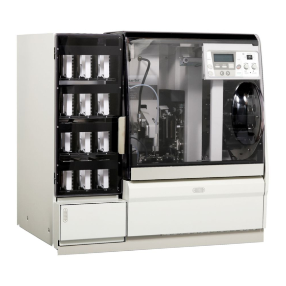
INTRODUCTION General Description • Up to 240 slides (corresponding to 12 baskets) can be coverslipped in a continuous manner. ® The automatic coverslipper Tissue-Tek Glas ™ • The dispense volume of mounting medium and (Figure 1-A) is a system that dispenses mounting medium coverslipping speed can be adjusted in real time. -
Page 7: Physical Characteristics
Section 1 Physical Characteristics Figure 1-C Figure 1-B Back Side (Figure 1-C) Front Side (Figure 1-B) Exhaust outlet Cover —Air from the interior of the system is — Open this cover to fill cover glass or remove an empty basket. exhausted through this outlet. - Page 8 INTRODUCTION [14] [15] [16] [12] [13] Figure 1-D [17] [11] [10] Instrument Interior (Figure 1-D) Mounting medium bottle area .11. —A 500 mL bottle containing mounting medium must be placed in this area. ® For best results, use the Tissue-Tek Glas Mounting ™...
- Page 9 Section 1 [25] [26] [27] [27] [24] [23] [31] [30] [29] [28] Figure 1-E Instrument Interior (Figure 1-E) Dispensing nozzle down lever — This lever is used .26. Station 1 (slide retrieval) . — The slide retrieval arm to lower the dispensing nozzle and dip it in the anti-drying takes out slides from the baskets and places them in this bottle.
- Page 10 INTRODUCTION [10] [14] [12] [13] [15] Figure 1-F Control Panel (Figure 1-F) POWER switch .1. — This switch is used to turn the STOP key — Use this key to pause the coverslipping power on/off. operation or cancel the initial priming of mounting medium. START key POWER lamp —...
-
Page 11: Specifications
Section 1 Specifications Instrument Weight Approximately 110 kg (242.5 lbs) Models Model Name/Description Operating Conditions ® ™ Tissue-Tek Glas g2 Automated Glass Coverslipper 6500 (115 VAC) (USA) Operational Temperature: 10°C to 40°C (50°F to 104°F) ® ™ Tissue-Tek Glas g2 Automated Glass Coverslipper Relative Humidity: 30-85% (non-condensing) 6501 (100 VAC) (Asia) - Page 12 INTRODUCTION Revised 3/30/2010...
-
Page 13: General Information
CAUTION: The instrument is very heavy and large; the instrument. Follow all instructions carefully. therefore, it is strongly recommended that it always The Tissue-Tek Glas g2 Coverslipper is a precision be lifted and transported by at least two people, one instrument and must be handled accordingly. Rough positioned on each side. - Page 14 INSTALLATION & SETUP Unpacking the Accessories (Figure 2-A) Shipped separately: • ® Tissue-Tek Glas Mounting Medium, product ™ code 6419 When opening the accessory box, confirm that all accessories have been included with the instrument: 20-Slide basket adapter (10), product code 6138 20-Slide baskets (10), product code 4768 Receiving racks (12), product code 6504 Power cord (1), product code A40-105-11...
-
Page 15: Installation Of Accessories And Consumable Supplies
Section 2 Installing the Receiving Rack (Figure 2-E) Installation of Accessories and Consumable Supplies 1. Open the unloading door. 2. Grab the receiving rack (Figure 2-F) handle in such a Installation of Accessories way that the slide unloading area faces to the right side, and then place the receiving rack in the This section explains how to install the various recessed area of the unloading area (indicated by the... - Page 16 INSTALLATION & SETUP Installing the Loading Station Align the direction of the basket receiver with the direction of the loading station. Insert the pin inside the loading station into the hole in the basket receiver, then insert the loading station all the way to the end (Figure 2-H &...
- Page 17 Section 2 Connecting the Power Cable 1. Turn the power switch to OFF. 2. Connect the power cable to the power inlet on the system (Figure 2-L). 3. Connect the power plug to a power outlet with a grounding terminal (3P). Figure 2-N Power inlet Mounting medium...
- Page 18 INSTALLATION & SETUP 5. Place the anti-drying bottle and waste container in the dispensing tray (Figure 2-P). First, push back the dispensing nozzle in and then place the bottle (Figures 2-Q, 2-R, & 2-S). Dispensing tray Figure 2-S Waste Container Anti-drying Waste bottle...
- Page 19 (Figure 2-X), it is possible to link the ® system with automatic stainer (Tissue-Tek Prisma ™ For details on installing the link system, consult the Sakura dealer. Figure 2-U Aperture Figure 2-X Figure 2-V Cover glass tray Revised 3/30/2010...
- Page 20 INSTALLATION & SETUP Exhaust Hose Installing the Activated Carbon Filters By opening an adapter to connect an exhaust hose is 1. Press on the front of the fume control door to release provided at the back of the system. A hose with a the lock, and then pull out the fume control door diameter of 38 or 75 mm can be connected.
- Page 21 Section 2 Installing the Mounting Medium Bottle Adjusting the Gap along the Mounting Medium Bottle The mounting medium suction tube is equipped with a level detection sensor. Set the tube and sensor correctly. 1. Loosen the two screws at the cap installation mechanism.
- Page 22 INSTALLATION & SETUP Placing the Cover Glasses NOTE: Place commercial holders provided by cover glass manufacturers directly in the system. Dedicated cover glass holders are also provided as options (sold separately). When using dedicated cover glass holders, place cover glasses in the holders (Figure 2-DD). 1.
-
Page 23: Customization Of Settings
Section 3 CUSTOMIZATION OF SETTINGS General Information 4. PROGRAM EDIT- Sets the names and details of coverslipping programs that specify coverslipping conditions. Up to nine coverslipping programs can be This section explains the operations of the main menu stored in memory, each specifying a different cover screen and how to change each setting. - Page 24 CUSTOMIZATION OF SETTINGS Viewing/Changing the Count <COUNT RESET> Are you sure? How to view/change the number of slides that have been coverslipped is explained (Figure 3-B). NOTE: This menu item is available only when the system [ENTER] to reset is on standby or paused, or when the system check screen is displayed.
- Page 25 5. Open the cover and take out the entire dispensing priming. For details, contact the Sakura Customer tray from the system. Remove the entire dispensing Service Center the Sakura local distributor.
- Page 26 CUSTOMIZATION OF SETTINGS Viewing the Error Log Creating a Program Up to 99 errors can be displayed, with the newest A program consists of three items, namely CG (cover glass) size, volume of mounting medium, and number representing the latest error. coverslipping speed.
- Page 27 Section 3 Selecting the Key Sound 5. When the MENU key is pressed once again, the program edit screen appears (Figure 3-J). This function allows the key sound to be turned on/off. NOTE: This menu item is available only when the system <P1:HE-1 >...
- Page 28 CUSTOMIZATION OF SETTINGS 4. Press the < and > keys to select a desired option from <ALARM> 1, 2, and 3. 1 / 2 / 3 / 4 • Pattern 1 A short “beep” sound is output six times repeatedly. [<][>] to select •...
- Page 29 Section 3 Cleaning the Interior of the Mounting <CLEANING> Medium Tubing In process The purpose of this procedure is to clean the interior of the mounting medium tubing using a solvent, preferably [STOP] to stop xylene. Do not use this cleaning function to prime the mounting medium as the flow rate is too high and will Figure 3-R: Cleaning in Progress Screen generate air bubbles in the line...
- Page 30 CUSTOMIZATION OF SETTINGS Explanation of Sub Menu Items 1. SLOWDOWN POSITION- This function changes the pressure applied when the cover glass is placed on the slide. Use this menu item mainly when air bubbles This section explains the operations available from are present or mounting medium is seeping out the sub menu screen and how to change each setting around the slide.
- Page 31 Section 3 Setting the Slowdown Position 1. Press the MENU key twice. 2. Press the < and > keys to highlight 1, “Slowdown To change the pressure applied to the cover glass position,” and then press the ENTER key. The during coverslipping, use this function (Figure 3-U).
- Page 32 CUSTOMIZATION OF SETTINGS Setting the Cover Glass Angle Use this function to select a desired angle at which to Coverslipping arm pick up the cover glasses. NOTE: This menu item is available only when the system is on standby or paused or when the system check screen is displayed.
- Page 33 Section 3 Setting the Slide Pickup Speed <Pick-up speed> Use this function to select a desired speed at which to 1 / 2 / 3 / 4 / 5 pick up the slide. [<][>] to select NOTE: This menu item is available only when the system [ENTER] to save is on standby or paused or when the system check screen is displayed.
- Page 34 CUSTOMIZATION OF SETTINGS Setting the Dispense Point 5. Press the ENTER key to save the selected setting (Figure 3-CC). To return to the menu screen without saving the change, press the EXIT key. To select the initial position at which to start dispensing mounting medium onto the glass slide, use this function.
- Page 35 Section 3 Setting the First Dispense Volume <First Dispense> During coverslipping, mounting medium is dispensed Offset:0 twice. For the first dispense action, the nozzle remains [<][>] to select stationary and mounting medium is dispensed at the [ENTER] to save current position. For the second dispense action, mounting medium is dispensed as the nozzle moves Figure 3-EE: First Dispense Volume Setting Screen (Figure 3-DD).
- Page 36 CUSTOMIZATION OF SETTINGS 3.14 Revised 3/30/2010...
-
Page 37: Operating Instructions
Section 4 OPERATING INSTRUCTIONS Operating Instructions Pre-Operational Checks This section explains the sequence of operating This section explains the required steps before procedures. The basic flow of operation is shown in the operation. chart below. Flow of Coverslipping Operation Chart Turning On the Power 1. - Page 38 OPERATING INSTRUCTIONS Checking the Solvent Volume If the solvent volume in the loading station, anti-drying bottle, or dispensing pump reservoir is at or below the specified level, add solvent. Loading station (Figure 4-A) The loading station can accommodate approximately 1.5 L of solvent (use of xylene is recommended).
- Page 39 Section 4 Cleaning Spilled Mounting Medium If mounting medium remains attached to the waste containers and receiving racks, coverslipping may be affected. Before coverslipping is started, clean the waste containers and receiving racks or replace them with clean Figure 4-D ones.
- Page 40 OPERATING INSTRUCTIONS Removal of Baskets in the Carousel Checking the Volume of Mounting Medium After all glass slides have moved to the coverslipping Check the volume of mounting medium in the station, the empty baskets will be stored in the carousel. If mounting medium bottle.
- Page 41 Section 4 Routine Operations Checking the Dispense of Mounting Medium Start of Operation Press the PRIME key to check if mounting medium is dispensed properly. Press and hold the PRIME key for 3 This section explains the start of operation. seconds, and mounting medium will be dispensed 10 Before instrument operation begins, the following times consecutively.
- Page 42 OPERATING INSTRUCTIONS Placing Slides in a Basket CAUTION: Set slides in parallel with the basket partitions. If slides are tilted, they may be damaged 1. Prepare slides to be coverslipped. Check the stainer (Figure 4-I). station layout and prepare an appropriate basket (20- slide basket or 10-slide basket) as well as a basket adapter appropriate for the basket.
- Page 43 Section 4 Placing a Basket in the Loading Station 1. Confirm that the LOAD lamp on the right side of the control panel is on. While the lamp is not on, baskets cannot be placed. 2. Open the loading station access door, grab the handle, and then slide out the loading station receiver.
- Page 44 OPERATING INSTRUCTIONS Starting the Process After the program has been selected, cover glass, coverslipping speed and volume of mounting medium have been specified, and a basket has been placed, press the START key or open and close the unloading station door, depending on the start method selected (see page 3.7).
-
Page 45: Operations Permitted During Operation
Section 4 Operations Permitted during Operation In the example shown above, rack 1 has been there for more than the drying time and can be removed. Drying of rack 2 is not yet completed. The following operations can be performed during coverslipping. - Page 46 OPERATING INSTRUCTIONS Pausing the Process Resuming the Process To pause the process, press the STOP key on the To resume the paused process, press the START control panel. Note that the process cannot be paused key. The process will resume. At this time, a caution during initial priming or while the dispensing tubing is screen will appear if the loading station access door is being cleaned.
-
Page 47: End Of Coverslipping
Section 4 End of Coverslipping When all slides present in the loading station have been coverslipped and the receiving racks are ready for removal, a sound is output to notify the end of coverslipping. The system will stop, and will display the standby screen on the control panel. -
Page 48: End Of Operation
OPERATING INSTRUCTIONS End of Operation 5. Push the lever down to the left (Figure 4-U). The dispensing nozzle comes down and its tip dips into the liquid in the anti-drying bottle (Figure 4-V). This section explains the operating procedure to be carried out after the system operation has ended. -
Page 49: Actions To Be Taken Upon Power Outage During Operation
Section 4 Upon Restoration of Power Actions to Be Taken upon Power Outage during Operation After the power has been restored, perform the reset operation by following the procedure below: This section explains the procedure to be followed 1. Press the “|” side of the power switch to turn on the when a power outage occurs during operation, as well as power. - Page 50 26 mm (width) x 76 mm (length) x 0.9 to 1.2 mm (thickness) Adjust the system according to the slide glass used. For details, consult the Customer Service Center or the Sakura dealer. Mounting medium has solidified on or in the tip of the Remove the solidified mounting medium.
- Page 51 The pressure applying the cover glass during coverslipping Increase the cover glass application pressure. For details, is too weak. consult the Customer Service Center or the Sakura dealer. The starting position of the application of mounting medium Change the start position for application of mounting not appropriate.
- Page 52 Decrease the cover glass application pressure. For details, slide becomes coverslipping is too strong. consult the Customer Service Center or the Sakura dealer. dirty with The starting dispensing position of mounting medium is not Change the start position of dispense of mounting medium.
-
Page 53: How To Operate The G2 When Linked To The Prisma
Section 4 How to Operate the g2 when Linked to the 3. Select In Use under Coverslipper Link, and select Prisma Tissue-Tek ® Prisma ® Slide Stainer Tissue-Tek Glas under Coverslipper (Figure 4-Y). This section explains how to set up the Prisma when the g2 is linked to the Prisma. - Page 54 OPERATING INSTRUCTIONS How to Start from the Prisma 6. Confirm that Yes is selected for Link With Coverslipper in the System Setup tab (Figure 4-AA). 1. Press the START key on the monitor screen. 2. When the display switches to the process start screen (Figure 4-CC), select a staining program and a coverslipping program.
- Page 55 Section 4 3. Press the ENTER key on the numeric keypad to 5. After confirming the staining program and the loading confirm the coverslipping program, and confirm that station where the baskets have been placed, press the program number has been changed (Figure 4- the START key to start the process (Figures 4-GG &...
- Page 56 OPERATING INSTRUCTIONS 4.20 Revised 3/30/2010...
-
Page 57: Care Of Instrument
Section 5 CARE OF THE INSTRUMENT General Maintenance 6. Remove each waste container and replace it with a clean container. Keep the exterior of the instrument free of dust at all Check the spatula part of the removed waste times. If needed, the exterior may be cleaned using a container for deformation or damage. - Page 58 Contact the receiving rack in the solvent for 24 hours to dissolve the attached mounting medium. the Sakura Customer Support Department or the local Sakura distributor. Remove the receiving rack and let it dry completely.
-
Page 59: Troubleshooting
If additional assistance is required concerning an instrument problem, or if the problem cannot be isolated or is beyond the scope of this manual, please contact the Technical Support Department by calling (800) 725-8723, option 2 (U.S. only) or call the local Sakura distributor. Revised 3/30/2010... -
Page 60: Troubleshooting Table
The receiving rack is damaged. Contact the Customer Service Center or the Sakura distributor. The processing capacity drops The cover-glass level detection function was Press the STOP key and add cover glasses, and the... -
Page 61: Actions To Take Upon Generation Of Errors, Cautions, And Warnings
Section 6 Actions to Take upon Generation 3. When the error screen shown below appears (Figure 6-C), retain the cover glass currently being picked up of Errors, Cautions, and by the suction pads and then press the ENTER key. The cover glass will be released the moment the Warnings ENTER key is pressed. - Page 62 TROUBLESHOOTING Revised 3/30/2010...
-
Page 63: Glossary
Appendix A GLOSSARY Glossary of Terms Basket: A staining basket holding slides that have not yet been coverslipped. 40-mm CG: Receiving rack: A cover glass with a length of 40 mm. A rack for holding slides that have been coverslipped. 50-mm CGC: Loading station: A cover glass with a length of 50 mm. - Page 64 APPENDIX A Revised 3/30/2010...
-
Page 65: Warnings
Should any damage or other abnormality on the power cable or plug be found, contact Do not disassemble or modify the system. the Sakura dealer. The system may malfunction or cause an accident. Handle reagents (organic solvents) with Do not open covers and doors unless due care. -
Page 66: Cautions
Provide sufficient airing and ventilation around the that the system will be used safely and continue to system. demonstrate the desired performance. Contact the Sakura Close the lids on containers during dealer for the details of periodic inspection. operation. -
Page 67: Notes On Use
Appendix C NOTES ON USE Notes on Use Read this “Notes on Use” section beforehand to ensure the correct use of the system. This section explains the items that should be heeded to prevent system failures, as well as items that should be noted to perform proper coverslipping operation. - Page 68 APPENDIX C Notes for Proper Coverslipping Operating Put a sufficient amount of clearing agent (mainly xylene) in the loading station to prevent tissues from drying up. Determine the operating conditions after a coverslipping test. The operating conditions of the system vary depending on the tissues on the slide. Conduct a physical coverslipping test using the system before determining the operating conditions.
Need help?
Do you have a question about the Tissue-Tek Glas g2 and is the answer not in the manual?
Questions and answers