
Related Manuals for Sakura Tissue-Tek Prisma Plus


Summary of Contents for Sakura Tissue-Tek Prisma Plus
- Page 1 ® Tissue-Tek Prisma Plus Automated Slide Stainer Operating Manual Part Number M01-019E-04 Revison Letter B Revised 2018-02-01...
- Page 2 Manufactured for: Sakura Finetek U.S.A., Inc. Torrance, CA 90501, USA Sakura Finetek Europe B.V., 2408 AV Alphen aan den Rijn, NL Sakura Finetek Japan Co., Ltd. Tokyo, Japan 103-0023 Manufactured by: Sakura Seiki Co., Ltd. Nagano, Japan...
-
Page 3: Table Of Contents
Table of Contents Safety Precautions ........................... (e) Explanation of Terms..........................(p) Chapter 1 Basics of the System Installation Method ..........................1-1 Installing the Instrument ........................1-1 Flow of Installation ........................... 1-1 Required Tools ..........................1-1 Installation Environment ........................1-1 Checking the Installation Conditions ....................1-2 Cecking the Work Area ........................ - Page 4 Explanation of Icons in the Utility Menu ..................1-34 Edit Menu ............................1-35 Explanation of Icons in the Edit Menu ................... 1-35 System Setup ............................1-36 System Setup ............................ 1-36 Setting Date and Time ........................1-38 Entering Year ..........................1-38 Entering Month ..........................
- Page 5 Applicable Solutions .......................... 2-34 How to Use Sakura Staining Solutions ..................... 2-34 Editing a Solution Configuration ....................2-34 How to Enter Sakura Solution Bar Code Data................2-35 How to Use Sakura Staining Kit ......................2-36 Editing a Solution Configuration ....................2-36 How to Enter Kit Component Solution Bar Code Data ..............
- Page 6 Action to Be Taken upon Power Outage ....................2-46 Power Recovery Operation ....................... 2-46 Action to Be Taken upon Error ......................2-47 Error Handling ........................... 2-47 Errors with a Number ........................2-47 Other Errors ........................... 2-47 Chapter 3 Maintenance and Inspection Daily Inspection and Cleaning ........................
-
Page 7: Safety Precautions
Safety Precautions Designation of "Instrument Control Manager" ● Operation of the instrument requires expert knowledge of the target application, method of use, and so on. So that the instrument can be used correctly and safely, designate a "Instrument Control Manager." ●... - Page 8 The instrument may malfunction or cause accidents. ● Avoid connecting the instrument to a transformer not manufactured by Sakura Finetek. When moving the instrument to a region where different voltage is used, contact the Sakura Finetek Technical Support representative or local representative. ●...
- Page 9 If water, metal, paper or other foreign matter enters the air inlets (to the fan, etc.), fire, electric shock, injury of the user, instrument failure, etc., may occur. If foreign matter entered the instrument, immediately stop the instrument and contact the Sakura Finetek Technical Support representative or local representative.
- Page 10 Using the instrument in a humid place, place exposed to oil smoke or steam, or dusty place, may cause its parts to deteriorate, short-circuit, fire, etc. The installation humidity range is 30 to 85% (non- condensing). If you wish to install the instrument in a special place, consult the Sakura Finetek Technical Support representative or local representative.
- Page 11 Safety Precautions CAUTION ● Do not pinch the drain hose or allow it to slacken. Water will not be drained properly and overflow from the instrument. ● Set the solution station (tray) in the correct location. If not, the tissues may not be soaked in the solution and staining problems may occur. ●...
- Page 12 Safety Precautions CAUTION ● Do not allow any foreign object to be caught between the cover/door and the stainer. It may cause an unexpected problem. ● Use tap water for the water supply. Use of water containing pollutants may result in staining problems. ●...
- Page 13 Safety Precautions CAUTION ● When the pull-up speed is increased, more solution will be brought into the next station and accelerate solution deterioration, resulting in lower staining quality. There are also risks of tissue contamination due to dropping solution. ● Do not stare at the laser beam from the 2D bar code reader.
- Page 14 ● If the instrument must be moved after installation, contact the Sakura Finetek Technical Support representative or local representative. Unexpected accident may occur by relocating the instrument, so contact the Sakura Finetek Technical Support representative or local representative. ● Use designated consumable parts.
- Page 15 To unplug the power cord from the power outlet, do not pull the cord, but hold the plug and then pull it out. Inspect the power cord periodically. If any damage is found in the exterior of the power cord, stop using it and contact the Sakura Finetek Technical Support representative or local representative. ●...
- Page 16 ● If an error (trouble) occurs, staining problems may occur. Immediately resolve the error, protect the tissues, and contact the Sakura Finetek Technical Support representative or local representative. Connect an external alarm to prevent staining problems from happening when the instrument experiences problems.
- Page 17 Safety Precautions CAUTION ● Exercise due caution when handling solutions. Follow the relevant regulations and guidelines in your country or region and take proper measures to protect the operator, such as wearing gloves, mask and/or safety goggles. Some solutions are toxic or harmful to the human body. Some solutions are very flammable, combustible, and/or harmful to human body.
-
Page 18: Explanation Of Terms
Explanation of Terms ● Mix To cause a basket to move up and down inside a solution-filled station before or after the basket is transferred. ● Enhanced Wash To repeat the process of immersing a basket into a solution and then removing it completely out of the solution inside a station. -
Page 20: Chapter 1 Basics Of The System
Chapter 1 Basics of the System... -
Page 21: Installation Method
Installation Method Installing the Instrument This section provides information on determining a location for, and installing the instrument. Installation should be performed by qualified service staff working exclusively with the instrument. The instrument must be installed correctly to ensure proper operation and service. Read this Operating Manual carefully before operating the instrument. -
Page 22: Checking The Installation Conditions
Installation Method Checking the Installation Conditions Checking the installation location Confirm beforehand that the location is flat, strong and meets the dimensions of installation location (installation space) shown in the figure on the left. Confirm that no foreign objects that may block the vents of the instrument (such as hanging towels, etc.) are present in and... -
Page 23: Transportation
Installation Method Checking the Work Area The dimensions and weight of the instrument in packed state are as follows. Check them beforehand so that sufficient space and safety can be ensured when "transporting, unpacking and installing" the instrument. "Dimensions and weight in packed state" "Instrument dimensions and weight Approx. -
Page 24: Unpacking Procedure
Installation Method Unpacking Procedure How to remove the instrument from the packing box that has been carried in, and remove the protective materials, is explained. To perform each work safely and correctly, be sure to follow the procedure specified herein. Confirm before unpacking the instrument, that the packing materials have not been damaged due to external forces applied during transport. - Page 25 Installation Method 4. Remove the tape securing the top cover, and take out the cushion materials sandwiched between the cover and the accessory box. Tape Cushion material 5. Cut the PP band and take out the accessory box. Accessory box PP band 6.
-
Page 26: Removing The Securing Members Inside The Instrument
Installation Method Removing the Securing Members Inside the Instrument 1. Remove the cushion materials sandwiched between the robot arm and the rail. Cushion material 2. Remove the tape securing the holder, and remove the cushion materials inserted underneath the holder. Cushion material Tape 3. -
Page 27: Switching The Power-Supply Voltage Setting
Sakura Finetek Technical Support representative or local representative when the instrument is installed to switch the voltage setting according to the voltage on the facility side. - Page 28 Installation Method *1 The accessories are compatible with all models, unless the applicable models are specified in the Remarks field. *2 Select either the standard solution reservoir set or small solution reservoir set. (-JD/-JS only) *3 Housed in the instrument.
-
Page 29: Checking The Installation (Securing The Instrument)
Installation Method Checking the Installation (Securing the Instrument) 1. Confirm that the location where the instrument will be installed is flat and sufficiently strong. 2. Two or more persons work together to lift the instrument and move it to the installation location. If the instrument rattles or is inclined too much when installed, adjust the level adjusters underneath the instrument. - Page 30 Installation Method ● Attaching the water drain hose Facility requirements: [1] Sink, drain ditch or other water drain facility not subject to back pressure [2] Water drain facility that will not negatively affect the environment or human body even when chemicals used for staining enter the system 1.
- Page 31 Installation Method ● Installing the water supply strainer (Prisma-P-ED, ES Only) Depending on the condition of the maintenance space available on the right side of the instrument, install the attached water supply strainer on the water supply port, and then connect the water supply hose.
- Page 32 Installation Method 2. No more than 100 to 200 mm of maintenance space is available on the right side face of the instrument In this case, approx. 35 mm of space may be required at the back of the instrument. (1) Screw the connection nipple and bushing into the attached strainer.
- Page 33 Installation Method ● Setting the water supply nozzle The wash stations are set in the 4-position reservoir tray at the rearmost position of the cabinet. When the 4-position reservoir tray is removed, you will see four water supply nozzles. If you have changed the positions or quantity of wash stations, change the nozzle positions accordingly.
-
Page 34: Installation Of Accessories
Installation Method Installation of Accessories ● Installing the activated carbon filter 1. Remove the tape securing the fume control unit door, and open the door [1]. 2. Set the attached activated carbon filters, and close the door. Fume control unit door Activated carbon filter (2 pcs) ●... - Page 35 Installation Method ● Installing each tray Set each tray with the two holes provided on the outer side of the handles on both sides of the tray (see the figure below) facing the rear. The position of each tray is shown below. Trays cannot be placed in the positions filled with gray.
-
Page 36: Turning On The Power
Installation Method ● Installing the solution reservoirs Set the solution reservoirs in each tray. There are three types of solution reservoirs: standard solution reservoir, small solution reservoir and special stain solution reservoir. The type of applicable tray and setting orientation are different for each solution reservoir type. •... -
Page 37: Specification
Specification "Prisma-P-AD/AS" General name Automated slide stainer ® Brand name Tissue-Tek Prisma Plus Type Prisma-P-AD Prisma-P-AS Product code 6170 6171 Manufacturing license number 20B2X00014000034 1250 (W) x 713 (D) x 650 (H) mm (excluding the control Dimensions monitor) Weight Approximately 150 kg Rated power supply Single-phase 115 VAC ±... - Page 38 Specification "Prisma-P-ED/ES" General name Automated slide stainer Brand name Tissue-Tek Prisma®Plus Model Prisma-P-ED Prisma-P-ES Product code 6172 6173 Manufacturing license number 20B2X00014000034 Dimensions 1250 (W) x 713 (D) x 650 (H) mm (excluding the control monitor) Weight Approximately 150 kg Rated power supply Single-phase 230 VAC ±...
- Page 39 Specification "DRS-Prisma-P-JD/JS" "DRS-Prisma-P-JCS" General name Automated slide stainer Brand name Tissue-Tek Prisma®Plus Model Prisma-P-JD Prisma-P-JS Prisma-P-JCS Product code 6174 6175 6177 Manufacturing license number 20B2X00014000034 Dimensions 1250 (W) x 713 (D) x 650 (H) mm (excluding the control monitor) Weight Approximately 150 kg Rated power supply Single-phase 100 VAC ±...
-
Page 40: Name Of Each Part
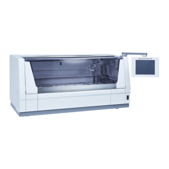
Name of Each Part [10] [11] [1] Cover The cover protects the operator against exposure to dangerous chemicals without obstructing his/her view. [2] Door Open this door when setting or removing tissues. [3] Water supply strainer door Access this area when maintaining the water supply circuit. [4] Power switch [5] Control panel display A touch-panel type display for operating the instrument. - Page 41 Name of Each Part [19] [18] [17] [13] [14] [12] [15] [16] [12] Solution reservoir [13] Wash station Up to 4 wash stations. [14] Drying station [15] Heating station Heating stations permit special stain runs that require heating. [16] Water supply handle Use this handle to adjust the water flow rate.
-
Page 42: Standard Accessories/Options
Standard Accessories/Options [10] [11] [12] [16] [13] [18] [14] [21] [15] [17] [19] [20] [23] [24] [25] [26] [22] [27] [29] [28] [30] [31] [33] [32] [42] [34] [35] [38] [36] [39] [102] [101] [37] [40] [104] [41] [103] 1-22... - Page 43 Standard Accessories/Options No. Product/part name Product code Product code 6170 6171 6172 6173 6174 6175 6177 Q'ty 10-slide basket adapter 6138 K24-418-01 10-slide basket 6137 K24-411-00 20-slide basket adapter 6136 K24-408-01 20-slide basket 4768 K16-500-08 Wash reservoir 6149 K24-403-01 Solution reservoir with handle 6148 K24-400-00 3-position reservoir tray...
-
Page 44: Basics
Basics Basics on This Instrument This section explains the Basics of operating the instrument. For the details of each item, refer to the page indicated in the text. Instrument Overview ● This instrument automatically stains tissues and cell smear samples on glass slides for microscopy, as part of histological studies and tests conducted in the fields of pathology, anatomy, clinical pathology, etc. -
Page 45: Logon/Logoff Function
Basics Logon/Logoff Function The user enters his/her pre-assigned password to log on to the instrument, upon which the instrument becomes operational. Only the user who has logged on can operate the instrument. The operations that are permitted to the logged-on user vary depending on the level of the user’s password. When the user logs off from the instrument during operation, unauthorized instrument operation by a third person can be prevented. -
Page 46: Handling The Touch-Panel Display
Be sure to wait for the confirmation message to appear on the screen before removing the CF card. • Sakura does not warrant the integrity of data stored in CF cards regardless of the failure exhibited by the instrument or monetary damage suffered in connection with the data loss/damage. Sakura does not provide any service associated with the recovery or restoration of data in CF cards. -
Page 47: Various Gateways
Recommended UPS rating: Capable of outputting 15 kVA for 5 minutes Some UPSs are not supported by the instrument. For details, contact the Sakura Finetek Technical Support representative or local representative. The instrument provides an UPS input signal to detect a power outage mode of the UPS connected to the power supply. - Page 48 Specification: 10BASE-T ● 2D bar code reader (optional) By connecting the 2D bar code reader, the instrument can read the bar codes on Sakura staining solutions*. Their expiration dates can be entered in the system based on the bar code information.
-
Page 49: Relationship Of Solution Configurations And Station Numbers
Basics Relationship of Solution Configurations and Station Numbers This section explains the relationship of solution configurations and station numbers shown on the screen. The link station is available only when the instrument is connected to an automated coverslipper. It cannot be used if an automated coverslipper is not connected. - Page 50 Basics ● Arrangement of standard solution stations (with drying stations) In the standard mode, the arrangement and number of stations vary depending on whether the solution stations are arranged "without special solution stations" or "with special solution stations." Station 1 Station 2 Station 3 Station 4...
- Page 51 Basics ● Arrangement of standard solution stations (with drying stations) In the standard mode, the arrangement and number of stations vary depending on whether the solution stations are arranged "without special solution stations" or "with special solution stations." Station 1 Station 2 Station 3 Station 4...
-
Page 52: Explanation Of Menu Screens
Explanation of Menu Screens Stain Process Menu This menu screen appears while the instrument is standing by after logon. This menu screen appears during stain process. 1-32... -
Page 53: Explanation Of Icons In The Stain Process Menu
Touch this icon to check the error history and error descriptions or clear errors. [5] Read Barcode (Optional) Use this setting to read the 2D bar codes on Sakura staining solutions* and enter their expirations in the instrument based on the 2D bar code information. -
Page 54: Utility Menu
Explanation of Menu Screens Utility Menu Explanation of Icons in the Utility Menu [1] System Setup Touch this key to set date/time, set date/time formats, change passwords, set filter use limits, set the institution name, set whether to enable or disable data export, adjust the alarm sound, and set whether or not to output a key input sound. -
Page 55: Edit Menu
Explanation of Menu Screens Edit Menu Explanation of Icons in the Edit Menu [1] Edit Solution Name Select this icon to create a new solution name or edit an existing solution name. (P. 2-23) [2] Edit Solution Configuration Select this icon to create a new solution configuration or edit an existing solution configuration. (P. 2- [3] Edit Program Select this icon to create a new staining program or edit an existing staining program. -
Page 56: System Setup
System Setup System Setup In the System Setup screen accessible from the Utility Menu, you can define the basic settings needed to use the instrument. [10] [11] [12] 1-36... - Page 57 System Setup Date Format This sets the format for the date display. Touching the option button toggles the display format in the sequence of "Year/Month/Day," "Month/Day/Year" and "Day/Month/Year." [2] Time Format This sets the format for the time display. Touching the option button switches the time format between "12 hour format"...
-
Page 58: Setting Date And Time
System Setup Setting Date and Time You can set date and time by touching Date and Time from the System Setup screen accessible from the Utility Menu. Entering Year Touching the Modify button on the right of "Year" displays the numeric keypad. Enter the current year using the numeric keypad. -
Page 59: Setting User Ids, Passwords And Accessible Functions
System Setup Setting User IDs, Passwords and Accessible Functions You can set user IDs and passwords as well as the functions accessible by each user by selecting Password Input from the System Setup screen accessible from the Utility Menu. To set each item, select the applicable user and perform the corresponding operation explained below. -
Page 60: Setting Accessible Functions
System Setup Setting Accessible Functions You can set functions accessible by each user. This operation cannot be performed for "Administrators." Stain Process Staining Mode Selection Touching this function changes permissions for "Staining Mode Selection" between Allowed and Not Allowed. ... -
Page 61: Fume Filter Management
System Setup Fume Filter Management You can set items relating to fume filter management by selecting Fume Filter Management in the System Setup screen accessible from the Utility Menu. Whether or Not to Use Fume Filter Management You can set whether or not to manage the use of fume filters. Touch the button to change between "In Use"... -
Page 62: Adjusting The Water Flow
System Setup Adjusting the Water Flow You can change the run-up time for water supply to the wash stations by selecting Water Flow from the Utility Menu. • Water supply run-up time --- The time at which water supply to the wash stations is started during stain process, prior to the transfer of tissues into the wash stations. -
Page 63: Export Data
Export Data About Exporting Data You can export the following items by selecting Export Data from the Utility Menu. If the output destination is set to "OFF," export operation is disabled. [1] Solution Configuration (Solution Configuration List) Touch this button to export the details of solution configurations created by the user. [2] Stain Program (Stain Program List) Touch this button to export the details of staining programs created by the user. -
Page 64: Names Of Files Exported To A Cf Card
Names of Files Exported to a CF Card If the export destination is set to File, each set of output data is saved to a CF card as a file. The files of each exported item are named in the applicable format shown below. Exported item File name Solution configuration... -
Page 65: Chapter 2 Operating Procedure
Chapter 2 Operating Procedure... -
Page 67: Flow Of Stain Process Operation
Operating Procedure Flow of Stain Process Operation This section explains a series of operating procedures. Flow of Stain Process Operation A basic flow of normal operation is shown below. ● Preparation for Operation Standby Refer to P. 2-2 for details. •... -
Page 68: Preparation For Stain Process
Operating Procedure Preparation for Stain Process Refer to P. 2-12 for details. This section explains the preparation to be performed before the start of stain process. Opening the Water Supply 1. Open the tap water faucet so that water can be supplied. 2. -
Page 69: Selecting And Saving A Solution Configuration And Setting Solutions
Operating Procedure Selecting and Saving a Solution Configuration and Setting Solutions The instrument can store multiple solution configurations and staining programs. Accordingly, you must select a solution configuration appropriate for the staining program you want to run and display the selected configuration on the monitor screen before starting the program. -
Page 70: Setting Slides Into Baskets
Operating Procedure 4. Touching the Select key displays the New Solution Configuration screen. If the new solution configuration you have selected requires changing the arm holder from the 3-position type to 1-position type, or from the 1-position type to 3-position type, the Change Arm Holder window appears with the message asking if the arm holder has been changed. -
Page 71: Start Of Stain Process
Operating Procedure Start of Stain Process This section explains a normal procedure to start stain process. Refer to P. 2-13 for the procedure to start stain process in the "batch mode" by specifying the start step and end step. 1. Touch the Start key at the bottom right of the Stain Process Monitor screen. - Page 72 Operating Procedure 5. Open the door at the bottom of the cover to set a basket into the start station. Push the top of the center of the door toward the back once opens the door toward you. When the door opens, draw out the reservoir in the start station and set by paying attention to the orientation of the basket in which slides have been set.
-
Page 73: Operations Permitted During Stain Process
Operating Procedure Operations Permitted during Stain Process The following operations are permitted during stain process. Addition of baskets and setting of priority start are enabled only in the continuous mode. • Add a basket • Priority start • Check the end station status •... -
Page 74: Setting Priority Start
Operating Procedure 5. Open the door at the bottom of the cover to set a basket into the start station. Confirm that the arm is not on a solution station in the frontmost row. If the arm is in the frontmost row when the door is opened, an error will generate and the operation will pause, which may extend the staining time. -
Page 75: Checking The Staining Status
Operating Procedure Checking the Staining Status You can check the status of the current staining run by touching the Detailed Monitor key in the Stain Process Monitor screen during staining process. The scheduled end time can also be checked in the Detailed Monitor. -
Page 76: Menu Operations Permitted During Staining Process
Operating Procedure Menu Operations Permitted during Staining Process You can perform certain menu operations during stain process by touching the Menu key in the Stain Process Monitor screen. ● Error display Up to 99 errors that have occurred since the start of staining process are displayed, from the latest error shown on top. -
Page 77: Pausing And Aborting Stain Process
Operating Procedure Pausing and Aborting Stain Process This section explains the procedures to pause and abort stain process. The abort operation can be performed only after the pause operation. ● Pause operation To pause staining process, touch the Pause key on the left of the Stain Process Monitor screen. Touching the Pause key displays the pausing window. -
Page 78: Removing A Basket During Stain Process
Operating Procedure Removing a Basket during Stain Process The following operation is performed when removing a basket from the end station or PE station during stain process or after completion of stain process. It cannot be performed if the end station or PE station contains no basket. -
Page 79: How To Start Stain Process By Specifying The Start And End Steps
Operating Procedure How to Start Stain Process by Specifying the Start and End Steps You can start stain process by specifying the start and end steps only in the batch mode. If a desired step is specified as the start step, the staining program will start from the specified step. If a desired step is specified as the end step, staining process will end at the specified step and the baskets will be transferred to the end station specified in the applicable staining program. - Page 80 Operating Procedure 1. Touch the Start key at the bottom right of the Stain Process Monitor screen. If the Stain Process Monitor screen is not currently displayed, complete or abort the current operation and touch the Exit key or Reset key at the bottom right of the screen to return to the Stain Process Monitor screen. 2.
-
Page 81: Setting A Solution Configuration
Setting a Solution Configuration From "Solution Configuration," you can set a configuration of necessary solution stations and other items that are needed to run the staining program smoothly. Creating a New Solution Configuration This section explains the procedure to create a new solution configuration. Up to 50 solution configurations can be saved. -
Page 82: Setting Up A Solution Configuration
Setting a Solution Configuration Setting Up a Solution Configuration Setting a solution configuration name displays the Solution Configuration Setup window. In this screen, the entire solution configuration can be set. The setting of each item is explained below. ● Solution Configuration Type You can select whether to use standard solution reservoirs (Standard) or small solution reservoirs (Small). -
Page 83: Setting An Edit Solution Configuration
Setting a Solution Configuration ● Number of Wash Stations Determine how many wash stations to be used or no wash station will be used. If used, up to four wash stations can be set. Touching this button toggles in the sequence of Not In Use, 1 Station, 2 Stations, 3 Stations and 4 Stations. - Page 84 1. In the Edit Solution Configuration screen, touch the station you want to set a solution for. Select a desired solution name from "Standard Solutions," "Sakura Solutions * " and "Kit Solutions * " in the solution setting field.
- Page 85 Setting a Solution Configuration ● How to Set Station and Group Colors Touching Properties in the Edit Solution Configuration screen opens another screen where you can set display colors for the selected solution configuration as well as items relating to staining control.
-
Page 86: Mix Parameter Setup
Setting a Solution Configuration ● How to Set Staining Control Data At staining control data, you can set detailed staining controls by touching Mix, Enhanced Wash, Basket Lifting Speed, Water Wash Cycle Time and Temperature Settings. These items can be set separately for each solution configuration. -
Page 87: Basket Lifting Speed And Water Wash Cycle Time Parameter Setup
Setting a Solution Configuration Basket Lifting Speed and Water Wash Cycle Time Parameter Setup • Basket Lifting Speed You can set the speed at which baskets are lifted. Select a desired slider and move it to right or left to change the setting. -
Page 88: Editing A Solution Configuration
Setting a Solution Configuration Editing a Solution Configuration This section explains the procedure to edit an existing solution configuration. 1. Touch Menu at the bottom right of the Stain Process Monitor screen. 2. Select Edit Solution Configuration in the Edit Menu. 3. -
Page 89: Editing A Solution Name
Setting a Solution Configuration Editing a Solution Name This section explains the procedure to set a solution name. Up to 100 solution names can be saved. Each solution name must consist of up to 20 alphanumeric characters. Creating and Editing a Solution Name 1. -
Page 90: Copying A Solution Name
Setting a Solution Configuration Copying a Solution Name 1. Touch Menu at the bottom right of the Stain Process Monitor screen. 2. Select Edit Solution Name from the Edit Menu. 3. Under Solution List in the Edit Solution Name screen, touch and select the solution you want to copy and then touch the Copy key. -
Page 91: Setting A Staining Program
Setting a Staining Program "Staining programs" are programs that automatically perform stain process based on preset "solution configurations." Refer to P. 2-15 for "solution configurations." Creating a New Staining Program This section explains the procedure to create a new staining program from a preset "solution configuration."... -
Page 92: Creating A Staining Program
Setting a Staining Program Creating a Staining Program To create a staining program, touch a desired item or select a desired location using the cursor keys located at the bottom right. The procedure to create each item is explained below. ●... - Page 93 Setting a Staining Program ● How to operate the "Station" field "Station" refers to each station number assigned to the currently selected solution configuration. You can touch and select each "Station" field in the Edit Program screen and then select Select Station or Program End Station to perform the applicable operation.
- Page 94 Setting a Staining Program ● How to operate the "Time" field In the "Time" field, you can set a processing time for the currently selected solution. Set a desired time in the "Hours: Minutes: Seconds" format. The maximum time that can be entered is "99:59:59." •...
- Page 95 Setting a Staining Program ● How to operate the "Delay" field "Delay" refers to an "allowable delay" to be applied to a staining run in order to run another staining run when multiple staining runs must be performed at the same time in the continuous mode while delaying other stain process.
- Page 96 Setting a Staining Program ● How to operate the "Mix" field In the "Mix" field, you can set whether to perform "mixing" and "enhanced wash" during staining. Use of these operations that closely simulate manual staining prevents mottled colors and co-staining to enhance the staining quality.
-
Page 97: Editing A Staining Program
Setting a Staining Program Editing a Staining Program This section explains the procedure to edit an existing staining program. 1. Touch Menu at the bottom right of the Stain Process Monitor screen. 2. Select Edit Program from the Edit Menu. 3. -
Page 98: Copying A Staining Program
Setting a Staining Program Copying a Staining Program This section explains the procedure to copy a staining program. 1. Touch Menu at the bottom right of the Stain Process Monitor screen. 2. Select Edit Program from the Edit Menu. 3. Under Program List in the Select Program screen, touch and select the name of the staining program you want to copy, and then touch the Copy key. -
Page 99: Checking A Staining Program
Setting a Staining Program Checking a Staining Program This section explains the procedure to check if a given combination of solution configuration and staining program is feasible. 1. Touch Menu at the bottom right of the Stain Process Monitor screen. 2. -
Page 100: How To Use The Bar Code Reader, And It's Function (Options)
Applicable Solutions - Sakura staining solutions* - Staining kits* * Check the local Sakura Finetek website for availability of the Sakura staining solutions and staining kits. How to Use Sakura Staining Solutions Editing a Solution Configuration 1. When a special solution is used, select Edit Solution Configuration [1] on the Edit Menu, to move to the Solution Configuration Setup screen. -
Page 101: How To Enter Sakura Solution Bar Code Data
How to Use the Bar Code Reader, and It's Function (Options) How to Enter Sakura Solution Bar Code Data 1. Prepare the solution to be set to the instrument. 2. Touch the Read Barcode button on the Stain Process Menu. -
Page 102: How To Use Sakura Staining Kit
Sakura staining solutions managed by bar code Sakura solutions * "*" is attached at the beginning of the solution name. Solutions that constitute the Sakura staining kits managed by bar code Kit solutions * "/" is attached at the beginning of the solution name. -
Page 103: How To Enter Kit Component Solution Bar Code Data
Only the stations for which bar code can be entered are displayed. The bar code reading procedure and solution state vary depending on the station/text color, so use the table below as reference. Station color Sakura staining Yellow solution station Kit staining solution... - Page 104 How to Use the Bar Code Reader, and It's Function (Options) 7. Once the bar code of the solution has been read, the information of the solution is displayed on the screen, as with the kit. 8. If the information displayed on the screen is correct, set the station containing the special solution as the specified station in the instrument.
-
Page 105: Resetting The Solution Usage Information
How to Use the Bar Code Reader, and It's Function (Options) Resetting the Solution Usage Information You can select the Reset Solution Usage Information screen from the Stain Process Menu and check for expired solutions and reset their usage information. You can also move to the Read Bar Code screen from the Reset Solution Usage Information screen. -
Page 106: Outputting Process Report
25(H2) 26(E1-1) End Station1 27(E1-2) End Station1 28(E1-3) End Station1 29(S3) Start Station 30(S2) Start Station 31(S1) Start Station ----------------------- Sakura solution information---------------------- Station Lot Number Exp.(Unopened) Exp. Time Date Opened Exp.(Use) 123456 2017-12-13 2017-03-08 2017-03-21 123456 2017-12-13 2017-03-08 2017-03-21... -
Page 107: Process Report
Alcohol 100% 00:01:00 00:01:00 Xylene 00:01:00 00:01:00 Xylene 00:01:00 00:01:00 Xylene 00:01:00 00:01:00 E1-* End Station 1 --:--:-- 00:58:53 -------------------------- Sakura solution information ---------------------- Station Lot Number Exp.(Unopened) Exp. Time Date Opened Exp.(Use) 123456 2017-12-13 2017-03-08 2017-03-21 123456 2017-12-25 2017-01-05 2017-01-18... -
Page 108: Solution Configuration Report
How to Use the Bar Code Reader, and It's Function (Options) Solution Configuration Report You can output this report by touching Solution Configuration List on the Export Data screen. The solution configuration report also shows the staining kit name. [Example] Configuration --------------------- Solution... -
Page 109: Barcode History Report
How to Use the Bar Code Reader, and It's Function (Options) Barcode History Report You can output this report by touching Barcode History on the Export Data screen. The barcode history shows the GTIN of each barcode that has been read, lot number, and the date the barcode was read, for up to 1,000 most recently read barcodes. -
Page 110: Deleting A Solution Configuration/Staining Program/Solution Name/Process Report
Deleting Data Deleting a Solution Configuration/Staining Program/Solution Name/Process Report This section explains the procedure to delete each item (solution configuration/staining program/solution name/process report). Deleting a Solution Configuration 1. Touch Menu at the bottom right of the Stain Process Monitor screen, and then select Delete Data in the Edit Menu. -
Page 111: Deleting A Staining Program
Deleting Data Deleting a Staining Program 1. Touch Menu at the bottom right of the Stain Process Monitor screen, and then select Delete Data in the Edit Menu. 2. When the Delete Data screen appears, select Program. 3. Touching the key displays the Deletion Procedure window. -
Page 112: Action To Be Taken Upon Power Outage
Action to Be Taken upon Power Outage Power Recovery Operation This section explains the operation to be performed if a power outage occurred during the stain process. Once the power is restored, perform the power recovery operation explained below. 1. Once the power is restored, an error buzzer sounds and the Power Outage Alarm screen or Arm Error window appears on the control panel display to inform the operator that a power outage has occurred. -
Page 113: Action To Be Taken Upon Error
In the event of an unexpected problem for which you cannot find any solution, immediately turn off the power. Next, open the cover, remove the tissues, and protect them so as not to let them dry up. Then, contact the Sakura Finetek Technical Support representative or local representative. -
Page 114: Chapter 3 Maintenance And Inspection
Chapter 3 Maintenance and Inspection... -
Page 115: Daily Inspection And Cleaning
Daily Inspection and Cleaning Inspection and Cleaning Methods Inspect and clean the instrument periodically to prevent instrument malfunction and failure. Unless otherwise specified in this manual, perform inspection and cleaning with the power turned off. Cleaning the Solution Reservoirs and Baskets Clean solution reservoirs and baskets with water or neutral detergent. -
Page 116: Replacing Activated Carbon Filters
Daily Inspection and Cleaning Replacing Activated Carbon Filters When to replace the activated carbon filters can be easily determined by setting a time limit using the fume filter management function (refer to P. 1-41 for details). Always replace the two activated carbon filters in each filter pair together. -
Page 117: Cleaning The Water Supply Strainer
Oxidizing chlorides [ferric chloride (FeCl3), sodium tiosulfate (Na22O3), organic acid (HCOOH), acetic acid (CH3COOH), bromic acid (C204H2), lactic acid (CH3CH(OH)COOH), etc.)] If this is not performed, the metal parts may corrode (rust, etc.) quickly. Contact the Sakura Finetek Technical Support representative or local representative for use of metal cleaners. -
Page 118: Cleaning The Wash Station Nozzle
Refer to P. 1-10 for the installation method of the drain hose. If you have any question regarding cleaning, contact the Sakura Finetek Technical Support representative or local representative. -
Page 119: Chapter 4 Troubleshooting
Chapter 4 Troubleshooting... -
Page 121: Error Codes Displayed During System Operation
If the problem persists after taking the specified action, or if the specific problem you have encountered is not listed in the chart, contact the Sakura Finetek Technical Support representative or local representative. The number in the table indicates the corresponding error number. - Page 122 An incompletely latched door suddenly opened during Contact the Sakura Finetek the staining process. Technical Support representative or local representative. The instrument malfunctioned during the staining process due to a door open/close sensor error.
- Page 123 Name Cause Action number Deviation Error Movement of the Y-axis is inhibited by an obstacle or faulty Contact the Sakura Finetek (Y axis) wire drive. Technical Support representative or local representative. The Y-axis home sensor is faulty. The Y-axis encoder is faulty.
- Page 124 Error Name Cause Action number Fan Stop The fan is faulty. Contact the Sakura (Drying Station 1) Finetek Technical An operation signal was not output due to a controller board Support representative or error. local representative. The connection cable connecting the temperature controller board and the controller board was disconnected.
- Page 125 Cause Action number Sensor Opened An abnormal value was input to the signal amplification part of the Contact the Sakura Finetek (Heating Station 2) Technical Support controller board due to a disconnected temperature sensor. representative or local The heating station connection harness connecting the temperature representative.
- Page 126 Name Cause Action number Thermal Fuse The SSR3 on the temperature controller board experienced a Contact the Sakura (Heating Station 2) short-circuit failure. Finetek Technical Support representative or The heater remained on due to a driver error of the controller local representative.
-
Page 127: Instrument Conditions And Recovery Actions
Use this information to identify the instrument condition and resolve the problem. If the problem persists after taking the specified action, or if the specific problem you have encountered is not listed in the chart, contact the Sakura Finetek Technical Support representative or local representative. - Page 128 Troubleshooting...
- Page 129 Condition Check Action A special staining tray can The detection pin no longer moves. Contact the Sakura Finetek Technical Support no longer be recognized. representative or local representative. False detection occurred due to a special staining tray detection sensor error.
- Page 130 The basket adapter has deformed. Contact the Sakura Finetek Technical Support representative or local representative. The home detection mechanism of each axis has not been adjusted correctly. When the facility is The water supply plug on the facility side, or the flow rate Open the flow rate adjustment valve.
- Page 131 Dirty or solution is attached. Clean the cover if dirty or solution is deteriorated. attached. Effect of ultraviolet light. Contact the Sakura Finetek Technical Support representative or local representative. The temperature at the installation location has changed. Use the instrument in an environment free from temperature difference.
- Page 132 Troubleshooting Please visit our website sakura.eu Sakura Finetek Europe B.V., Flemingweg 10a, 2408 AV Alphen aan den Rijn, P.O. Box 362, 2400 AJ Alphen aan den Rijn, The Netherlands Sakura Finetek Japan Co., Ltd. 1-9 Honcho 3-chome Nihombashi Chuo-ku Tokyo, Japan...
Need help?
Do you have a question about the Tissue-Tek Prisma Plus and is the answer not in the manual?
Questions and answers
Do this machine need calibration? if so how is it done. How are you running controls on this machine?