Subscribe to Our Youtube Channel
Summary of Contents for Rosco SAFE -T-SCOPE
- Page 1 STSK7360 SAFE -T-SCOPE ® R E A R V I E W B A C K U P C A M E R A S Y S T E M S STSK7360 INSTALLATION / USER'S MANUAL...
-
Page 2: Table Of Contents
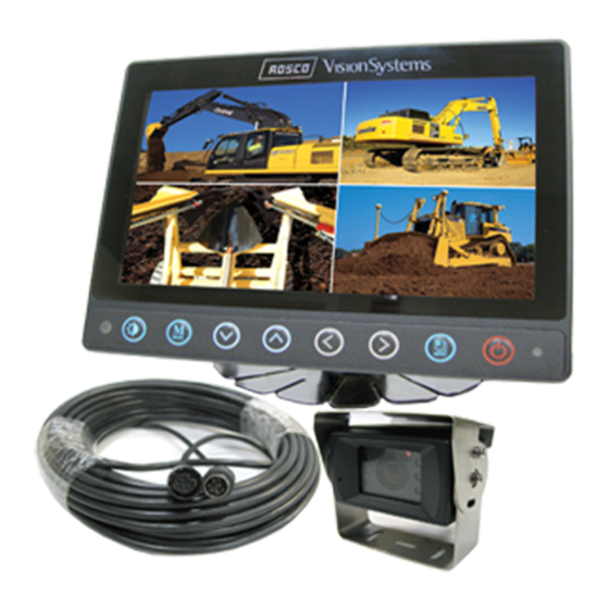
® This information is for preventing damage. This information is for preventing bodily harm. User should follow safety rules. Rosco Vision Systems introduces a revolutionary new backup camera system for commercial vehicles. The STSK7360 Safe-T-Scope backup camera system utilizes ®... -
Page 3: Safeguard Instructions
• Before using this product, please check contents below. If there are - THIS MAY CAUSE ELECTRONIC SHOCK OR MALFUNCTION. any missing parts please contact a Rosco sales agent or dealer. • Please use this product within the voltage range specified - THIS MAY CAUSE ELECTRONIC SHOCK OR MALFUNCTION. -
Page 4: Installation Instructions
Safe-T-Scope STSK7360 ® Backup Camera System INSTALLATION INSTRUCTIONS FEATURES AND CONTENTS IMPORTANT: FOR TYPICAL REAR-VIEW INSTALLATION, THE REAR CAMERA MUST BE CONNECTED TO THE MONITOR POWER DISTRIBUTION HARNESS AT THE CONNECTOR MARKED “REVERSE” Note: The following instructions are for a typical rear-view application. STSC107 CAMERA 1. -
Page 5: Wiring Camera & Monitor
Safe-T-Scope STSK7360 ® Backup Camera System WIRING CAMERA AND MONITOR MONITOR FUNCTIONS AND OPERATIONS MONITOR 1. Connect the red wire to an ignition switched accessory (ex: radio) power source, 1. POWER and connect the black wire to chassis ground. See wiring diagram for connections When the ignition is switched on, the monitor will be in standby mode (no image (See Fig. -
Page 6: Functions & Operations
Safe-T-Scope STSK7360 ® Backup Camera System FUNCTIONS AND OPERATIONS FUNCTIONS AND OPERATIONS 2. CAMERA SELECTION From the FULL SCREEN in the full screen, press the button to see 4. CAMERA SELECTION FOR 3 SPLIT SCREENS CAM1 > CAM2 > CAM3 > CAM4 > CAM1 ..In the 3 split screen press the “Mode“... - Page 7 Safe-T-Scope STSK7360 ® Backup Camera System FUNCTIONS AND OPERATIONS FUNCTIONS AND OPERATIONS IMPORTANT CAM2 OR CAM3 FULL SCREEN From the CAM2 or CAM3 full screen press the “Mode” button. From the • The on screen distance markers should be considered as a general reference to assist the driver in assessing the distances depicted on the screen.
- Page 8 Safe-T-Scope STSK7360 ® Backup Camera System FUNCTIONS AND OPERATIONS FUNCTIONS AND OPERATIONS 2. If there is trigger input, the connected screen (Trigger input screen) is displayed as MARKER ADJUSTMENT (ADJUSTING THE BUMPER POSITION) full screen and the screen goes former one when the signal disappear. - Press “Mode“...
-
Page 9: Setting
Safe-T-Scope STSK7360 ® Backup Camera System FUNCTIONS AND OPERATIONS FUNCTIONS AND OPERATIONS 5. When there is the TRG1(Rear light) input, CAM1 video will be shown on the screen. with button, the 2 split screen CAM2/CAM1 or CAM1/CAM3 could be displayed. 7. - Page 10 Safe-T-Scope STSK7360 ® Backup Camera System DIMMER SETTINGS 2. Dimmer sensor setting Press the “MODE“ button until OSD menu “PICTURE SETUP“ appears. Press button to select “DIMMER“ and use to enter selection. FACTORY SETTINGS Press the “DAY/NIGHT“ button to switch DAY >> NIGHT >> AUTO >> DAY 5.
-
Page 11: Connection
Safe-T-Scope STSK7360 ® Backup Camera System INSTALLATION OF DUCKMOUNT CONNECTION 1. Ensure that the monitor is installed with enough room for heat emission. Install the MINI-DIN A TYPE monitor stand with enclosed screws and double side adhesive tape as shown in the above image. - Page 12 Safe-T-Scope STSK7360 ® Backup Camera System FIG. 1 FIG. 2 Position of camera Camera mount in suggested location Mount Camera assembly high. (centered) Vehicles behind truck Street Camera Mounting Hole Pattern Rear Bumper Typical monitor image of view from properly installed camera...
- Page 13 Safe-T-Scope STSK7360 ® Backup Camera System FIG. 3 FIG. 4 Optional Wind Deflector Mounting on ceiling Mounting on the dash, console etc.
- Page 14 Safe-T-Scope STSK7360 ® Backup Camera System FIG. 5 STSC107 STSM207 15 PIN DIN (M-F) CONN (F-M) NOTES STSH307 (65FT’) STSH347 (32 inches) (M-F) Cam 1 Trigger Cam 2 Trigger Cam 3 Trigger Cam 4 Trigger Positive 12VDC * Black wire is the reverse trigger wire, connect to vehicle backup light circuit.
- Page 15 A CENTURY OF AUTOMOTIVE VISION SAFETY 90-21 144th Place, Jamaica, New York 11435 TEL (800) 227-2095 • FAX (718) 297-0323 info@roscomirrors.com www.roscomirrors.com www.roscovision.com M080116B...


Need help?
Do you have a question about the SAFE -T-SCOPE and is the answer not in the manual?
Questions and answers