Table of Contents
Advertisement
Quick Links
Advertisement
Table of Contents

Subscribe to Our Youtube Channel
Related Manuals for Bosch EPS 610


Summary of Contents for Bosch EPS 610
- Page 1 EPS 610 en Original instructions Injection pump test bench...
-
Page 3: Table Of Contents
Cleaning the suction strainer Transportation 8.3.7 Flexible coupling Unpacking the EPS 610 8.3.8 Adjusting the MGT tray Moving the EPS 610 to the installation location Decommissioning Before turning on for the first time Temporary shutdown 4.4.1 Installation Change of location 4.4.2... -
Page 4: Symbols Used
¶ sequences of the hazard as well as preventive action. Never hold your hand anywhere near the Warning notices have the following structure: flywheel when the EPS 610 is in opera- tion! Warning ¶ KEY WORD – Nature and source of hazard! Cover rotating parts. -
Page 5: User Information
Dispose of used electrical and electronic devic- es, including cables, accessories and batteries, connection and operation of the EPS 610 and must al- separately from household waste. ways be heeded. Bosch Limited... -
Page 6: Product Description
Flexible coupling (mounted on bench) heavy-duty fuel injection pump calibration test bench. Coupling guard (mounted on bench) The EPS 610 can be used for checking Bosch distribu- Measuring glass - 30 cc (8 nos.) tor/in-line injection pumps PE(S) A, M, MW, P 3000 to Measuring glass - 180 cc (8 nos.) -
Page 7: Description Of Unit
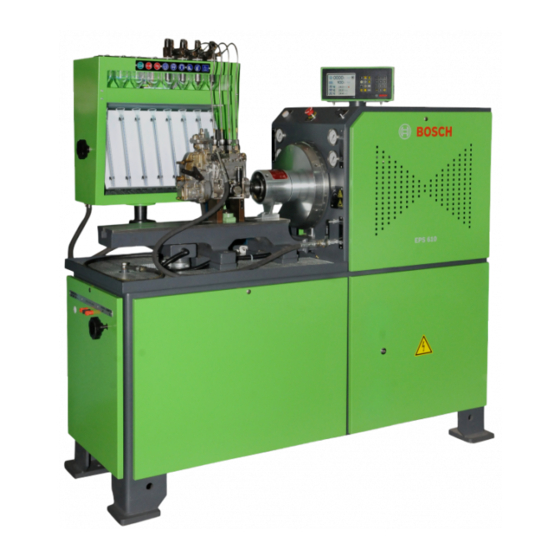
Product description | EPS 610 | 7 Description of unit 3.5.1 EPS 610 Fig. 1: EPS 610 1 Measuring glass carrier (MGT) assembly 2 "Mains on" indicator 3 Emergency stop 4 Human Machine Interface (HMI) 5 MGT illumination switch 6 Motor Right Hand (RH) side panel... -
Page 8: Drive
5 Low inlet pressure gauge, -100 – 300 kPa The ISO drive coupling is a safety compo- 6 High pressure gauge, 0 – 6 MPa nent of the EPS 610. The ISO drive coupling may only be repaired only by Bosch service 3.5.4 Frame technicians. - Page 9 Product description | EPS 610 | 9 Fig. 4: Movement of the swivel plate 1 Knob 2 Cam plate Fig. 5: MGT height adjustment mechanism 3 Hose 1 Bush 2 Locking screw for MGT vertical movement 3 Screws for fixing the vertical guide...
-
Page 10: Control Cabinet
The HMI can be turned and positioned conveniently for ¶ Do not touch the frequency drive or the viewing the display from either side of the EPS 610 (re- braking resistor for 10 minutes after fer Fig. 21). switching off the mains supply. -
Page 11: Test Oil Supply Unit
Product description | EPS 610 | 11 Test oil tank 3.5.8 Test oil supply unit The test oil tank, mounted on the frame of the EPS 610, has a capacity of 50 lts. To access the test oil tank, open the rear bottom panel. -
Page 12: Heating The Test Oil
70°C, the EPS 610 initiates emergency automatically. The EPS 610 can be restarted and the test oil heating can be switched on again after the temperature of the test oil reduces below 70°C. -
Page 13: Initial Start-Up
They have to be preserved for inspection by Bosch and the insurance company. The base of the EPS 610 is mounted and bolted to a wooden pallet. It is also covered with polythene and Observe the method of packaging on one side. -
Page 14: Before Turning On For The First Time
2. Place a spirit level on the test pump mounting bed (Fig. 1, Pos. 10). 3. Check if the EPS 610 is placed on a flat surface. Else, lift the bench and place shims beneath the dampers till the flatness is OK. -
Page 15: Mains Connections
¶ Cover or cordon off live parts. The EPS 610 must be connected to the mains (400 V - 440 V). It is recommended to use a current- limiting circuit-breaker with a rating of 300 mA. -
Page 16: Test Oil Connections
The HMI connection is complete. 4.4.4 Test oil connections All the test oil connections of the EPS 610 are con- nected at the factory and are ready to use. 1. Open the bottom right panel (Fig. 1, Pos. 11). 2. Check if any hydraulic connections are disconnected. -
Page 17: Connection For Cooling Water
3. Ensure that the connections are leak-proof. The cooling water supply valve to the bench must be Heater on / off Switch on/ off the heater closed when EPS 610 is not in use. Temperature selec- Change the set temper- 4.4.6... -
Page 18: Operation Of The Hmi
Operation of the HMI left: actual temperature right: target temperature As a good practice, it is recommended to switch on Inlet temperature and switch off the EPS 610 twice before first opera- left: actual temperature right: target temperature tion. Outlet temperature left: actual temperature ¶... -
Page 19: Change Direction Of Rotation
Program description | EPS 610 | 19 Automatic selection of stroke count 5.3.2 Change direction of rotation and motor speed Do not attempt to change the direction of rotation The automode feature provides easy selection of preset when the motor is in operation. -
Page 20: Saving Customer-Specific Speed Rates
Switch-on 1. Close the shut-off cock for the test oil supply. 2. Switch on the EPS 610 at the master switch. The EPS 610 is ready for operation. 3. Press the <Heater on /off> key to start heating the test oil. -
Page 21: Switch-Off
" The EPS 610 is switched off. pump. There is a delay of 15 seconds for the EPS 610 to 1. Using the required mounting accessories, mount the start when it is switched off successively. injection pump to be tested on the pump mounting bed. -
Page 22: Checking Pre-Stroke, Start Of Delivery And Cam Offset For In-Line Pumps
22 | EPS 610 | Operation The temperature sensor on the flushing valve must 8. Continue rotating the flywheel in the direction of the always be fitted in such a way that the connecting injection pump. The cam on the fuel injection pump camshaft cable in a vertical position. -
Page 23: Checking Start Of Delivery For Distributor Pumps With Pre-Stroke Specifications
Operation | EPS 610 | 23 Troubleshooting Checking start of delivery for distrib- utor pumps with pre-stroke specifica- tions If some of the actions recommended in this chapter cannot be performed, contact customer service. The Voltage is supplied to the solenoid valve of the injec- error messages listed in this chapter are displayed tion pump via the connection cables. -
Page 24: System Error Messages
R Emergency cable damaged. Error code 02 is displayed continuously for 30 seconds till the EPS 610 can be started again. R The test oil level is less than the predefined value. R Check the quantity of oil available in the tank. At least R Oil level sensor cable damaged. -
Page 25: Drive Error Messages
R Check the parameter setting, it should be as per the 1004 DC overvoltage electrical circuit diagram. R Switch off the EPS 610 and switch on. R If the error persists, contact customer service to re- place the frequency drive. R Check the condition of the fuel injection pump under... -
Page 26: Maintenance
The maintenance intervals are recommended be performed by persons with sufficient knowledge under the assumption that the EPS 610 is operated for and experience of electrical and hydraulic systems. 8 hours at a vehicle service center. The intervals have to be reduced if the operating time is extended. -
Page 27: Removing Contaminated Test Oil
Maintenance | EPS 610 | 27 8.3.2 Removing contaminated test oil 8.3.3 Cleaning the MGT strainer The strainer is located beneath the perforated base The contaminated oil must be drained weekly, or as plate. The test oil from the MGT is routed back to the required. -
Page 28: Draining The Test Oil From The Test Oil Tank
28 | EPS 610 | Maintenance 1. Switch off the mains supply. 10. Reach beneath the base of the EPS 610 and open 2. Open the bottom right panel. the drain. The remaining test oil starts collecting in the 3. -
Page 29: Flexible Coupling
18. Connect the power cable to the mains supply. 19. Switch on the mains supply. 20. Switch on the master switch of the EPS 610. 21. Press the <Control on> key and start the test oil motor. Check for any leakage. -
Page 30: Decommissioning
¶ The EPS 610 is only ever to be transported in the used oils of a different category, gasoline or diesel. original or equivalent packaging. The corresponding refuse code number can be taken ¶... -
Page 31: 10. Technical Data
Technical data | EPS 610 | 31 10. Technical data 10.1 EPS 610 Property Unit Value Overall dimensions Length 1770 Height 1720 Width Weight Drive motor Voltage 400 - 415 Frequency Ingress protection IP32 (Overall bench including HMI) IP43 (Elactrical cabinet) -
Page 32: Bench Layout
32 | EPS 610 | Technical data Property Unit Value Angular rotation of the display unit degrees 45 (on each side) Noise Workplace emission sound pressure level L with drive motor dB-A 83.18 running at a speed of 4000 min-1 and without injection pump... -
Page 33: Tightening Torques
Technical data | EPS 610 | 33 10.3 Tightening torques 10.4 Machinery noise information pursuant to the bench safety code For the purpose of safety, the tightening torques listed in the following sections must be used during routine Noise measurement performed in accordance with maintenance or during repair. - Page 36 Bosch Limited P.B. No.3000, Hosur Road, Bangalore 560 030 INDIA www.boschindia.com Mailbox.service2@in.bosch.com F 002 DG9 918 | 2017-10-16...
Need help?
Do you have a question about the EPS 610 and is the answer not in the manual?
Questions and answers